
3
Overview of the Technology
DEVICE PHYSICS
Thermionic energy conversion is a process that converts heat directly into electrical power. In its most elementary form, a thermionic converter consists of two metal electrodes separated by a narrow gap (see Figures 3.1 and 3.2). One of the electrodes, called the emitter, is held at a high temperature, typically 1800 to 2000 K. The other electrode, called the collector, is held at a lower temperature, typically 900 to 1000 K. The emitter emits electrons into the gap and the lower temperature collector absorbs them. The binding energies of
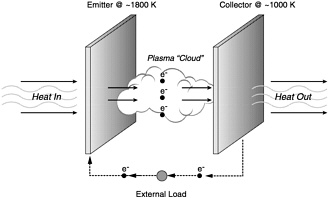
FIGURE 3.1 Basic thermionic converter schematic.
SOURCE: L.Begg, General Atomics, presentation to the Committee on Thermionic Research and Technology, August 2000.
the emitter and collector surfaces that act on electrons are known as the work functions of the electrode surfaces. The electrons absorbed by the collector produce a usable electrical current as they return to the emitter through an external circuit. Electrical power is produced by virtue of the potential difference between the emitter and collector.
A thermionic converter is a static device that has no moving mechanical parts. The device operates at high temperatures, generates high power, and occupies only a small volume. For these reasons, thermionic converters have been considered potentially useful as power
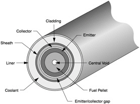
FIGURE 3.2 A cross sectional view of a thermionic fuel element (TFE). The nuclear fuel is located in the middle of the TFE and radiates heat outward.
SOURCE: Oregon State University, Nuclear Engineering and Radiation Health Physics, Department of Nuclear Engineering.
sources for use in space as well as for high temperature terrestrial power systems that generate large amounts of excess heat, such as coal or natural gas fired power plants. The United States, France, Germany, Sweden, Holland, and Russia have pursued thermionic research and development since the early 1960s. More recently China has begun investigating thermionic conversion technologies. Research is still ongoing in Russia, Sweden, and China. The committee does not know the current status of thermionics research in France, Germany, or Holland.
Efficient operation of a thermionic converter requires an emitter surface with a relatively low work function of 3 electron volts or less and an even lower collector work function of 1.5 electron volts or less.1 The converter must also have the right charge transport conditions in the interelectrode gap, the area between the emitter and collector surfaces, to allow electrons to flow from the emitter to the collector.
Historically, emitters with low work functions were made for vacuum tubes by coating a metallic surface with compounds such as barium-calcium-strontium oxide. Such a technique proved to be impractical for thermionic converters because these compounds evaporated, limiting converter life to a few hundred hours.
Another problem relating to the operation of a practical thermionic converter is that the emitted electrons passing through the interelectrode gap create a negative voltage barrier in the gap. When electrons leave the emitter surface, they sense the negative space charge in the interelectrode gap and are forced to return to the emitter surface. In this way, the flow of current is obstructed. The negative space charge of the electron gas in the interelectrode gap must be suppressed to allow sufficient current to flow.
One solution to the negative space charge problem is to make the interelectrode gap small enough to be less than the mean free path of the emitted electrons. One type of thermionic device, the vacuum converter, obtains practical output currents by reducing the interelectrode spacing to a few micrometers (~5). The gap is small enough so that the electrons do not have the opportunity to collide with one another or to accumulate in the gap where they can create a space charge. The electrons are absorbed by the collector before this can happen.
The principal technical challenge in making such devices is maintaining the extremely close spacing required. A mechanically stable electrode support structure also conducts too much heat from the emitter.
Vacuum converters, while possible to construct, have proven to be impractical as power producing devices.
Typical thermionic converters have a significantly larger separation between the emitter and collector, but use cesium in the gap to nullify the negative space charge effect. Figure 3.3 illustrates the change in output voltage as a function of the distance between the emitter and collector in a cesium environment. The graph presents data generated by the Jet Propulsion Laboratory (JPL) Solar Energy Technology (SET) program team in approximately 1967. The data are for an ignited mode converter, and the peak performance is at the optimum spacing of approximately 3.5 mils (88.9 micrometers). The voltage output is lower on the right side of the graph as a result of an increasing negative space charge. The smaller spacing between the emitter and collector, as represented on the left side of the graph, results in a lower voltage output. The linear output at very low spacing, also at the left, is equivalent to the performance of a close-spaced vacuum thermionic converter.
The solution to the negative space charge problem and device spacing problems is provided by the introduction of cesium vapor into the interelectrode gap. Cesium vapor accomplishes two things. First, a layer of adsorbed cesium is formed on both the emitter and collector surfaces that reduces the surfaces’ work functions and improves converter efficiency. Second, the cesium vapor is ionized and forms a plasma in the interelectrode gap. The positive ions neutralize the negative space charge of the electron gas.
There are several operational modes of the cesium plasma, two of which are considered to be important. In the unignited mode, also called the “Knudsen mode” when operating at low pressures and the “diffusion mode” when operating at higher pressures, the plasma is maintained by thermal ionization of cesium vapor contacting the hot emitter surface. This method requires no internal electrical power losses for plasma production. The unignited mode requires a very high emitter temperature, typically greater than 2200 K, as well as a low cesium pressure, typically 0.1 torr. The system has an interelectrode gap separation of approximately 0.2 millimeters.
The ignited mode, also called the arc mode, is a mode in which the plasma is maintained by impact ionization of interelectrode cesium vapor atoms by a highly energetic and very hot electron gas. The electron gas is heated by ohmic electrical power dissipation in the plasma to a temperature of greater than 3200
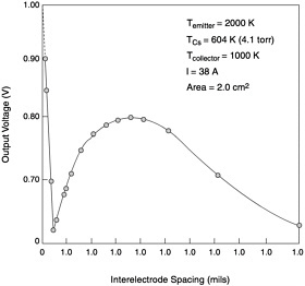
FIGURE 3.3 Solar thermionic output voltage based on emitter-collector spacing.
SOURCE: Jet Propulsion Laboratory, Solar Energy Technology program unpublished data, circa 1967.
K in this non-equilibrium process. This mode requires an emitter temperature of between 1600 and 2000 K and a relatively high cesium pressure of 1 torr. The interelectrode gap for this mode also has a moderate spacing, approximately 0.3 millimeters. The arc potential drop required to maintain the hot plasma is minimized at approximately 0.5 volts. This is the drop in voltage of the device resulting from maintaining the high temperature of the plasma. To date, only the ignited mode of operation has been used for practical applications. Figure 3.4 illustrates the voltage and current density characteristics for the various converter configurations.
The high temperature of the emitter can be maintained by any high temperature heat source. For terrestrial applications, thermionic converters may potentially be used with coal or gas fired electrical plants, as discussed in Chapter 6. For space missions, two heat sources could power thermionic converters: solar and nuclear.
A solar thermionic system, as described in Chapter 4, would consist of a solar concentrator that heats the emitter using the Sun’s energy. A nuclear system can use thermionic converters located either inside the nuclear core, called “in-core systems,” or outside the nuclear core, called “out-of-core systems.” Both nuclear in-core and out-of-core systems consist of a reactor, which generates heat; a thermionic converter, which uses the heat to produce electrical power; and a radiator, which rejects waste heat. However, the out-of-core system also requires a core-to-converter heat transport mechanism, such as a heat pipe assembly or pumped liquid metal recirculating system, to deliver the thermal energy to the thermionic converter since the converters are not in direct contact with the heat in the reactor core.
In-core thermionic converters use thermionic fuel elements that contain both the thermionic converter (or converters) and the nuclear fuel. The most common design consists of a fuel rod that is placed inside a hollow cylindrical thermionic fuel element. The heat is transferred to the emitter on the inside of the hollow cylinder, and the exterior of the cylinder is the collector.
POTENTIAL APPLICATIONS AND COMPETING TECHNOLOGIES
Thermionics has been considered as a candidate for space power systems in the regime between a few kilowatts and multi-megawatts. The unique nature of thermionic systems could lead to a lighter, more compact
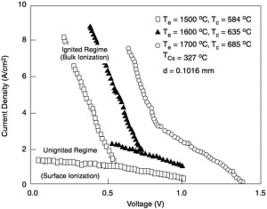
FIGURE 3.4 The current-voltage curve of a typical thermionic converter. Te, emitter temperature; Tc, collector temperature; TCs, cesium reservoir temperature; d, electrode spacing.
power conversion system, as detailed in this section. However, the success of such a system will depend entirely on technologies that have not yet been developed. Chapter 4 details the advantages of a lightweight solar thermionic system if lightweight power conditioning electronics, a lightweight concentrator, a high temperature receiver, and a heat pipe radiator can be developed. Potential missions for thermionic power systems are listed in Table 3.1.
A lightweight power system with minimum volume is desirable for launch purposes. The approximate cost to launch a spacecraft is $6,000 to $10,000 per kilogram to reach low Earth orbit (LEO) and $20,000 to $40,000 per kilogram to reach a geosynchronous Earth orbit (GEO) depending on the launch vehicle type. Making the power conversion system smaller increases the volume and mass allocation available for mission payload on the launch vehicle.
Many other energy conversion systems have been explored to satisfy potential requirements for space-based power systems. Currently, there is little consensus within the power technology community on which power conversion system would be best for missions that travel beyond Mars or toward the Sun inside the orbit of Venus. There is very clear consensus that solar arrays are the best power conversion technology to use for spacecraft orbiting Earth or traveling to Mars and Venus.
Thermionics has also been considered for Earth-based, or terrestrial, power generation systems, but to a much lesser extent. These systems would convert thermal energy to electrical energy using a thermionic conversion device. The ability of thermionic devices to operate at higher temperatures than conventional turbine engines might make thermionics attractive for niche applications.
The following sections describe general applications for thermionics and contrast thermionic power conversion with competing technologies that achieve the same goal.
Space Power Applications
Almost all space missions to date have required some form of power onboard a spacecraft. The amount of power needed by these missions in the past, present, and future varies widely depending on the mission. Spacecraft operate as close as low Earth orbit, only
TABLE 3.1 Potential Missions for Solar and Nuclear Thermionic Power Systems
|
|
Mission |
|||||||
|
|
Near-Term, Space-Based Radar |
Far-term Space-Based Radar |
Space Transportation/ Electric Propulsion |
Manned Space Exploration |
Lunar, Planetary Surface Power |
Advanced Communications |
Space-Based Electric-powered Weapons |
Advanced Deep Space Telescope |
|
Power required (kW) |
3 to 10s |
100s |
5 to 100s |
100s to 10 MW for cargo support missions |
100s to 1,000s |
10s to 100 |
1,000s |
10s to 100 |
|
Location |
LEO |
High orbit |
Orbit transfer, deep space |
Mars to deep space |
Lunar and planet surface |
LEO to GEO |
LEO to GEO |
LEO |
|
Application for solar thermionics |
√ |
√ |
√ Orbit transfer and deep space |
√ Cargo and robotic missions |
|
√ |
√ |
√ |
|
Application for nuclear thermionics |
|
√ |
√ Deep space |
√ Manned missions |
√ |
|
√ |
|
hundreds of miles above Earth’s surface, and as far away as the outer planets and beyond. In the future, space missions may include a lunar base and a human mission to Mars.
The power required for spacecraft ranges from watts to tens of kilowatts today and may require hundreds of kilowatts, even megawatts, in the future. The length of time that peak power is required also depends on the mission type. Some missions may require a few seconds burst of high power, while other missions may be conducted for decades, requiring continuous power for the entire mission life.
A variety of power system technologies can be used to satisfy this broad range of needs. Figure 3.5 depicts the general applicability of a particular power system to a given power level and mission duration regime. The separate areas shown in the figure represent the areas where different power conversion technologies have the greatest benefit. For example, chemical systems, such as primary single use batteries, fuel cells, and combustion turbo alternators, are useful for relatively short lived missions. Solar photovoltaic systems using rechargeable batteries are in wide use today. Solar-heated, dynamic conversion systems are rarely used and are based on different thermodynamic cycles, such as the Brayton, Rankine, and Stirling cycles, and alkali metal thermal electric converters (AMTEC) and thermionic converters. Finally, nuclear reactor- and radioisotope-heated dynamic and direct converters are listed. Thermoelectric and thermionic systems fall in this final category.
The shape of the boundaries between areas varies depending on the importance of power system mass, volume, cost, reliability, and system integration issues. Safety issues and other power system selection criteria can also affect the boundaries of the areas in Figure 3.5.
Figure 3.6 groups similar candidate power systems together in relation to their applicable regimes, showing selection criteria for one type of power system. Power system specific mass, defined as total mass divided by total power produced, is plotted versus power output for mission durations in the 5 to 10 year range. These optimum specific mass regimes were determined by plotting the results of the many space power system design studies conducted between 1960 and the 1990s.
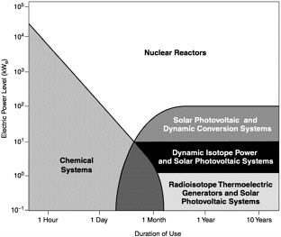
FIGURE 3.5 Power system options for specific mission durations.
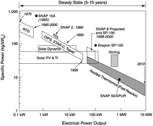
FIGURE 3.6 Inverse specific mass versus electrical power output.
Figure 3.6 demonstrates the wide potential applicability of both nuclear-heated thermionic systems and, to a lesser extent, solar-heated thermionic systems. The ability to scale these technologies to larger power systems is also important.
Over the past four decades, several design studies considered thermionics as the power source. Generally, the main advantage of both nuclear and thermionic systems is their potential for high specific power, particularly at high power output levels. By contrast, radioisotope thermoelectric generators are not generally scalable above 1 kilowatt due primarily to high fuel costs and limited supply of isotopes. Some have suggested that by using more efficient dynamic converters coupled to radioisotope heat sources, those heat sources could be expanded to supply 1 to 2 kilowatts of power. However, these changes would introduce life and reliability issues that would require more investigation.
The highly modular nature of thermionic converters represents a potentially significant, yet subtle, cost benefit when establishing a reliability database as compared to dynamic conversion devices. This situation is also true for the equally modular photovoltaic cells. However, there is a cost penalty on the front end to develop thermionic systems for in-core thermionic fuel elements. The cost of testing in-core for issues such as fuel swelling and radiation effects on materials can be significant.
Solar dynamic power systems were included in the early International Space Station (ISS) design. These power systems were ultimately not pursued, in part because the dynamic converters themselves were not fully developed and lacked a significant life test database. The ISS development team selected photovoltaic battery systems, accepting, when they did so, the tradeoff between the perceived lower technical risk associated with a proven technology despite the potential limitation, at that time, of not being able to scale photovoltaics up to the 75 kilowatts power requirement. Also, maintenance issues on dynamic systems were a concern. However, the team was limited in its choice since there were no other flight-demonstrated power conversion technologies available that had the promise to achieve such power levels.
The data shown in Figure 3.6 exclude any out-of-core nuclear thermionic concepts, whose application overlaps the application of in-core thermionic systems. Also, the ability of some categories of nuclear out-of-
core systems to scale to high power levels is limited compared to that of nuclear in-core systems.
Most of the specific power advantages of nuclear thermionics are a result of the converter’s potential ability to operate within a nuclear core. When manufactured as part of a nuclear fuel rod, the thermionic converter can eliminate both heat transport temperature drops and the need for additional heat transport hardware to convey the heat from the core to the converter. A thermionic energy converter is the only converter, static or dynamic, that has been designed to operate inside a nuclear core. This benefit allows the overall power generation system to be more compact and potentially less complex.
However, there are also issues with materials and fuel swelling. The high temperature, electric field, and radiation environment inside the nuclear core can severely affect the lifetime of materials. Also, as fission gas products build up inside the reactor, the nuclear fuel swells and mechanically stresses the containment walls. If the nuclear fuel is part of a thermionic fuel element (TFE), the resulting mechanical deformation can cause an electrical short in the TFE.
All power system cooling in space is usually accomplished by radiative cooling. Therefore, the high heat rejection temperature associated with thermionics gives the system another benefit. The high heat rejection temperature allows for a compact, lightweight radiator. As system power levels increase, the mass of the thermal radiator scales linearly with power, and as the reciprocal of the absolute temperature raised to the fourth power.2 As a result, as the power level increases on a traditional space-based nuclear reactor, the radiator becomes a significant contributor to the total system mass.
With a thermionic nuclear reactor system, however, the high heat rejection temperature allows for a smaller heat rejection radiator to be used. Even when compared to most other nuclear power conversion candidate technologies that operate outside the nuclear core yet have higher efficiencies, a nuclear in-core thermionic system is still often more desirable in terms of specific mass. For example, a thermionic system operating at 10 percent efficiency must reject 125 percent more heat than a 20 percent efficient dynamic nuclear power system, such as a Brayton, Rankine, or Stirling dynamic converter. However, the dynamic converter rejection heat radiator must be nearly an order of magnitude larger owing to the inverse fourth power scaling of radiator area as a function of temperature. As a result, dynamic nuclear power system radiators are not readily scalable to very high power levels. At megawatt power levels, the mass of the heat radiator would most likely dominate system mass. Another way to view this situation is that the thermionic system takes advantage of the temperature to the fourth power rule by using a higher heat rejection temperature and a smaller radiator.
When scaling a nuclear reactor core to provide more heat, a fairly small increase in the overall size of the core will yield significant results since the mass of a cylindrical core simply scales in proportion to the radius squared. An increase in core size therefore yields more heat energy to drive a thermal conversion system. All reactor systems, when looking simply at the nuclear core, scale easily to supply larger amounts of heat energy, which in turn can provide more thermal power.
However, the peripheral hardware of the converter systems receiving the thermal output from the nuclear reactor scale more linearly with the increase in overall heat energy, so that scaling to higher energy power systems results in an unfavorable increase in overall system mass.
This high temperature heat rejection characteristic allows thermionic system radiators to be intrinsically compact. A future thermionic system could have mass and payload integration advantages over most power conversion candidates. The notable exception is the liquid metal Rankine cycle, which also rejects heat at a high temperature. Development of liquid metal Rankine cycles ceased in the 1970s, at a low level of development, with the demise of the U.S. space nuclear power program.
Another intrinsic advantage of thermionic system radiators used in space, relative to low temperature systems, is the potential ability of the thermionic radiator to survive a small meteoroid impact as well as attack by space-based weapons that use high speed orbiting pellets, laser systems, or other potential threats. The radiator system has higher survivability because it can be more easily armored and constructed to be highly redundant through the use of heat pipes in case parts of the radiator system are disabled. The armoring can be added to the high temperature system with a much smaller mass penalty than a low temperature system would incur. To armor a larger radiator system that is
used on low temperature systems is much less feasible because of the additional mass that armoring would add to the overall system. Also, the smaller size of a high temperature thermionic radiator decreases the probability of the system being hit. These potential survivability advantages apply only to other comparable high temperature systems. A complete discussion of survivability is beyond the scope of this report.
A less obvious thermionic radiator advantage not shared by its lower temperature competitors is the ability of a thermionic system to use sodium heat pipes for radiator heat transport. In addition, the temperature range of a thermionic system is nearly optimal for sodium heat pipe operation. Selection of an adequate radiator heat pipe fluid for 500 to 600 K radiators is difficult, but is often ignored when considering low temperature systems. A sodium heat pipe has a very high transport capacity, which allows for a lighter weight and less complex radiator assembly.
Finally, the power density that can be attained by a thermionic converter system as the temperature of the system increases is very impressive. The device output increases exponentially with only moderate increases in temperature on the order of a few hundred degrees and with minimal technical risk. This increase in device power density as a function of temperature is shown in Figure 3.7.
The very high temperature thermionic regime shown in Figure 3.7 reflects U.S. and Russian experimental data. The data demonstrate that thermionics potentially offers a tenfold gain in power density compared to current technology if higher temperature fuels, more creep resistant electrode materials, and fuel cladding materials can be developed. The advantage of higher system power density is that, again, an overall lighter system is possible than with current systems. However, Figure 3.7 does not take into account lifetime issues that need to be resolved to make thermionics a viable system-level technology.
There is a potential limit on the ability of solar photovoltaic and other solar concentration approaches to scale to very high power scenarios. The area of solar
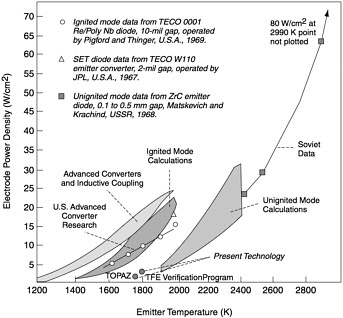
FIGURE 3.7 Increase in power density of a nuclear thermionic system as a function of temperature.
array and concentrator systems scales roughly linearly with power; however, the structural mass to support the array or concentrator does not. The increase in the mass required to support such a structure for very high power levels might not be practical for launch unless there are unforeseen advances in lightweight structural materials.
Most experts in the power system community acknowledge that there is a maximum limit for solar power systems; however, that exact practical limit is not known. Nuclear thermionic systems offer reduced mass, volume, and surface area, which may become increasingly important when space power needs approach and exceed 100 kilowatts. Nuclear thermionics has the potential to scale to these higher powers, where, as discussed in the next section, they could be very useful for specific space missions.
A unique benefit for electric propulsion systems is that nuclear powered and some solar powered thermionic systems, designed to operate over normal capacity at the beginning of the system’s operational life, can operate in a surge power mode (also referred to as peak power mode). For example, in the regime shown in Figure 3.7, the emitter temperature can be increased from 1800 K to 2100 K to double the power for a relatively short time of 30 to 90 days. To configure a system to operate in a surge mode requires that all components be designed to achieve equilibrium at a higher temperature. This type of operation also requires spacecraft designers to accept a somewhat shorter vehicle operating lifetime. Such surge mode operation can be used to decrease the time required for orbit positioning or transfer. In this dual mode operation, electric propulsion can be combined with other mission requirements resulting in a synergistic benefit. This operational scenario is described in more detail in Chapter 4.
Key Finding: Thermionic systems are unique for three reasons: (1) the inherently high power density of the conversion mechanism itself, (2) the systems’ high heat rejection temperature, typically 1000 K, which allows thermionic systems to use compact radiators with relatively low masses, and (3) the systems’ potential to operate in a higher power “surge mode” for sustained periods over a small fraction of their programmed life. The combination of these three advantages could allow for potentially significant advances in system power level density (kilowatts per kilogram).
Comparison of Thermionics with Other Power Conversion Technologies
The location of thermionic technology within the spectrum of space energy conversion systems can be determined only by comparing and contrasting it with the other available and emerging technologies. Eight commonly discussed technologies have supplied spacecraft with power or offer the potential to do so in the future. Of the eight, only five have actually been flown in space. These flight demonstrated power conversion technologies are compared in Table 3.2.
The power conversion systems that have flown on spacecraft are listed below:
-
Photovoltaic—Systems are still in widespread use;
-
Radioisotope thermoelectric generator (RTG)— Used infrequently;
-
Fuel cells—Still in use for specialized, short duration missions such as the space shuttle;
-
Thermoelectric nuclear reactor—Used in up to 30 Russian spacecraft and 1 experimental U.S. spacecraft, but no longer in use; and
-
Thermionic nuclear reactor—Used in two Russian missions in the late 1980s, but no longer in use.
The systems that are in development but have not flown in space are as follows:
-
Dynamic (solar or nuclear), including Rankine, Brayton, and Stirling cycle converters;
-
Alkali metal thermal to electric converters (AMTEC; see Box 3.1);
-
Magnetohydrodynamic (MHD) converters.
Photovoltaic systems with battery storage are the most commonly flown space power systems. They have been in use since the late 1950s and have flown on more than a thousand missions. Systems have been designed to supply up to 75 kilowatts of electricity and for up to 15 years of life.
A second power conversion technology to be placed in space is the radioisotope thermoelectric generator. RTGs are small devices designed to supply less than 1 kilowatt for greater than 10 years. These devices have been used on deep space probes, as well as on several long-life instruments left on the Moon during the Apollo program. RTGs have also been used extensively in the Russian space program.
TABLE 3.2 Comparison of Flight Demonstrated Power Conversion Technologies
|
|
Beginning of Life |
|
|||||
|
Technology |
W/kg |
kg/kW |
Power Level (kW) |
Recurring Cost ($/Watt) |
Year |
Life (yr) |
Comments |
|
14.85 |
67.36 |
10 |
1,130 |
|
|||
|
Solar arrayc |
50.00 |
20.00 |
|
700 |
2000 |
15 |
Must have sunlight |
|
Battery (kWh/kg) |
19.50 |
51.28 |
|
180 |
1999 |
15 |
Must have electric energy storage |
|
PV conditioning |
481.06 |
2.08 |
|
250 |
2000 |
15 |
Good between Mars and Venus |
|
electronics |
|
Degrades 1–2%/yr, sensitive to radiation Deep Space 1, Hughes 702 Battery is 30% DoD 60 kWh/kg NiH2 SPY |
|||||
|
5.30 |
188.68 |
0.3 |
133,000 |
1997 |
30 |
Highly survivable against natural radiation and space-based weapon attacks |
|
|
Radioisotope |
|
plus Pu238 |
|
||||
|
thermoelectric |
|
Heat source degrades 0.8%/yr from Pu238 half-life |
|||||
|
generator (RTG) |
|
Converter degrades 0.8%/yr Cassini |
|||||
|
Fuel cells (alkaline)f |
51.00 |
19.61 |
7 |
825 |
1981 |
0.3 |
Requires fuel resupply |
|
Fuel (Wh/kg) |
1550.00 |
0.65 |
|
plus fuel |
|
Requires fuel storage, tank weight included Does not need sunlight Orbiter Requires maintenance between flights |
|
|
Nuclear thermionicg |
4.17 |
239.81 |
5 |
5000 |
1987 |
1.0 |
Highly survivable |
|
|
plus fuel |
|
Cosmos 1818 and 1867, Topaz I |
||||
|
a0.56 watt-hours of energy storage required for every watt of load power needed in a low Earth orbit (LEO). b1.75 watts of solar array power required for every watt of load power needed in a LEO. cAllen, Douglas M., and D.M.Murphy. 1998. “An Update on the Deep Space 1 Power System: SCARLET Integration and Test Results,” Proceedings of the 33rd Intersociety Engineering Conference on Energy Conversion, American Nuclear Society, Albuquerque, N.Mex., August 2–6, 1998. dMehner, Arthur, U.S. Department of Energy, e-mail communication, July 28, 2000. eBennett, Gary, e-mail communication, July 15, 2000. fLoyselle, Patricia, Thomas Maloney, and Henry Cathey, Jr. 1999. “Design, Fabrication, and Testing of a 10 kW-hr H2-O2 PEM Fuel Cell Power System for High Attitude Balloon Applications,” 34th Intersociety Energy Conversion Engineering Conference Proceedings, Society of Automotive Engineers, Inc., August 1999. gNational Research Council. 1996. Assessment of TOPAZ International Program. Committee on the TOPAZ International Program. National Academy Press, Washington, D.C. |
|||||||
The third power conversion system to have been used in space is the fuel cell. Fuel cells are typically used for short duration missions. They are compact systems with no deployed devices such as photovoltaic arrays although small waste heat radiators are sometimes used. Fuel cells combine aqueous hydrogen and oxygen to yield water as a waste product. These systems have been used on manned space flight programs since the early days of those missions and are still in use today on the space shuttle.
Nuclear thermionic generators are the only other power conversion devices to have been flown on operational spacecraft. Two Russian experimental satellites, Cosmos 1818 and Cosmos 1867, used thermionic conversion systems to supply their power. Cosmos 1818 and 1867 operated in space for approximately 142 days and 342 days, respectively (Ponomarev-Stepnoi et al. 2000).
Ground demonstration is one technology development step below flight testing. This development level is for technologies that are not mature enough for space flight, but it is intended to demonstrate the promise of a new technology in a flight-like configuration and environment. Other heat engine systems in addition to static
|
BOX 3.1 Alkali metal thermal to electric converters (AMTECs) are thermally powered electrochemical concentration cells that convert heat energy directly to DC power from any fuel source capable of generating 970 to 1170 K. The converter has no moving parts and efficiencies ranging from 15 to 25 percent depending on operating temperature and specific design features. In operation, an alkali metal such as sodium or potassium ionizes and is driven through an ion-permeable beta-alumina solid electrolyte membrane by a temperature-induced pressure differential. On the cathode at the low pressure side, the alkali metal evaporates, travels as a vapor to a heat sink where it condenses, and then is returned to the high pressure zone by a fine capillary artery or an electromagnetic pump. The charge separation produces electrical power at the anode and cathode surfaces of the ceramic membrane. With its moderate upper operating temperatures and heat sink temperatures from 373 to 623 K, AMTEC is suitable for cogeneration or topping cycle applications. Thermodynamically, AMTEC operates as a heat engine. However, in contrast to Stirling, Brayton, and Rankine dynamic cycles, AMTEC systems have no moving parts and are temperature sensitive but relatively insensitive to the choice of heat source. |
AMTECs that have been ground demonstrated include the dynamic Brayton cycle, the Rankine cycle with an organic working fluid, and the Stirling cycle. However, these systems have not flown or been demonstrated in a flight configuration or adequately life tested. Table 3.3 compares some of the ground demonstrated power conversion technologies.
The least mature level of development is projected performance based on theoretical or partially demonstrated performance. Closed cycle MHD falls into this category. There have been several planned MHD ground demonstrations, but these tests were for terrestrial systems, not space flight systems. The technology is being considered for possible use on future orbit-raising vehicles that move satellites from low Earth orbit to geosynchronous Earth orbit. Table 3.4 characterizes the advances projected to be made with power conversion systems.
There are five top-level criteria that a systems engineer considers when selecting a technology as a power source for space flight:
-
Weight,
-
Cost,
-
Volume needed on the launch vehicle,
-
Deployed area or boom length, and
-
Risk and availability.
These criteria must be well defined before choosing a power source. The availability of sunlight is another key issue and one that is mission specific, which generally relates to what energy sources are available where a mission is to operate. Some missions may operate where there is little to no usable sunlight, such as around the outer planets. Where no sunlight is available, a nuclear heat source is most likely the only option available to power a spacecraft. This option requires a heat-to-electric converter such as thermoelectric, thermionic, AMTEC, or a heat engine using a Brayton, Rankine, or Stirling cycle.
Yet another set of missions to which nuclear power may be best suited are missions that very closely approach the Sun, where the vehicle must contend with extreme heat and very intense solar conditions.
HISTORY OF THERMIONIC SYSTEMS AND DEVELOPMENT
The ability of a device to supply usable electrical power from heat, thus converting the heat energy to electrical power with no moveable mechanical parts, is a potentially important process. One sure process, thermionics, has been investigated as a potential power supply since the 1950s by many different individuals and companies. To make clear the extent of the research carried on in thermionics to date, this section describes previous efforts to develop thermionic power systems and highlights the major accomplishments of each project.
Early efforts, beginning in the 1960s, involved both solar and nuclear in-core reactor system configurations. Solar thermionic developments were abandoned in the early 1970s, while nuclear thermionic research continued sporadically from the 1960s through the 1990s.
Jet Propulsion Laboratory Solar Energy Technology (SET) Thermionic Program
JPL initiated a solar thermionic converter life evaluation and generator test program in 1961. The activities taking place under the SET program included the following:
-
Performance testing on over 135 thermionic converters;
TABLE 3.3 Comparison of Ground Demonstrated Power Conversion Technologies
-
Extended life testing on 10 planar converters for a total of over 68,000 hours from 1967 to 1969, with converters experiencing hundreds of thermal cycles;
-
Building of at least four generators with four-converter configurations and testing them calorimetrically in the laboratory; and
-
Testing of the four-converter generator geometry with a Sun tracking, 9.5 foot diameter parabolic mirror.
Most SET converters were tested in the 1900 to 2000 K emitter temperature range, with life routinely exceeding 7,000 to 11,000 hours while maintaining efficiencies between 7 and 10 percent. One converter test had a demonstrated life of 20,000 hours, or 2.3 years, while producing 25 watts per square centimeter on the converter surface. The converter in question experienced less than 5 percent power density degradation. The 150 watt generators in the SET program demonstrated efficiencies in the range of 9 to 11 percent, while operating at approximately 1700 K. The converter power densities ranged from 17 to 22 watts per square centimeter. The SET program was terminated in the early 1970s.
The committee found that researchers working under the U.S. Air Force and DTRA String Thermionic Assessment Research Testbed program, as discussed in Chapter 7, had difficulty trying to recapture the generator design and test experience from the SET program work.
The Atomic Energy Commission’s Thermionic Reactor and Fuel Element Programs
The Atomic Energy Commission (AEC), which was replaced by the Department of Energy (DOE), initially ventured into thermionic development in 1959, funding the Los Alamos National Laboratory. In 1964, the AEC began funding General Electric and General Atomics to develop an integrally fueled thermionic fuel element. In 1970, General Atomics was selected to continue development of the thermionic fuel element and to construct a thermionic test reactor. The program included designing thermionic power systems for both space and remote terrestrial applications, as well as developing fabrication methods for single-cell and multicell thermionic fuel elements and a thermionic critical reactor experiment. A test reactor at General Atomics (TRIGA), the Mark III thermal spectrum
TABLE 3.4 Comparison of Projected Power Conversion Technology Capabilities
|
|
Beginning of Life |
|
||||
|
Technology |
W/kg |
kg/kW |
Power Level (kW) |
Recurring Cost ($/Watt) |
Years to Maturity |
Comments |
|
33.65 |
29.7134 |
|
633 |
|
Assumes a 500 nm (926 km) orbit with a 33 min eclipse |
|
|
Solar arrayd |
200.00 |
5.00 |
30 |
300 |
5 |
35% efficient solar cells on communications satellite |
|
Battery (30.0 Wh/kg) |
54.55 |
18.33 |
|
133 |
|
30% depth of discharge at 100 Wh/kg lithium-ion battery |
|
PV conditioning electronics |
665.00 |
1.50 |
|
200 |
|
|
|
Thermoelectric RTGd |
8.00 |
125.00 |
TBR |
Unknown |
20 |
Costs do not include plutonium-238 |
|
181.00 |
5.52 |
20 |
Unknown |
7–10 |
Potential life increase to 1.14 years |
|
|
Fuel (Wh/kg) |
1550.00 |
0.65 |
|
Power density may be as high as 1000 W/kg and 2500 Wh/kg |
||
|
31.15 |
32.10 |
|
Assumes a 500 nm (926 km) orbit with a 33 min eclipse |
|||
|
Thermionic converteri |
106.00 |
9.43 |
50 |
Unknown |
10 |
|
|
Thermal storagej |
48.64 |
20.56 |
|
133 |
|
90% depth of discharge at 213.9 Wh(thermal)/kg manganese oxide |
|
Control electronics |
665.00 |
1.50 |
|
200 |
|
|
|
Concentrator massk |
600.00 |
1.67 |
|
|||
|
Nuclear thermionicd |
33.78 |
29.60 |
100 |
Unknown |
7–10 |
|
|
Solar dynamic |
|
|||||
|
11.50 |
86.96 |
10 |
2,500 |
5 |
|
|
|
15.00 |
66.67 |
10 |
|
5–10 |
|
|
|
Nuclear dynamic |
|
|||||
|
40.00 |
25.00 |
100 |
Unknown |
5–10 |
|
|
|
100.00 |
10.00 |
1,000 |
|
10–20 |
|
|
|
8.00 |
125.00 |
0.1 |
20,000 |
5 |
Costs do not include plutonium-238 |
|
|
10.00 |
100.00 |
1 |
|
5–10 |
|
|
|
30.00 |
33.33 |
100 |
|
10–15 |
|
|
|
AMTEC |
|
|||||
|
Radioisotope AMTECn |
11.20 |
89.29 |
0.1 |
Unknown |
5 |
|
|
Solar AMTECo |
49.00 |
20.41 |
3 |
Unknown |
10–15 |
|
|
aThere is a requirement for 0.56 watt-hours (Wh) of energy storage for every watt of load power needed in a low Earth orbit (LEO). bThere is a requirement for 1.75 W of solar array power for every watt of load power needed in a LEO. cThere is an array scaling factor of 1.75 included in the calculation of the specific power to accommodate required battery recharge energy, recharge efficiency, and electrical bus power conditioning efficiency. dSovie, Ronald J. 1999. Space Power Systems Technology to Meet National Needs. American Institute of Aeronautics and Astronautics, Reston, Va. eLoyselle, Patricia, Thomas Maloney, and Henry Cathey, Jr. 1999. “Design, Fabrication, and Testing of a 10 kW-hr H2-O2 PEM Fuel Cell Power System for High Altitude Balloon Applications,” 34thIntersociety Energy Conversion Engineering Conference Proceedings, Society of Automotive Engineers, Inc., August 1999. fBradley, Karla F., Johnson Space Center, telephone and e-mail communication, 2000. gFellner, Joe. 2000. “Electrochemical Power/Energy Storage for Diode Lasers,” Proceedings of the 13thAnnual Solid State and Diode Laser Technology Review. Air Force Research Laboratory, August. hThere is a requirement for 1.73 W of thermionic converters for every watt of load power required in a LEO. iBegg, Lester, General Atomics, presentation to the committee, 2000. jAssume 213.8 Wh (thermal)/kg manganese oxide, 15% thermionic converter efficiency, and 20% penalty due to structure, insulator, and heat exchanger mass. kAssume 80% inflatable concentrator optical efficiency, 0.27 kg/m2 for inflatable concentrator, which includes the torus, reflective canopy, inflation system, and pointing and tracking hardware. lMason, Lee S. 1999. Technology Projections for Solar Dynamic Power. NASA TM-1999–208851. NASA, Washington, D.C. mMason, Lee S. 2001. A Comparison of Brayton and Stirling Space Nuclear Power for Power Leads from 1 Kilowatt to 10 Megawatts. NASA TM-2001–210593. NASA, Washington, D.C. nSchock, A., H.Noravian, C.Or, and V.Kumar. 1999. “Recommended OSC Design and Analysis of AMTEC Power System for Outer-Planet Missions,” Space Technology and Applications International Forum. American Institute of Physics, Melville, N.Y. oHunt, Thomas, Advanced Modular Power Systems, Inc., e-mail communication, March 14, 2001. |
||||||
nuclear reactor, was built that was capable of testing up to 15 in-core thermionic fuel elements simultaneously. The chain reaction of the TRIGA reactor is sustained primarily by thermal neutrons, those fast neutrons that have collided with other material in the core to achieve a lower energy state. Thirty-seven thermionic fuel elements were tested in-core between 1962 and 1973. Converters operating at full power at 1900 K in the nuclear core achieved lifetimes of 12,500 hours. The program was terminated in 1973, when all AEC, NASA, and DoD activities related to space nuclear reactors were discontinued. To date, the DOE, and the AEC before it, have invested over $1.5 billion in nuclear reactor programs such as SNAP-2, SNAP-10A, SNAP-50, and SNAP-8, and in other reactor and dynamic energy converter programs. Nuclear thermionic activities were also included in these programs. At the conclusion of the nuclear program in 1973, only NASA Lewis Research Center continued to fund thermionic research. However, that organization terminated thermionic research in the late 1970s. For a detailed history of the space nuclear energy program, see NRC (1983).
The SP-100 Program and the Thermionic Fuel Element Verification Program
From 1973 to 1979, the national space nuclear power program conducted very little research and development, and the USAF, NASA, and DOE allocated very little funding for thermionic technology development. In addition, NASA Lewis abandoned its in-house thermionic research facility and its considerable thermionic materials development program.
In 1979, a joint DoD and Energy Research and Development Administration (ERDA) study group assessed potential DoD missions. That assessment led to a modest $1 million to $2 million per year technology program at Los Alamos National Laboratory. The program at Los Alamos focused on a heat pipe cooled thermoelectric concept called the space power advanced reactor (SPAR). Other advanced reactor types were also investigated by DOE, but at low levels of effort.
In 1981, NASA agreed to collaborate with DOE on reestablishing a high power space nuclear reactor program. NASA’s interest was based on several potential missions that would require 100 kilowatts or more of electrical power. This power range was the same as the range DoD was interested in at the time. As a result of the combined interest, the SPAR program was redirected and renamed SP-100 when DoD joined the program. DOE led the reactor development effort, and NASA coordinated efforts on the power conversion and radiator development. NASA was not considering thermionics at the time. In 1983, the Defense Advanced Research Projects Agency (DARPA) joined the SP-100 program as the DoD representative to the triagency group composed of DOE, DoD, and NASA. DARPA was replaced by the Strategic Defense Initiative Office (SDIO) in 1986.
When a ground engineering system development effort was initiated, candidate reactor power systems for full development included thermionics, thermoelectrics, Brayton cycle, and Stirling cycle configurations. The thermoelectric system was selected partly in the belief that a reactor developed for the relatively low temperature thermoelectric system would also apply to the Brayton and Stirling cycle configurations as those two technologies matured. After considerable discussions with the thermionics community, SDIO, in conjunction with DOE, began an adjunct thermionics program to the SP-100 program. This second program was aimed at verifying the potential of the in-core thermionic reactor to satisfy envisioned SDIO missions, which extended into the megawatt power requirement regime. The program was named the Thermionic Fuel Element Verification (TFEV) program.
Based on the past accomplishments of the DOE thermionic fuel element program, the life of thermionic reactors was projected to be about 1 year. The objectives of the TFEV program were established to address this life limitation. Researchers understood that the life limits were related to fuel swelling. Fuel swelling is caused by the accumulation of fission gas in the bulk fuel, which distorts the emitter and eventually results in an electrical short between the emitter and collector surfaces of the fuel elements. Radiation damage on materials was also a concern. Accordingly, the TFEV program had the following largely experimental demonstration and evaluation goals:
-
Predictive fuel swelling and emitter distortion validation;
-
Assessment of radiation damage and effects on insulators, seals, and cesium reservoir materials; and
-
Revalidation of prior test data on thermionic fuel element life obtained in the neutron flux TRIGA thermal reactor.
A variety of candidate insulator, seal, and cesium reservoir materials were tested in a fast reactor radia-
tion spectrum. In some cases, the materials were subjected to accelerated testing to the equivalent of 15 years of life. Multiple in-core, fueled emitter tests were conducted to validate fuel swelling, fission gas liberation rates, and the resultant clad distortion predictions.
Polycrystalline alumina proved to be sufficiently stable at high temperatures and electric fields to perform as a thermionic insulator and seal material for 7 to 10 years. Graphite proved to be an adequately stable cesium reservoir matrix material. At a temperature of 1800 K, computer models were able to predict a consistent relationship between fuel swelling and emitter distortion when up to 2 percent of the nuclear fuel atoms had fissioned. This was twice the system design requirement.
Thermionic fuel element manufacturing methods were recovered from work conducted 15 years earlier. The fast spectrum, nuclear thermionic fuel element was demonstrated to last up to 12,000 hours, and projected to last to 18,000 hours based on observed distortions. Contamination of the cesium interelectrode gap by fission gas resulted in acceptable degradation. The TFEV program validated the potential of in-core thermionic reactor systems to meet mission life requirements ranging from 3 to 7 years, and there were indications that longer life might be possible.
Russian Thermionics Research and Development Efforts
Efforts in the former Soviet Union have contributed greatly to the technology of thermionic energy conversion and to space nuclear power in general. The former Soviet space program has flown more than 30 thermoelectric reactor systems and at least 2 thermionic reactor systems. By contrast, the United States flew only one nuclear reactor, SNAP-10A, in 1965.
In contrast to the U.S. program, the Soviet thermionics reactor capability has been supported by a diverse, broadly based technology program that resulted in the launch of two spacecraft. The major research groups working on the technology in the former Soviet Union were the following:
-
Russian Research Institute Kurchatov,
-
Institute of Physics and Power Engineering at Obninsk,
-
Scientific Production Association Red Star,
-
Scientific Production Association Energiya,
-
Scientific Research Association Luch,
-
Central Design Bureau for Machine Building,
-
Sukhumi Physical Technical Institute,
-
Ioffe Physical Technical Institute, and
-
Institute of Nuclear Physics at Almaty.
Major development was carried out in a number of areas, including the nucleonic theory of compact thermionic space reactor design, the control theory of nuclear thermionic reactors, high temperature materials, high temperature nuclear fuel, single-crystal refractory metals, radiation degradation studies, and thermionic converter physics. These programs are impressive in terms of their breadth, as well as their depth in demonstrating the feasibility of space nuclear thermionic systems.
While the United States has made impressive strides in photovoltaic research that the Russians have not matched, the former Soviet Union did produce many noteworthy technical achievements in thermionic technology. Specific areas in which the former Soviet Union appears to have outstripped the U.S. efforts are detailed below.
Single-Crystal Refractory Metal Alloy Development
Several thermionic single-crystal emitter alloys were successfully developed in the former Soviet Union, including alloys of tungsten and molybdenum. No such capability existed in the United States until after 1990. The principles of single-crystal alloy production were well known in 1990 in the United States because single-crystal technology in other alloy systems had been extensively investigated in connection with high performance aircraft engines. However, researchers in the United States never considered the single-crystal refractory metal series for use in thermionics. Since single-crystals have no grain boundaries, using alloys of single-crystal material for high temperature thermionic emitter cladding is believed to limit diffusion of unwanted materials through the emitter cladding.
Low Elastic Modulus Nuclear Fuel to Accommodate Fission Gas Swelling
The U.S. philosophy in reactor design has generally been to use high modulus nuclear fuels to resist emitter cladding swelling induced by fission product gases. Emitter swelling can be a life-limiting degradation mechanism in an in-core thermionic reactor. The Russian approach has been to vary the stoichiometry of
uranium and oxygen to minimize the modulus of the fuel. In this way, the nuclear fuel plastically deforms to accommodate the change in cladding geometry. In addition, Russian thermionic fuel elements are designed to vent the fission gas. As a consequence, the fuel is unable to exert force on the cladding wall, and emitter clad distortion is minimized (Gontar 1990).
Resistively Heated High Temperature Refractory Metal Heat Source Development
In the United States before 1990, it was assumed that thermionic nuclear power systems would be launched without any prior acceptance testing of the complete flight unit power system since such prelaunch testing creates radioactive fission products, thus complicating safe launch procedures. Later, Russian researchers demonstrated that a system could be tested using non-nuclear heating. By testing the converter system using electrical heating, researchers could acceptance-test a thermionic converter system on the ground without having to address the added complexity of using nuclear fuel. Refractory metal heaters, such as those developed by the Russians, allow a thermionic system to be tested electrically.
Because U.S. thermionic reactor advocates had not appreciated the benefit of refractory metal heat sources for acceptance testing on the ground, they did not work to develop such sources. Russian researchers, on the other hand, paid considerable attention to qualifying and partial acceptance testing (electrical heating only) on Earth and worked to develop refractory metal heat sources (Vybyvanetz et al. 1990).
Stainless Steel Containment of Zirconium Hydride Moderator
A significant difference between Russian and U.S. reactor design philosophy concerns the use of a neutron moderator. The Russian preference has been to use a neutron moderating material, such as zirconium hydride. The use of such a material results in a more compact nuclear reactor core and shield and dramatically reduces the critical mass of enriched uranium required. The thermal reactors can reach critical mass with as little as 10 to 12 kilograms of fuel, whereas most fast reactor cores require well over 100 kilograms. The thermal stability of zirconium hydride is limited, however, since the hydrogen tends to dissociate from the zirconium at high temperatures. If the hydrogen were allowed to diffuse into the thermionic converter interelectrode gap, a rapid corrosion cycle or embrittlement could occur. High temperature diffusion barrier coatings have evidently been used to prevent hydrogen diffusion into the thermionic converter, but such work has not been pursued in the United States.
Single-Crystal Sapphire Thermionic Insulators
The use of single-crystal sapphire as a thermionic insulator was virtually unknown in the United States prior to 1990. Because there are no grain boundaries in the insulator, electrolytic transport is greatly reduced. As a result, such insulators are considered to be more stable under the combined effects of high temperature, electric fields, and radiation.
Single-Crystal Hexagonal Tungsten Thermionic Emitter Elements
This technology has been demonstrated only in the laboratory and not in operational systems. The hexagonal shape, as opposed to the customary cylindrical shape, permits the emitter to exhibit only the 110 crystal plane. This orientation may increase electron emission and improve efficiency relative to polycrystalline tungsten.
Low Work Function Oxygen-Impregnated Niobium Alloys
The development of low work function niobium-oxygen-cesium thermionic collector surfaces (1.3 electron volts at 900 K has been claimed) may result in higher output voltage and conversion efficiency in thermionic converters. However, because of oxygen depletion, experimental converters have not achieved the anticipated benefit to date.
U.S.-Russian Cooperation: TOPAZ International Program
In the mid 1960s, the former Soviet Union initiated a full scale program to develop and test in-core thermionic reactors using UO2 fueled thermionic fuel elements (Ponomarev-Stepnoi et al. 2000). Unlike the programs in the United States, which focused mainly on thermionic component technology, the Soviet program developed entire reactor systems. Two competing de-
sign teams were allowed to build space reactor systems. One design used multicell thermionic fuel elements, while a second design used single cell thermionic fuel elements. The latter design had less potential to evolve into a high power system because of its inherent low voltage. But the single cell design was simpler than the multicell design. The single cell design also demonstrated the technology of advanced low-modulus nuclear fuel combined with creep resistant, single-crystal emitter claddings, which was intended to result in long lifetime for the nuclear reactor system. Ultimately, the multicell system was flown. In the United States, the Russian acronym TOPAZ (meaning thermionic power from the active zone) is commonly applied to both designs. However, today, the multicell design is apparently the only design being considered for development.
REFERENCES
Gontar, A.S. 1990. “Problems of the Thermionic Fuel Element Development,” pp. 164–165 in Proceedings of Anniversary Specialist Conference on Nuclear Power Engineering in Space, May 15–19, New Mexico.
NRC (National Research Council). 1983. Advanced Nuclear Power Sources for Portable Power in Space. National Academy Press, Washington D.C.
Ponomarev-Stepnoi, N., V.Talyzin, and V.Usov. 2000. “Russian Space Nuclear Power and Nuclear Thermal Propulsion Systems,” Nuclear News 43(13):33–46.
Vybyvanetz, V.I., et al. 1990. “Experimental Development of Single Cell Thermionic Fuel Element in Thermal and Reactor Tests,” pp. 312–313 in Proceedings of Anniversary Specialist Conference on Nuclear Power Engineering in Space, May 15–19, New Mexico.


