
2
ANTENNA, PROPAGATION, AND MONITORING CONSIDERATIONS FOR HIGH-FREQUENCY BROADCASTING SYSTEMS
After a brief reference to the systems modernization efforts of the Voice of America (VOA), this chapter addresses the more immediate aspects of the Committee’s Tasks 1 and 2. In particular, the chapter first considers the performance of vertical and horizontal phased antenna arrays in the context of the coverage requirements of the VOA. The chapter then discusses techniques of effective prediction of high-frequency (HF) radio propagation and monitoring of the results. The chapter ends with recommendations on these topics. Inasmuch as this is an interim report of the study, remaining aspects of Tasks 1 and 2 will be covered in the final report.
SYSTEMS MODERNIZATION
HF systems engineering is concerned principally with the determination and specification of the transmitting facilities required to achieve a designated quality of broadcasting service in a specified reception area. This quality of service will be characterized by certain requirements, such as signal strength, resistance to propagation disturbances, and resistance to jamming. There will also be certain constraints, such as frequency allocations, available transmitting sites, and cost. The task of the HF engineer is to meet the requirements within the constraints. For each service a number of simultaneous transmissions in different frequency bands from different transmitting sites may be necessary. The changes in operating conditions arising from the hourly, daily, seasonal and solar-cycle variations of ionospheric propagation give rise to the possibility that many different combinations of transmissions for each program service may be required to attain an optimum result. This needs to be taken into account in the development of plant specifications. In particular, it will be important to ensure that the flexibility necessary for the scheduling of optimum, operating-frequency bands and antenna configurations is incorporated in the design of new and modernized stations.
The system design procedure developed by the VOA identifies the possible contributions from each existing or projected station capable of contributing to the audibility of each language service in its service
area. Detailed specifications of antenna systems for the new relay stations have been adapted to take account of the results that work.
The VOA modernization program recognized that in addition to replacing transmitters the antenna systems at existing sites need to be modernized. In considering the priorities under the existing financial stringencies, attention is drawn to the fact that some of these existing stations are equipped with extremely old-fashioned antennas, such as rhombics, intended for point-to-point communications rather than broadcasting. In other cases the antenna complement appears to lack the flexibility required to adapt to changes in priority that have occurred since the stations were constructed.
The VOA is procuring new HF transmitters for its broadcasting stations, operating at 500 kW rather than 250 kW power levels. Although a doubling of station transmitter power from 250 to 500 kW achieves an increase of 3 dB in the received signal, this is only effective in the areas presently served by the (fixed) antennas available at that station. The provision of new types of antennas or the provision of improved steering capabilities for existing antennas is likely to provide larger gains in audibility than would merely replacing transmitters. It should therefore receive a correspondingly higher priority in the program. In this regard, the Committee urges the VOA to continue exploiting the best of the available antenna technology and pursuing the technological development of advanced antenna designs as a longer-term objective. Some of the possibilities available are discussed below.
ANTENNA ARRAY SYSTEM
The VOA has been acquiring relay station sites that are approximately one mile square on flat ground. Large, horizontal-dipole, curtain-array antennas are then erected, the vertical height of the arrays often being more than 400 feet. Typically, four horizontally polarized radiating elements are used in each “bay” (horizontal segment). Often, only two of the radiating elements at a time are active in a stack.
Figures 2–1 and 2–2 show the arrangement of dipole radiating elements and the associated feeder system in a multiband, horizontal-dipole, curtain antenna, as used for high power operation in short-wave broadcasting. The nomenclature conventionally used to describe horizontal-dipole, curtain antennas has been standardized internationally, using the form HR m/n/h, with the following meaning (International Telecommunication Union, 1984):
|
HR: |
horizontal dipole curtain antenna with reflector curtain |
|
m/: |
number of dipole elements in each row |
|
n/: |
number of dipole elements in each stack (one above the other) |
|
h/: |
height above ground, in wavelengths, of the bottom row of radiating elements. |
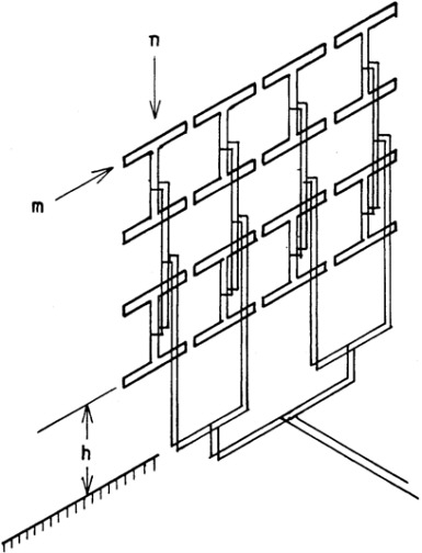
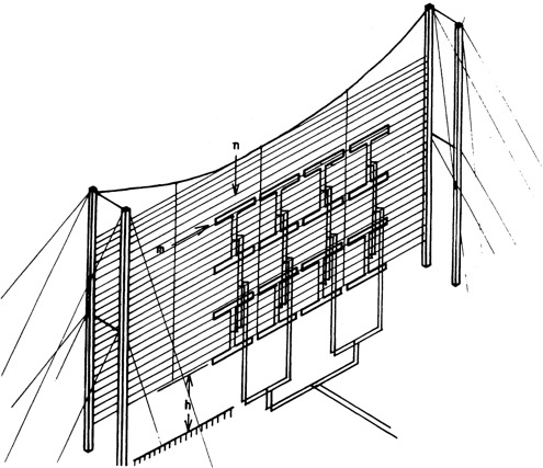
The antenna illustrated is an HR 4/4/h, i.e., four dipoles in each row and four dipoles in each stack. The number of elements employed in each row or stack will be selected to form the required azimuthal and elevation radiation characteristics.
The spacing of the folded-dipole radiating elements is about one quarter of a wavelength from the aperiodic reflecting screen and is usually half a wavelength between centers of the elements in each row and in each stack at the design frequency. The illustrations show an idealized feeder arrangement with all radiating elements being fed in phase. Maximum radiation will be in a plane normal to that of the elements. In the practical case the vertical feed lines will usually be constructed between the dipole radiators and the reflecting screen and include transforming and matching sections.
Switching, which may well be quite complicated, is usually introduced in the feeders at ground level to slew the beam azimuthally or to change the radiation characteristics in the elevation plane by modifying the phase relationships between the various feed points. Since switching feeder line lengths in the switchyard provides control of the phase of feed to each array element, these arrays may be thought of as “phased” or “scanned.”
Some typical examples of azimuth and elevation beamwidths based on the radiation patterns of horizontal dipole antennas over average ground are shown in Tables 2–1 and 2–2.
TABLE 2–2 Directional Characteristics of Typical Curtain Arrays (Elevation)
Distributed Arrays for the Voice of America
At the present time the VOA’s modernization program includes developing a number of new relay sites. While the time schedule for the development of these sites has required the utilization of curtain arrays of conventional design, the VOA has determined that future needs will require transmitting antennas with greater gain, steerability and bandwidth. Currently Technology for Communications, International (TCI) is developing two very large curtain arrays for the VOA that are steerable in azimuth and elevation. These arrays, which are high-band and low-band HR/12/6/0.5 antennas, are being installed at the VOA site in Delano, California to improve the VOA services.
All of the currently operating VOA antennas, including the experimental antenna at Delano, are driven by a single, high-power transmitter. Steering of these arrays requires high-power switchyards that are generally complex and costly. With this design approach it is difficult to maintain the highest possible gain while using the available flexibility of beam control. Also, only limited beam and gain configurations are possible. An alternative approach is to use a distributed antenna array in which a separate power amplifier is used to drive each row or column of radiating elements or even each radiating element, thus coupling a “distributed amplifier” with the distributed antenna array. Such arrays allow beam steering in azimuth and elevation to be accomplished electronically at low power levels, allow beamwidth changes, provide graceful degradation, permit on-line power-amplifier maintenance, and avoid losses and other problems of high-power switchyards. The following clear advantages of distributed arrays with electronic steering are realized:
-
Elimination of switchyard real estate, life cycle costs, and power loss
-
Higher gain for those cases where the entire distributed antenna can be used to produce gain instead of switching off part of a single transmitter antenna
-
More flexible beam control due to the ease of making rapid and fine beam-position changes, both in elevation and azimuth.
In costing a distributed amplifier, it is essential that the concept of a combination modulator and power supply of high efficiency be employed, using, for example, switched-mode techniques, together with multiple final amplifiers located as close as possible to the antenna elements they drive.* For valid cost comparisons of systems using distributed versus monolithic amplifiers it will be important to ensure that the multiple applications and the wide frequency range and steering capabilities of distributed-amplifier arrays be compared with those of an equivalent conventional antenna fed from a single transmitter. The comparison should include the cost of associated feeders and feeder and beam-control switching.
Horizontal Arrays
An alternative to the curtain antenna is the planar, two-dimensional array horizontally deployed. This array achieves elevation directivity by virtue of its projected vertical aperture normal to the take-off angle. For example, at a 10 degree (from horizontal) direction of radiation (the angle to which the beam is steered) the equivalent vertical height of the array is about 17 percent of the depth of the array on level ground. This concept makes a tradeoff of the curtain antenna with a distribution of antenna elements along the ground. (The extra cost of any additional ground space needed must be balanced against the life-cycle costs of the curtain towers.) The utilization of sloping terrain in such a concept can reduce the amount of real estate required as well as improve the low-elevation-angle performance of the array.
The relatively lower power required for each antenna element naturally leads to the concept of installing low-power transmitter units at each antenna element (a distributed amplifier-antenna array). The application of such concepts in the future may provide the VOA with increased performance and flexibility at lower system costs. The engineering evaluation of horizontal arrays depends on the specifics of a given application, inasmuch as tradeoffs are available between properties such as gain, scan angles, and site profiles.
Wideband Radiating Elements
VOA curtain arrays utilize broadband elements; array performance is limited both by element capabilities and by array effects. Wideband elements are essential to control the input impedance of the radiating elements over the two-to-one operating frequency range. By ensuring that the relatively complicated feeding system illustrated in much simplified form in Figure 2–1 remains reasonably matched over this range there is a greater probability that the power sharing between elements is maintained and that the specification for maximum allowable voltage standing wave ratio (VSWR) at the transmitter will not be exceeded. The maximum allowable VSWR at the transmitter is usually 2:1. The feeder and switching system introduce their own degradations, emphasizing the need for good impedance characteristics at the antenna over the frequency range. Broadband arrays have been used at higher frequencies in other applications, and some of this technology may be applicable to the VOA HF arrays. For example, it may be feasible to adapt ultra-high frequency (UHF), wideband-element technology to HF. The fundamental impedance and frequency characteristics of various types of radiating elements having the required bandwidths should be studied together with the modifications to those characteristics that occur when such elements are used in arrays. This effort should be oriented to computer modeling (e.g., moment methods) initially, as that allows faster and less expensive “experiments” and is adequate for most of the development process.
Antenna Measurements
The Committee considers it very important for the VOA to develop tests to measure the behavior of their antennas. Such tests fall into two categories: (1) comprehensive evaluation of radiation patterns, impedance, and gain on new types of antennas, such as those to be carried out on the antenna at Delano, and (2) the minimum practical tests to provide proof of performance of installed antennas at full power for acceptance testing.
In testing the Delano antenna it is particularly important that the gain be considered. The tests on this antenna should be such that the design process is validated. That is, measurements of absolute gain as a function of azimuth and elevation should be compared with the design values for various slew angles. In particular, phase and amplitude measurements of the current distributions should also be made and compared with the expected distributions. Pattern sidelobe levels provide a sensitive indication of errors in the current distribution. In the event that the measured patterns do not agree with the design values, patterns calculated from the measured current distributions should be compared with the measured patterns. This work should simplify and improve the design of future antennas, especially when slewed.
The acceptance testing of newly installed antennas must verify the design maximum gain, the azimuth of the maximum gain, design sidelobe level close to the main beam, and the back-to-front ratio. If the test results agree satisfactorily with the design values it can be concluded
that the amplitudes and phases of the currents in the radiators conform with the antenna design. If not, antenna readjustment may be indicated.
The Committee believes that such tests should be conducted using airborne receiving equipment to measure the radiation from the powered antenna. Airborne measurements have the unique advantage that they are the only method of determining the eventual radiation pattern. The radiation pattern of an HF antenna is formed as a result of reflection by the ground, and it may also be modified by currents flowing in the support structure. Data regarding the gain, accuracy of beam shape, and slew angle, as well as sidelobe level and the amplitude of the radiation both in the minima and to the rear of the antenna, should be available. None of these can be predicted from the amplitudes and phases of the current flowing in the radiating elements. If significant discrepancies between design and actual performance are found, such measurements could be an advantageous method of analysis. A calibrated, screened loop is considered to be a suitable, test antenna. The use of a helicopter with precise position finding would be the most suitable method of conducting these test measurements. A cheaper alternative might be to use a balloon as an airborne platform.
PROPAGATION AND DATA SOURCES
Propagation predictions form an essential tool in the management of an HF broadcasting system. The data from such predictions will be used to specify the types and operating frequency ranges of the antennas required to fulfill VOA objectives. Data will also be required for the operational scheduling of transmissions. In the first case the whole range of potential operating conditions needs to be reviewed and in the second case specific projections will be prepared for operations some months in advance.
The service available to listeners is then compared with that predicted. The reception data obtained can be used to correct anomalies in the predictions or differences between the predicted and actual conditions by making corrective changes in scheduling. Such changes will normally be effected in a time scale of days or weeks, as appropriate.
Improved corrective measures, to change the optimum grouping of frequency bands used or transmitting sites employed, can only be determined by having a diagnostic process which relates short-term observations to the long-term forecasts used to prepare schedules. The timing and extent of changes in scheduling to take account of mean daily and seasonal variation can then have a rational scientific basis. The listener reports used currently can only be retrospective and may not be representative of the whole reception area.
The Ionospheric Communications Analysis and Prediction Program (IONCAP) is a computer program already used by the VOA. It is considered to be the best available method despite having limitations in its input and output routines. The VOA should consider the possibility of improving the utility of the program by improving those routines, avoiding any changes of substance.
IONCAP, IONSUM, and VALSUM
IONSUM is a computer program using the output of the IONCAP prediction method to determine the most suitable frequency band and required antenna gain under specific averaged conditions. The acronym stands for IONCAP SUMmary.
The analysis procedure in IONSUM, based on the output of the IONCAP prediction method, was developed by the VOA to determine which single-frequency band will be most suitable under “averaged” conditions for a particular service from one transmitter site to a target reception area. The report of the predecessor committee (National Research Council, 1986) criticized IONSUM for excessive averaging and a restriction to the use of a single frequency band for a service to the whole of a reception area. The results from this averaging procedure need to be compared with predictions for a selected range of typical conditions using IONCAP, since typical conditions are not average. It will be necessary to consider the most suitable parameters to be used for optimization.
The Committee understands that the VOA recognizes the need to supplement the results from IONSUM with additional data from IONCAP regarding the extremes of ionospheric conditions (for example, at sunspot minimum and maximum) and their statistical distribution, and for individual hours rather than the time-block averages previously used in IONSUM. A newly created computer program known as VALSUM, now in use by VOA Engineering, does deal to some degree with earlier Committee concerns. VALSUM (acronym for VALidation SUMmary) takes results of IONSUM for a particular audience area, ionospheric conditions, and sunspot conditions and calculates required power gain, transmitting antenna gain, and beam illumination requirements for specified signal-to-noise ratios and fading margins. The Committee continues to caution, however, that if averaging is carried out at all, it should be done as late in the model-making process as possible. Effective, near-real-time, experimental verification of the IONCAP, IONSUM, and VALSUM routines cannot be carried out on highly averaged models.
Improved and Advanced Propagation Prediction Techniques
The investment in capital plant by the VOA should be accompanied by a parallel investment in improving applications of the available prediction methods to VOA operational requirements. Whatever propagation monitoring methods may be developed, the scheduling of operations, particularly for new or inaccessible audience areas, relies heavily on propagation predictions. An organized and methodical program should be established to improve operational performance by analysis of predictions and measurement results.
One potentially important input to verification of prediction methods is the measurement of vertical angle of arrival (AOA) signals in VOA reception zones and, when several propagation modes are present, their
relative times of arrival. These measurements together provide the basis for unambiguous identification of the propagation mode (or modes) involved. Possible methods for making such measurements include the following:
-
The measurement of relative radio-frequency (RF) phase, averaged over several fading cycles, of the received signal on two or more vertically spaced, omnidirectional antennas, which should give the AOA of the signal when only one mode is present or when one mode is much stronger than all the others combined
-
Frequency modulation (FM) chirp transmissions within the assigned bandwidth
-
The use of normal modulation as a quasi-pseudo-noise (PN) probe. The first two techniques can be used, with suitable processing, to obtain the relative delay and strength of multimode signals at the receiving site. However, they alone cannot provide unambiguous mode identification, because the absolute delay of the dominant mode is not obtained.
MONITORING
Reception-Zone Monitoring
Monitoring of the VOA’s HF signals in the intended audience area is highly desirable for determining the performance of the broadcasting system. To be effective, however, it requires the availability of accurate monitoring facilities, a process for analyzing the acquired data, and a method of comparing the monitoring results with the predicted performance. Comparisons need to be done relatively frequently and mechanisms must be in place to allow weekly corrections of the broadcasting system characteristics (e.g., power, antenna pointing, broadcasting site) if shown to be necessary. The current method of using mailed reports from volunteer listeners in the service area is not satisfactory from the viewpoints of objectivity, accuracy, timeliness, or effectiveness of the analysis and feedback mechanisms.
Sophisticated, quantitative measuring and reporting techniques are available. Without the analysis and feedback mechanisms, however, they may be no more effective than the present, subjective system. Thus, it is imperative that the VOA recognize this before implementing more sophisticated monitoring techniques and be prepared to invest in the appropriate resources for using the monitoring data.
Conventional signal strength monitors have relatively broad bandwidths, which makes them susceptible to noise and interference at frequencies near the frequency of the VOA transmission being monitored. To avoid this out-of-band contamination narrow-band monitoring of the RF carrier should be implemented to determine the signal strength of the desired signal alone. This information will constitute an important input to long-term predictions of ionospheric propagation.
A more useful technique supplements signal-strength measurements with signal-to-noise or signal-to-(noise-plus-interference) ratio data. Even
more useful is the measurement of received-signal quality. Typically, human monitors can assess signal quality with ease, but it is much more difficult to do this automatically. Automatic or machine assessment appears to be desirable for any large-scale monitoring system, because of the high cost and low availability of human observers as well as the need for automated reporting.
By way of illustration, some possible signal-monitoring techniques can be mentioned. Signal-to-(noise-plus-interference) ratio measurements can be added readily to signal-strength measurements by inclusion of a narrow-band filter centered on a frequency below the lowest modulation frequency, e.g., on the order of 40 Hz. The output of this filter will be a measure of the noise (or noise plus interference) present. After suitable processing the filter output can be combined with the signal-strength data to provide the required signal strength and signal-to-noise ratio information.
Two possible techniques for estimating signal quality automatically are suggested. The first technique involves phase-modulating the carrier of a double-sideband transmission with a long, psuedo-noise (PN) sequence which is known at the receiver. The received sequence is compared with the expected sequence and the error rate is determined. Although this method requires calibration for conversion to subjective signal quality, it has the advantage over the use of a coded subcarrier that the full transmitter power is available for the monitoring measurements.
The other method does not require additional modulation. Instead, it requires periodically, at known times, the transmission of a prerecorded voice announcement such as “This is the Voice of America.” At the monitoring receivers linear-predictive-coding (LPC) word-recognition programs in microcomputers determine the appropriate coefficients of the received message, compare them with the known coefficients of the transmitted message, and assess the differences between them. If the received signal is of high quality, the difference parameters will be small. As the quality of the received signal is degraded by noise or interference, the difference parameters increase. Thus, with calibration (which is probably easier to do than in the previous technique) the difference parameters can be used to assess the quality of reception. Word-recognition chips for use in microcomputers are readily available, and it is believed they could be adapted to the application suggested here. No doubt there are other techniques available. The important factors in selecting the technique to be used are (1) objective, automatic measurement without human involvement and (2) availability of output in abbreviated, numerical form that can be transmitted periodically to a central processing facility. These features are offered by both techniques described above.
Finally, it would be useful but not essential, that the monitoring equipment be emplaced at U.S. embassies, consulates, or United States Information Agency libraries or other sites located in the intended reception areas. Arrangements then must be made to send data back to the VOA in a timely manner. The service must be available for a few seconds to minutes every day to transmit the data back to the United States. It is also essential, as discussed above, that timely analysis of the data be
performed. Appropriate monitoring equipment should be deployed temporarily at sites separated initially by about 500 km, in order to estimate the area within which monitoring results at one site are representative of those throughout the area.
Out-of-Country Monitoring of Voice of America Transmissions
In addition to signal monitoring capability within each audience area, the VOA should consider some form of external monitoring. This is an alternative approach to providing information on the spatial footprint of a particular transmission as well as on the ionospheric transmission path through which the transmission reaches its destination. Monitoring of this type can be quite powerful since it provides near real-time information on both the spatial extent of the footprint and the azimuth and elevation angles for optimum transmission. This information can be used to increase the signal strength in the audience area as well as to improve VOA ionospheric prediction models. The disadvantage of external monitoring is that it cannot be used to determine the noise or interference levels within the audience area. Nor will external monitoring fully substitute for feedback from the resident population, which it is VOA’s real mission to reach. Without this feedback it is not possible to say whether a doubling of power or antenna gain will add even one more listener.
External monitoring is based on the fact that some of the energy in a transmission is, in addition to being reflected onwards, backscattered toward the transmitting site at each ground hop. In general, the backscattered energy returns to the transmitter along the same propagation path. The returning signal can be analyzed to derive propagation delay as well as horizontal and vertical angles of arrival. It would also be possible to derive appreciable information on the propagation path as well as the spatial extent of the footprint at each ground hop. The approach is most useful for transmissions requiring a single hop. At single-hop ranges there is generally significant power in the backscatter returns as well as a small number of possible paths that can bring the transmission to any given range.
The source of the backscatter at any ground hop is roughness in the terrain. Cities in the service area will produce stronger backscatter returns than the surrounding countryside, mountains will scatter more than grasslands, and disturbed water surfaces will scatter more than a calm lake. Consequently, the backscatter image will display appreciable surface variability due to cities, mountains, and other rough terrain features. This variability may be used to calibrate the propagation at any particular time. For each feature in the image as well as for the image as a whole it is possible to determine the range to the feature, its bearing, and the takeoff angle of the transmitted energy reaching that feature. By monitoring the bearing and takeoff angles that are required to bring a transmission into a particular service area, one can confirm or improve the predictions of VOA propagation models. Adjustments in the bearing and takeoff angle of VOA transmitting antennas will improve system performance.
Ideally, an external monitoring facility should be set up within each country for which a new VOA relay facility is being developed. From this site the monitoring facility could monitor backscatter from each of the listener areas serviced by that relay facility. The monitoring facility could be designed to utilize the transmissions from the local VOA relay facility or it could utilize its own signal source. In the former case, some additional modulation would be required on the VOA signal, or some sophisticated pattern recognition software or hardware would be required at the monitoring site in order to provide range information on the backscatter source. In the latter case, the monitoring site would operate independently of the relay site at frequencies near, but not at, the frequencies transmitted by the relay site. In the event that the monitoring station were to utilize its own transmissions, an average power capability of 1 to 10 kW would probably be required.
Any of a variety of designs could be incorporated into a monitoring station. One example is given in the report to the VOA by SRI International (Carpenter et al., 1985). The choice of design should be dependent on the ability of the monitoring system to discern the range, bearing, and elevation-angle footprints of the backscatter returns from each of the ground hops.
RECOMMENDATIONS
The preceeding material leads the Committee to the recommendations that follow.
-
The VOA should initiate a program to investigate the applicability of distributed amplifier-antenna arrays to VOA transmission requirements, considering the following items:
-
Perform computer analyses of the relative merits in beam formation and slewing of individually-driven radiating elements or groups of elements versus driving the array from a single transmitter.
-
Evaluate the relative cost of large, vertical, curtain arrays with individually powered radiating elements or groups of elements on the one hand and with the entire array driven by a single transmitter on the other.
-
Initiate development and procurement of a distributed-amplifier transmitter including power supply. Important objectives are the achievement of high efficiency and low cost.
-
Design and construct experimental, distributed-array systems of modest transmission capability at some U.S. site.
-
Evaluate the operational performance of this experimental configuration with regard to fulfilling VOA requirements and in comparison with existing operational requirements.
-
-
The VOA should plan and start a computer modeling effort on wideband array elements, with the objective of evaluating elements developed for higher frequencies for use in HF curtain arrays.
-
The VOA should study the horizontal-array concept for possible future applications. The study program should include the following items as appropriate:
-
Theoretical studies of array slew behavior and element driving-impedance behavior, including mutual coupling as a function of array layout and terrain slope
-
Experimental tests of the theoretical results using inexpensive, low-power transmitters and antennas
-
Cost tradeoff studies, based on the above results, that compare life-cycle costs of vertical curtain arrays and horizontal arrays.
-
The VOA should perform an advanced-technology measurement study to develop techniques for verifying (or improving) the theory used in the design of their HF antenna systems, and for acceptance testing of newly installed antennas.
-
The VOA should take the following steps to make use of information available from backscatter observations:
-
Develop a set of requirements for an operational backscatter monitoring system.
-
Construct a prototype system, preferably at a readily available U.S. site such as Delano, California, where the VOA has recently installed as new, high-performance antenna.
-
Implement a test program to evaluate VOA performance enhancements that may be achieved through the utilization of backscatter monitoring data.
-
Develop methods for measuring vertical angle of arrival of HF signals from distant transmitters.
-
-
The VOA should undertake to develop the following capabilities for using the information available from signal-strength observations:
-
Objective, automatic methods for determining the strength of its signals, signal-to-(noise-plus-interference) ratios, and their correlation with the quality of its signals in intended audience areas
-
Techniques for processing the measurements so that they can be transmitted regularly from the audience area to a VOA processing facility in a timely manner with little or no human intervention
-
Operational methods for processing and analyzing the resulting data so that they can be used for operational decisions and as input data for evaluation and improvement of propagation-prediction techniques.
-
Without the operational use called for in the last point any attempt at improved monitoring will be futile. Reception-zone monitoring to evaluate these methods and techniques could be undertaken at Caribbean sites in conjunction with the new antenna facility at Delano, California.
REFERENCES
Carpenter, G.B., R.P.Basler, E.J.Brackman, G.N.Hagn, J.F.McCarty, G.Smith, and H.E.Stuler. 1985. VOA Worldwide Monitoring Analysis: Task 2—Geographic Offset Monitoring. Final Report. Menlo Park, California: SRI International.
International Telecommunication Union. 1984. Radio Regulations. Geneva.
National Research Council. 1986. Modern Audio Broadcasting for the Voice of America 1986–2001. Washington: National Academy Press.


