
6
Future Warrior Design Concepts
Chapter 5 explained that the energy efficiency of circuits has improved at least fivefold since 1997. In the same period, system designers added new functionality to dismounted soldier applications with the expectation that existing power sources, or those being developed, would prove sufficient. The simple fact, however, is that the laws of physics and chemistry preclude the development of wearable power sources with the needed combination of energy, weight, and size that will not affect the soldier’s agility. It is therefore imperative that the Army devote R&D effort to reducing power demand as it continues to develop and improve its power sources.
This chapter discusses design concepts for the Land Warrior (LW) systems to be borne by future warriors in the far term (2020 and beyond) and lays out a grand challenge for the Army to reduce overall power demand by an order of magnitude, from the 20-W regime now contemplated to 2 W or less. By adopting state-of-the-art (SOA) commercial design practices and incorporating power management technologies, peak power demand on energy sources can be reduced, increasing the combat effectiveness of individual soldiers and extending the duration of their missions. Aggressive power system designs tailored to the applications could take into account soldier modes of interaction and reduce power requirements for computation and communications, without affecting the effectiveness of the ensemble.
LOW-POWER SOLDIER SYSTEM
The numerous advantages of reducing power demand to 2 W from 20 W are obvious and undeniable. The committee believes that such a goal is attainable and should motivate the Army to expand its role in developing the soldier system. Perhaps most importantly, a 2-W system would not be dependent on developing Army-unique power systems. To illustrate, the committee reviewed and assessed power source technologies for a hypothetical regime that would include electronics applications demanding 2-W average and 5-W peak powers.
2-W Average with 5-W Peak
The total system mass of three batteries and two fuel cells that produce 2 W average power is shown for 24- and 72-hour missions in Figure 6-1. The battery technologies chosen for comparison are SOA primary Li/MnO2 (280 Wh/ kg, as extrapolated from Table D-1), secondary Li ion (170 Wh/kg, see Table D-2), and Li/(CF)x (820 Wh/kg, extrapolated from Table D-1). The specific energies used for Li/MnO2, Li ion, and Li/(CF)x are reasonable projections for these chemistries but do not include a penalty for packaging multiple cells. For example, currently packaged LW batteries have the following characteristics: 195 Wh/kg for the 175-Wh LM11 Li/MnO2 primary battery and 145 Wh/kg for the 135-Wh LI9 Li ion secondary battery (Brower, 2003). The points for Li(CF)x are based on a much larger cell, which might not yield this performance in the sizes and discharge rates required for these missions, even though improvements in the system are likely.
Data for other battery chemistries that are discussed in this chapter would fall within the range bounded by the Li ion and Li/(CF)x data. The only other technology discussed is the passive direct methanol fuel cell, which is at an advanced stage of development. The points are derived from data produced from fully packaged systems including fuel.
Several battery technologies meet the 2-W regime power requirement with a mass of less than 1 kg. For both 24- and 72-hr missions, it is clear that SOA primary and secondary batteries are the best choice and, with further improvement, might be the only choice. Given additional development time, passive direct methanol fuel cells (DMFCs) might yield performance comparable to that of some of the batteries. A possible basis for pursuing the DMFC rather than batteries would be logistics, not performance. Any
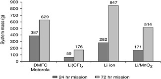
FIGURE 6-1 System mass of five energy sources producing 2 W average power for 24- and 72-hr missions.
battery with a specific energy exceeding 300 Wh/kg would exceed the performance of both DMFC and Li/MnO2 and would be a good candidate.
As with the 20-W regime, if the same battery were used for average and peak power, the degree to which the peak power demand would degrade the specific energy would depend on the duty cycle. In the 2-W regime, a capacitor could be used for the 5-W peak if the pulse width is sufficiently short. An appropriately sized Li ion battery or a capacitor would most likely provide the 5-W peak power for the passive DMFC option, which would be optimized for the average power load.
At such low powers, advances in thermoelectric materials make them viable candidates for energy conversion systems. Thin film materials could enable very lightweight thermoelectric modules. Furthermore, they could be used in conjunction with catalytic combustors employing jet propellant 8 (JP-8) fuel, which has twice the energy content of methanol. However, even extremely optimistic energy efficiencies for a thermoelectric system are less than the 20 percent efficiency of a passive DMFC system. Other factors, such as system simplicity or size and weight, could make the thermoelectric option viable for some applications.
At the 2-W power level it is also possible that energy harvesting technologies could affect the overall weight and volume of the power source system. As with a DMFC system, the total energy harvesting system would have to perform significantly better than the battery it would replace. The total system weight for a given power produced and the often-intermittent nature of energy harvesting technology must be taken into account in any trade-off analysis. The significant benefit of using energy harvesting is the inexhaustible supply. This would free future warriors from concern about having no backup for dead batteries.
SYSTEM-LEVEL APPROACH
A 2-W soldier system would require a system-level approach to design that would consider both the energy consumers (sinks) and the power sources. Many techniques can be used to improve the energy-efficiency of a system, from the network level down to the physical level of the battery. At the network level, routing methods tailored to the power demanded by the network subsystem can improve power levels by 15 percent on average and reduce latency by 75 percent relative to methods that consider only the transmitted power.
At the boundary between the network and the processor levels, a computation can be performed locally or remotely depending on the relative performance of the local and remote system, the transmission bandwidth and power demand, and the network congestion. The largest power demand in a mobile computing system is for communication and computation. Techniques for reducing the energy usage in these areas include energy-aware network routing, balancing local and remote processing, and changing the central processing unit (CPU) speed dynamically.
Techniques for communication and computation cannot be studied in isolation: one technique for reducing communication energy usage is to perform more local processing, but this increases the amount of computation energy. Thus in the case of local vs. remote processing, the communication and computation subsystems must be considered together. For the system studied by Martin et al. (2003), energy can be conserved by remote processing any task that requires more than 1.4 milliseconds of processor time per kilobyte transferred. At the processor level, the main memory bandwidth has a significant effect on the relationship between performance and CPU frequency, which in turn determines the energy savings of dynamic CPU speed-setting.
The power sources must be considered as well. In particular, the energy delivered by a battery depends on the rate at which it is consumed. Consequently, reducing peak power can increase the battery life of the system by increasing the energy available. Large peak power has been shown to reduce the energy delivered by a battery by up to 40 percent. Electrochemical capacitors can be used to mitigate peak demands and improve battery life by up to 10 percent. The use of energy-aware operating system schedulers can reclaim even more of the battery capacity (Martin et al., 2003).
Table 6-1 summarizes mitigation techniques in key areas to improve energy efficiency. It lists improvements that could be realized by using a system approach toward mitigating energy issues associated with just the communications and computation functions of the Land Warrior.
In summary, greedy approaches to energy efficiency that consider subsystems in isolation will not be optimal. A system-level approach, one that considers energy consumers and power sources, is the proper method for examining energy efficiency in battery-powered computing systems.
POWER MANAGEMENT AND DISTRIBUTION
Land Warrior systems can be subdivided into four functional areas: displays, computing, sensors, and communications. Each functional area requires one or more power sources for electronics such as were listed in Table 5-1.
Distributed vs. Centralized
There are two basic approaches to power distribution: centralized and distributed. In centralized power distribution there is a central power source that is distributed by wires to the various power sinks. The centralized source may generate bulk power to distributed power regulators, which smooth out spikes and maintain voltage at the specified level for the various sinks (or for small, local, rechargeable batteries—this would allow various elements of the system to operate briefly if the centralized power source went down). If the system is small enough and the sinks have similar voltage requirements, the regulation may also be done at the centralized source. Since the energy density of batteries usually increases with battery size (owing to less packaging per unit volume), the centralized power option should result in higher energy density than the distributed power option and a lighter weight battery for the soldier.
The centralized power option should allow one to reduce the types of power sources needed. In theory, by coupling with DC-DC converters, it should be possible to use only one type of power source, with a secondary one of similar type as backup. Owing to the inefficiencies of DC-DC converters, there is a penalty of about 10 percent, but energy can be saved in the sink by keeping the voltage constant at the lowest possible level, particularly where the battery voltage changes greatly during discharge.
Additionally, central power will require that equipment be tethered to the central power source. The tethered equipment that would probably cause the most practical problems for the soldier is the weapon subsystem and the helmetmounted heads-up display (HUD). The proposed OFW weapon subsystem has 14 components that draw power (Acharya, 2003). However, because a tethered weapon is prone to becoming entangled with protruding objects, its reliability should be studied in the field before implementation. Ultimately, the need to exchange an enormous amount of data via wires will dictate that the four functional areas of the OFW system be tethered together through wires. Consequently, one should be able to distribute the power from a central source through these tethered wires also. In other words, the unavailability of a wireless body LAN necessitates the use of tethered wires, which, in turn, dictates the centralized power approach. Advantages and disadvantages are summarized in Table 6-2.
In distributed power generation, the generation source, power regulator, and sinks are distributed around the body. There is no need for encumbering, tethering wires to connect
TABLE 6-1 Techniques for Mitigating Energy Issues in Key Land Warrior System Components and Improvements That Could Be Realized
TABLE 6-2 Advantages and Disadvantages of Centralized and Distributed Power Distribution for Use by the Dismounted Soldier
|
|
Centralized Power |
Distributed Power |
|
Description |
Centralized power generation, with either centralized power regulation or individualized power regulation associated with each sink. |
Individualized power generation and power regulation associated with each sink. |
|
Pros |
Power generation more efficient at less total weight. Easier power generation maintenance. Logistics simplified owing to single power source type—no need for multiple different battery types. |
Increased flexibility by having power associated directly to sinks. Fewer I2R losses owing to shorter wire lengths. Survivability/ reliability of system enhanced—equipment still functional if central power source lost. |
|
Cons |
Extra weight, due to wires for power distribution, and decrease in mobility, due to tethering sinks to the centralized power source (consideration moot if data must be transmitted from gun sight or helmet-mounted heads-up display with wires/cables anyway). Lacks power source redundancy/reliability gained with distributed systems. |
Extra overhead weight associated with multiple power generation sites. Additional battery management overhead by soldier. May still require on-soldier battery recharging that could act as central power source. |
the systems together (except, perhaps, to distribute data via wire for security). The obvious disadvantage of the distributed power option is that the dismounted soldier would have to carry varying quantities of different batteries, possibly increasing the weight carried for extended operations.
An alternative distributed battery scheme might utilize rechargeable distributed batteries that could be recharged on the soldier within a converter re-charger pouch. Hence the soldier would need (at a minimum) twice the number of secondary batteries as pieces of gear. This would require that each piece of gear be redesigned to accommodate a new battery geometry, which is harder than wiring an existing battery compartment to be powered via a cable, as is the case for a centralized power scheme.
Another consideration raised by the numerous types of batteries needed for the distributed power option is the likelihood that the soldier would need to replace batteries during operation, which could endanger his or her life in the midst of a firefight. There is also added weight for such things as battery containers and basic components for power regulation. A possible (but somewhat impractical) remedy would be to standardize the voltage range of batteries for all the energy-consuming devices so that only one type of battery is needed. However, this would increase the power budget of the OFW system.
The initial OFW concept combines the advantages and disadvantages of both centralized and decentralized power distribution. Many of the sensors have dedicated power sources, yet the sensors are tethered together using data cables. (Note that current USB hubs can routinely source 2.5 to 4 W per node, so that both limited power and data can be provided in a common connector/communications format. This protocol—as well as the 1394 FireWire protocol—is being studied for use by OFW). In addition, the different sensors may have different battery types, compounding logistics for the individual soldier and for supplying field units. For example, if there are 10 separate battery sources, each sized to the duration of a mission, a soldier might have to replace 10 batteries, possibly on 10 different occasions.
In summary, in the near term, the need to exchange an enormous amount of data dictates the use of tethered wires, thus favoring centralized power distribution and management. In the long term, when the wireless body LAN is available, it will enable more robust distributed power distribution. However, for the total OFW system power estimated, the power sources are still too heavy to allow for the distributed power option. More effort should also be devoted to simplifying the components of the weapon subsystem in order to reduce complexity and, consequently, the weight budget of the power sources needed.
Realistically, advanced power sources and aggressive power management will be needed to reduce the weight of the power sources, thus enabling the more robust distributed power option. As discussed in the following section, using power management in the design stage could reduce the total OFW system power to less than 2 W and enable deployment of commercial off-the-shelf power sources.
Power Management Design Approaches
This section discusses approaches toward reducing power demand by including power management concepts in the system design of LW systems. The most efficient and straightforward way to obtain energy savings is to power down any circuitry that is not being actively used. The power-down approach can be applied directly, or it can also form the basis for indirect techniques, such as in smart dust and asynchronous designs. Although soldier requirements
TABLE 6-3 Subsystems in Objective Force Warrior with Estimated Duty Cycle of 0.98 W
are volatile, aggressive power-down—coupled with low standby power demand—can be directly applied to the OFW design.
One method of reducing the power for LW would be to utilize power-down technology for devices with heavy duty cycles. As depicted in Table 6-3, a number of OFW subsystems are almost continuously drawing peak power. The average power for these subsystems (7.986 W) is almost half (0.466) of the total system average power (17.149 W).
Similar heavily utilized subsystems also appear in Stryker. Table 6-4 shows that the average power for these subsystems (13.1 W) is more than two-thirds (0.672) of the total system average power (19.5 W). Two of the subsystems, the computer and the wireless local area network (WLAN) card, could use more aggressive power management protocols—for example, the WLAN cards can use a beacon technique wherein they awaken for 10 milliseconds every second. If any card has information to transmit, it would send a keep-awake message during the beacon period. The WLAN cards stay active until all the information has been exchanged. In times of little information exchange, the WLAN subsystem would have a duty cycle approaching 0.01. Likewise, the computer system and voice communications could be activated only when required. An onset-of-speech circuit, coupled with a 10-millisecond circular audio buffer, could wake up the other subsystems when there was audio activity. The buffer ensures that the initial part of the speech utterance is not clipped.
In the present OFW design concept, almost half of the average power demand comes from components with duty cycles of over 90 percent (see Tables 6-3 and 6-4). This is so in spite of the fact that functions such as voice communication could operate at duty cycles of less than 10 percent and network components that are commercial devices (such as the network hubs) could be designed to be actively powered off instead of simply left on all the time. An additional problem is that even when many of the components are put into standby, they continue to need significant power. Without design change, this problem will probably become worse, since the digital circuitry itself will have leakage currents that can only be controlled through intentional design strategies.
To accurately determine power source requirements, it is necessary to measure the actual duty cycles of the various components used in soldier operations. This measurement can be used to model the active, peak, and standby power of all the components, so that each power sink can be simulated. These models can be used in a full simulation of the dynamic operation that works with a source simulator (e.g., the White source simulator). This full simulation of OFW power sources and sinks should be used to make the investment decisions, which will have the most impact on developing hardware that substantially reduces power demand.
These and other simulations to resolve soldier power issues will require high-fidelity models and high-performance
TABLE 6-4 Subsystems in Stryker with Average/Peak Active Power Ration Greater Than 0.50 W
computer capabilities. The Army should therefore consider taking advantage of the high-performance computing (HPC) assets at the two DOD major shared resource centers—the Army Research Laboratory (ARL) and the Engineer Research and Development Center (ERDC).
Smart Dust
Smart dust sensor networks show how savings can be realized using a power-down strategy and high levels of integration with system-on-a-chip (SoC) technology. Such networks are estimated to have lifetimes of more than 3 years from two AA batteries. This is accomplished using conventional hardware and a microprocessor that has an energy efficiency of 1.6 MIPS/mW, which is a typical value for software processors. The energy efficiency of the approach is gained almost entirely from the aggressive power-down strategy and protocols, which require the device to be active for only 1 or 2 percent of the time. This strategy is coupled with sleep modes, which need only microwatts of power to achieve the long unattended lifetime required for that application.
“Smart dust” is a term that was coined by Professor Kris Pister of Berkeley under a DARPA program to develop MEMS-based sensors and electronics, but this term is now also used broadly to describe sensing and transmission systems on a chip. The “dust” part of the program has not been realized, but the development of autonomous sensors and their role in networked systems may have a significant impact on the military. Early prototypes have shown potential for multiple years of operation, assuming that the data will be transmitted over relatively short ranges. Such short communication lengths assume that the devices are dispersed in aggregates and then use multihop transmission to transmit data to a base station with more power for longer-range transmission to a military installation or soldier. The power needed to transmit increases exponentially with the transmission distance, which is dramatically reduced when a multihop strategy is employed. This also is an important energy conserving concept.
The smart dust concept becomes impractical for truly dust-sized or micron-sized devices. Presently, these devices are realistic only if they are several cubic centimeters in size with relatively limited electronic sensing and transmitting functions. A concept even more challenging envisions mite-sized devices that would have computing capabilities for intelligent sensing plus the ability to move (crawl, fly, and/ or climb)—such devices have been termed “cognitive arthropods.” The “bugs” would require current on the order of 40 mA not only for transmission but also for mobility and would occupy a total space of 2-3 cubic centimeters, with 1 centimeter allocated for the energy source.
The proceedings of a workshop on cognitive arthropods (Main, 2003) suggested that approximately 30,000 Wh/L would be needed for these smart bugs to carry out the stated military goals. Batteries and fuel cells obviously cannot deliver this quantity of energy, leaving micronuclear or energy-harvesting devices as the only power source option. Sensors can be employed today for autonomous networks with limited sensing and transmission capabilities, but devices that are dust-sized are still well in the future and will require innovations in computing and cognitive capabilities as well as in energy sources. The direction of smart dust development is integration of the sensing, computing and communication functions into an SoC. This lends support to the committee recommendation to use SoC in developing soldier electronics and illustrates the importance of an aggressive power-down strategy to conserve energy.
Very Low Power Asynchronous Circuitry
Another way to optimize low-energy operation uses essentially the same strategy at the circuit level. Unlike clocked circuits, asynchronous circuits only turn on when notified that new data are available. This approach is still at the research stage, but it might be used for application-specific integrated circuit (ASIC) and system-on-a-chip (SoC) designs once it is fully developed.
Private companies have worked on asynchronous systems over the past three decades with varying results, but there is now a strong resurgence of interest because of the increasing power drain and power density in high-performance chips. Asynchronous system technology serves to reduce power drain by dealing with timing problems in circuits using sub-100-nanometer processes. The circuits operate only when a signal activates the circuit when new data are available.
The number of commercial applications requiring low-power design has increased dramatically, and there is growing interest in asynchronous systems for this reason as well. Large companies worldwide are now either using or exploring the use of asynchronous circuits for full or partially unclocked chips in order to significantly reduce the power wasted by having every switch receive clocking pulses whether it is involved in the calculation or not. The companies include Philips, Intel, Sun Microsystems, and many smaller companies. New designs have evolved that minimize the amount of handshaking required to synchronize the circuit elements in the absence of a common clocking impulse.
The use of asynchronous designs has recently been stimulated by Philips through its offer to share its tools, techniques, and design expertise and software with other companies. This is important, because the lack of design tools has been a major impediment to integrating advanced and sophisticated techniques into designs that could be used in soldier systems.
Asynchronous design especially makes sense for very large digital circuits with fast clocks, when the energy cost of maintaining global synchronization of the clocking net-
work becomes prohibitive. However, this is a design space that currently has very little to do with soldier power problems. For digital signal processing, which is the dominant computation in the soldier system, asynchronous design is not so helpful, since there are real-time (synchronous) processing constraints that must be met. Also, the energy-efficient architectures for this kind of processing do not require high clock rates, so the energy cost of maintaining global synchronization is low. Finally, and most important, since the Army and its contractors do not even take advantage of conventional design strategies for integrated circuit digital design to save power, it would not make much sense to embark on a new strategy that is clearly at the early research level.
The best way to deal with the leakage issue is to work not with the fastest low-threshold (high-leakage) devices but with the low-power libraries, which means slower logic but lower leakage. Some designs (e.g., those for cell phones) use what are called foot (or sleep) switches, which put a switch in the supply lines to turn off the supplies during power-down periods. So the answer is not to go to the fastest clock rates but to use slower parallel architectures to do high-performance digital signal processing chores and avoid the power losses inherent to the clocking networks.
IMPACT OF SOLDIER INTERACTION ON ENERGY CONSUMPTION
Software designers have a rich variety of interface types to select from. Table 6-5 lists interface types in ascending
TABLE 6-5 Computational Requirements to Support Different Forms of User Interfaces
order of required computing performance. As can be seen from the table, different interfaces require computing performance levels that differ by orders of magnitude.
The type of data to be exchanged must also be selected. Table 6-6 depicts four basic data types that can be used for transmitting a report. The simplest would be filling in a form by selecting values from a menu for each question in the form. To illustrate, assume that 100 different questions must be answered by selecting a single word from a menu for each question.
-
Text. Assuming one word per question, an average of five characters per word, and eight bits per character, 4,000 bits of information would be generated.
TABLE 6-6 Sample Attributes of User Interfaces
-
Audio. Assuming that the user files an audio report that requires 60 seconds to complete, sampling and encoding for audio require 2.4 kilobits per second.
-
Still picture. Assuming a video graphics array (VGA) picture composed of 640 × 480 pixels with 16 levels of gray scale for black and white, the result is 1.23 million bits of data (e.g., 640 × 480 × 4). A color picture with 8 bits for each of the primary colors requires six times more data, or 7.38 million bits.
-
Video. The report could also be filled with video clips. Assuming the same VGA quality as the still picture at 30 frames per second, a 10-second video clip requires 300 times more data than the corresponding black and white or color picture. The software designer can reduce the number of bits that need to be transmitted by applying compression algorithms. As shown in Table 6-6, a video frame can be compressed by a factor of 30 at the expense of eight million operations.
Once the user interface type and data type have been selected, the software designer can estimate the amount of energy required to support the interface and to transmit the data type. Once the total energy is known, the amount of battery weight needed for operation of the designed interface can be calculated.
Interface Design Example
Consider the design of the input interface using variations of the parameters shown in Table 6-6. Table 6-7 summarizes the battery-weight computation for a simple mechanical physical interface operating a textual software interface transmitting text, sound, still photographs, and color video clips. To provide contrast, an audio speech recognition interface for transmitting text and color video is also included.
For the textual input it assumed that one word can be selected from a menu every three seconds, yielding 300 seconds of operation for 100 words or 300 million operations per second (MOPS). It is assumed that the same report could be given with 60 seconds of audio clip, which requires 60 seconds of user interface usage. For both the still and the video it is assumed that the visual inputs can be captured with 30 seconds of interface usage.
The energy for computing can be estimated by dividing the total energy of the computing system by the million instructions per second (MIPS) performance rating from standard performance benchmarks. For the purposes of Table 6-7 we have assumed 0.1 MIPS/mW, which is typical of present day microprocessors (see Figure 5-1). In order to convert this energy into watt-hours we have to divide the energy per MIPS by 3,600, the number of seconds in an hour. Thus in Table 6-7 the energy for the textual interface with 100 words of text is
(300 MOP)(10−4 W/MIPS)/(3,600 sec/hr) = 8.33 × 10⁻⁴ Wh
The energy to transmit data is the product of the number of bits to transmit times the energy per bit measured in watt-hours per bit. For this example we will assume a 1.5-GHz frequency, which would require 3.4 × 10⁻⁹ Wh to transmit a bit 1 kilometer in an outdoor environment with a moderate number of trees. Thus the amount of energy to send 4,000 bits is
(4 × 103 bits)(3.4 × 10⁻⁹ Wh/bit) = 1.36 × 10⁻⁵ Wh
Finally, the battery weight can be determined by dividing the total energy by the specific power of the battery measured in watt-hours per kilogram. Assuming 200 Wh/kg battery technology, the textual interface using 100 words of text as a data type would require
TABLE 6-7 Interactions Between User Interface and Data Types with Respect to Energy Required for Computing and Data Transmission
(8.33 × 10⁻⁴ + 1.36 × 10⁻⁵)/200 = 4.24 × 10⁻⁶ kg
As can be seen from Table 6-7, the type of user interface and the type of data selected can have a dramatic impact on the energy consumption and consequent weight of the system. For example, a 10-second color video clip without compression would require 37.5 g of battery weight. Table 6-7 shows that the user interface design can affect energy consumption and battery weight by four orders of magnitude.
DESIGN GUIDELINES FOR WEARABILITY
Society has historically evolved its tools and products into more portable, mobile, and wearable form factors. Wearable implies the use of the human body as a support environment for the object. Clocks, radios, and telephones are examples of this trend. Computers are undergoing a similar evolution. Simply shrinking computing tools from the desktop paradigm to a more portable scale does not take advantage of a whole new context of use. While it is possible to miniaturize keyboards, human evolution has not kept pace by shrinking our fingers. There are minimal footprints beyond which objects become difficult to manipulate. The human anatomy introduces minimal and maximal dimensions that define the shape of wearable objects. The mobile context also defines dynamic interactions. Attempting to position a pointer on an icon while moving can be tedious and frustrating.
Wearability is defined as the interaction between the human body and the wearable object. Dynamic wearability includes the human body in motion. Design for wearability considers the physical shape of objects and their active relationship with the human form. Gemperle et al. (1998) explored history and cultures, including topics such as clothing, costumes, protective wearables, and carried devices. They studied physiology and biomechanics, movements of modern dancers and athletes. Also drawing upon their experience with over two dozen generations of wearable computers representing over a 100 person years of research, the results were codified into guidelines for designing wearable systems. These results are summarized in Table 6-8, which could be used to guide system designers of future warrior systems.
TABLE 6-8 Design-for-Wearability Attributes for Computers
|
Attribute Relating to: |
Comment |
|
Placement |
Identify where the computer should be placed on the body. Issues include identifying areas of similar size across a population, areas of low movement/flexibility, and large surface areas. |
|
Humanistic form language |
The form of the object should work with the dynamic human form to ensure a comfortable fit. Principles include inside surface being concave to fit body, outside surface being convex to deflect objects, tapering sides to stabilize form on body, and radiusing edges and corners to provide soft form. |
|
Human movement |
Many elements make up a single human movement: mechanics of joints, shifting of flesh, and flexing and extending of muscles and tendons beneath the skin. Allowing for freedom of movement can be accomplished in one of two ways: by designing around the more active areas of the joints or by creating spaces on the wearable form into which the body can move. |
|
Human perception of size |
The brain perceives an aura around the body. Forms should stay within the wearer’s intimate space, so that perceptually they become a part of the body. (The intimate space is between 0 and 5 inches off the body and varies with position on the body.) |
|
Size variations |
Wearables must be designed to fit many types of users. Allowing for size variations is achieved in two ways: (1) use of static anthropometric data, which detail point-to-point distances on different-sized bodies, and (2) consideration of human muscle and fat growth in three dimensions using solid rigid areas coupled with flexible areas. |
|
Attachment |
Comfortable attachment of a form can be created by wrapping the form around the body, rather than using single-point fastening systems such as clips or shoulder straps. |
|
Contents |
The system must have sufficient volume to house electronics, batteries, and so on, which in turn constrains the outer form. |
|
Weight |
The weight of a wearable should not hinder the body’s movement or balance. The bulk of the wearable object weight should be close to the center of gravity of the human body, minimizing the weight that spreads to the extremities. |
|
Accessibility |
Before purchasing a wearable system, one should walk and move with the wearable object to test its comfort and accessibility. |
|
Interaction |
Passive and active sensory interaction with the wearable should be simple and intuitive. |
|
Thermal |
The body needs to breathe and is very sensitive to products that create, focus, or trap heat. |
|
Aesthetics |
Culture and context will dictate shapes, materials, textures, and colors that perceptually fit users and their environment. |
|
SOURCES: Gemperle et al., 1998; and Siewiorek, 2002. |
|
Long-term use of the wearable computers and Land Warrior ensembles may have unknown physiological effects on the human body. For soldiers, the combination of functions may also have unknown effects on combat effectiveness and performance. As such systems are used for longer periods of time, it will be important to test their effect on the wearer’s body.
FINDINGS
Considering all levels in the system, power management of general-purpose computing functions can decrease power requirements by a factor of 2. Reducing peak power demand is especially important, because it increases the life of the energy source. Designing a system using aggressive techniques tailored to the application and to the user modes of interaction can reduce power requirements for computation and communication by several orders of magnitude. In turn, this will reduce weight required for the power sources and enable the system to utilize distributed versus centralized sources.
There are numerous ways to manage and reduce power using energy-efficient design techniques. R&D investment will be needed to enable the Army to evaluate the use of conventional architectures and logic and determine relative advantages of different architectures and circuits to employ for the analog and digital processing in soldier systems as well as to determine the appropriate levels of integration. Modern SoC technology must be demonstrated in soldier systems before its potential can be realized, and such technology will be essential to meet the grand challenge of a 2-W soldier system for future warriors.


