
3
Delivery and Disassembly Operations
ON-SITE MUNITION TRANSPORTATION
The Blue Grass Chemical Agent Destruction Pilot Plant (BGCAPP) design and operations for the delivery and disassembly of chemical munitions are similar to those used in baseline incineration system facilities but include evolutionary modifications that take advantage of lessons learned from operating baseline facilities. Other modifications include new machines and technology to accommodate the use of caustic hydrolysis for neutralization of agent and energetics. Similarities with baseline equipment and procedures include the use of enhanced onsite containers (EONCs) to transport munitions from storage to a container handling building (CHB) and the use of the baseline rocket shear machine (RSM) technologies, albeit with adaptations. Evolutionary modifications based on lessons learned include the linear projectile/mortar disassembly (LPMD) machine, originally developed as part of the design for the Pueblo Chemical Agent Destruction Pilot Plant (PCAPP). The linear (versus circular) configuration of the LPMD machine permits it to be installed after construction of the munitions demilitarization building (MDB) and also simplifies its disassembly for closure.1 The RSM adaptations are required to ensure maximum segregation of aluminum-containing segments from those containing propellant before they are sent to the energetics neutralization process. These adaptations include changing the shear positions and use of rotary cutting wheels at two cutting positions.
Figure 3-1 illustrates the disassembly steps in the BGCAPP design for processing rockets and projectiles.
Transport from Igloos to Unpack Area
During processing operations at BGCAPP, munitions will be removed from igloos on their storage pallets using a forklift and placed in an EONC mounted on a trailer that moves the EONC to the CHB. Leakers found in the storage igloos will be overpacked and placed on a separate leaker pallet, to be transported and processed after all nonleaking munitions of the same type and agent fill have been processed. Once in the CHB, the EONC is unloaded from the trailer and then moved on roller conveyors through an airlock into the unpack area (UPA) in the MDB. All of the preceding actions are identical to those used in the baseline facilities with the exception that movement into the MDB does not require an elevator since the BGCAPP CHB and MDB are on the same level. The EONCs are moved in the UPA using an overhead crane.
The BGCAPP UPA is designed to withstand the explosive force of an assumed maximum credible event (MCE) for the quantity of rockets or projectiles allowed by approved procedures to be located therein.2 The
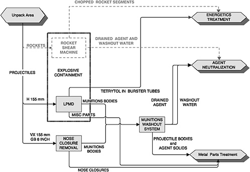
FIGURE 3-1 Rocket and projectile disassembly flow diagram. There are two RSMs, each in a separate ECR. Each RSM consists of a punch-and-drain section followed by a cutting station. The agent and washout water from the punch-and-drain station flow to agent neutralization, while energetics (propellant, bursters, and fuzes) are sent to energetics treatment as segments cut from the drained rocket. Miscellaneous projectile parts are carried in baskets or other containers placed in the projectile body trays and concurrently moved to the MPT with the projectile bodies as they are processed through the MWS. SOURCE: Briefing by the Bechtel Parsons Blue Grass team to the BGCAPP MDB Design Review, February 15, 2005.
MCE was accepted by the Department of Defense Explosive Safety Board. The design team has chosen to install bollards along the walls of the UPA to keep loads containing explosives from being placed or moved near the walls. This allows a somewhat lower blast loading for the UPA wall design. The dimensions of the UPA are sized to yield the area required for EONCs containing munitions with energetic materials in them.
Once in the UPA, the EONC atmosphere is sampled and monitored for agent. If agent is detected, the EONC is moved past the explosion containment vestibules (ECVs) to an airlock connected to the EONC leaker unpack station adjacent to the toxic maintenance area (TMA). The EONC is then moved through the airlock into the leaker unpack station, where operations personnel clad in appropriate personal protective equipment open the EONC and unload the munitions pallet. The leaking munition(s) are located and placed in overpacks for later processing. The remaining munitions are then placed in trays that are transferred on roller conveyors through an airlock to the adjacent ECV, where the munitions are then transferred into the associated explosion containment room (ECR) for disassembly. The ECV provides for pressure gradient control of contamination between the UPA (higher pressure) and ECR (lower pressure). The EONC is then
|
|
tion and explosives. The event must be realistic and have a reasonable probability of occurrence considering the explosive propagation, burning rate characteristics, and physical protection given to the items involved. The MCE estimated in this way may then be used as a basis for effects calculations and casualty predictions. |
decontaminated to the appropriate airborne exposure limit (AEL), and moved back out of the TMA through the EONC airlock.3 The decontaminated EONC is then returned to service.
If there is no detectable agent in the EONC atmosphere, the EONC is moved in the UPA near the ECV assigned for the munitions in the EONC. Both ECVs can be used for processing rockets, while only one of the ECVs is used to process projectiles containing bursters before bringing them into the ECR containing the LPMD.
In the ECV, the EONC is opened and the munitions pallet is unloaded by forklift and placed at the appropriate location for feeding individual munitions into the disassembly process through the ECV airlock. Individual munitions are removed from the pallet and transferred to a feed conveyor using an appropriate lifting device.
Strapping and other packing material are removed and collected for transfer to the secondary waste treatment area along with the pallets. Currently, it is not planned to process dunnage that has never been in a storage igloo with a record of agent leakage because such dunnage is presumed to be agent-free. There have been relatively few leakers at BGAD, as noted below, so most of the dunnage is not contaminated. This agent-free material will be moved to an area designated for materials to be disposed of off-site without further decontamination.
Miscellaneous Items
Bulk agents stored at Blue Grass Army Depot (BGAD) (i.e., one ton container of GB, one DOT bottle of VX, and two DOT bottles of H) will be processed at the end of the destruction campaign for each agent. These items will be moved from the CHB through the UPA airlock to the TMA airlock and then into the TMA, where they will be processed manually using appropriate personal protective equipment. Manual processing will be based on experience gained at other chemical agent destruction facilities processing similar containers and agents.
Processing of Leaking Munitions
As of May 2005, there were 55 H and 76 GB projectiles reported as leakers at BGAD.4 No VX leakers have been reported.
Overpacked leaking projectiles with and without bursters will be transferred into an ECR and opened on the reject table. If bursters are present, they will then be removed and sent to the energetics batch hydrolyzer (EBH). All leakers will be processed through the LPMD machine to verify the absence of a burster and then placed in a tray for transfer to the munitions washout system (MWS) room for agent removal.
The population of overpacked leaking rockets as of May 2005 was reported to comprise 91 GB rockets; there were no overpacked VX rockets.5 Overpacked rockets containing a particular agent will be processed at the end of the campaign for nonleaking rockets containing the same agent. The same equipment will be used for draining and washout of agent and for shearing the rockets.
Unpacking Projectiles Without Bursters
Pallets containing 155-mm VX projectiles or 8-inch GB projectiles without bursters are delivered in front of the airlock door between the UPA and the nose closure removal (NCR) room, where they are unpacked and placed in trays using a jib crane. The trays are then moved through the airlock and into the NCR room using roller conveyors. In the NCR room, the projectiles are placed horizontally in an NCR machine by a Fanuc-2000 multiaxis robotic arm. The NCR machine is the same as that used in the baseline design. In the NCR machine, the nose closure is removed and placed in a container along with other nose closures. The projectile burster well is tested to verify the absence of a burster, and the projectile is lifted by the robotic arm, rotated, and placed vertically in a tray for conveying to the MWS room. The container with nose closures is also placed in the tray being moved to the MWS room.
The container of nose closures is not processed by the MWS but simply proceeds on the same tray along with the projectile bodies on their way to the metal parts treater (MPT).
ACCESSING OF AGENT AND ENERGETICS IN GB AND VX M55 ROCKETS
The rocket handling sequence to be used at BGCAPP is the same as that used in baseline system facilities (see Figure 3-1). Rockets on pallets are removed from an EONC and moved to the rocket metering system, where the individual rockets in their firing tubes are removed from the pallets, checked for orientation (nose first), and placed on roller conveyors for movement through an airlock into an ECV for feeding into the associated ECR through a blast-resistant door. The ECV conveyor is segmented and has a swing section in the middle to permit maintenance personnel in demilitarization protective ensemble (DPE) suits to pass through.
In the ECR, the rocket in its firing tube is placed in the first position in the RSM, where the warhead cavity that contains agent is punched and drained of liquid agent and then washed out. The RSM is basically the same design as that used in the baseline processes, with minor modifications for punching and draining the agent and for cutting the rockets.
The RSM uses top and bottom punches to access the agent cavity in the warhead and to drain and wash out liquid and solid agent and other degradation products. The baseline RSM is not washed out after draining. There are two top punches with spray heads for supplying washout liquid and three bottom punches for draining agent and washout liquid. Both top and bottom punches penetrate the firing tube and warhead cavity off center to avoid hitting the burster. The firing tube is gripped tightly and crushed to prevent the rocket from rotating inside the tube. The bottom punches are designed to punch the aluminum warhead at an angle that bends but does not break off aluminum from the punch area of the warhead in order to minimize aluminum fragments in the drained agent or washout liquid. Any aluminum fragments released by the punch-and-drain operations will be caught on a drain system filter, which will be periodically checked and cleared by operations personnel in suitable personal protective equipment. A similar approach is used for baseline RSM operations. After draining, warm (77°F) pressurized water (>400 psig) is sprayed into the warhead agent cavity through the top holes to dissolve and wash out gelled and crystallized material formed during prolonged agent storage. The advantage of the power water wash over the gravity drain used in the baseline process is that all gelled agent and other solids such as the GB crystals are removed from the warhead. The drained agent and the wash water are sent to the agent storage tank in the toxic agent storage room.
The preceding drain-and-washout method was verified for the modified punch-and-drain equipment in TRRP 5d testing. This testing has been completed and demonstrates the washout capability and throughput rates for each agent. Test reports indicate success in all aspects of the washout operation.6 The tests have provided information to improve the design of the punch-and-drain probes.
After draining and washout, the rocket grippers are released and the rocket is rotated 90 degrees to minimize drips outside the drain station. The rocket in its firing tube is then moved forward to the rocket shearing station, where a hydraulically operated shear cuts the rocket into nine segments (eight cuts required), beginning with the nose section. The cut points are shown in Figure 3-2. The baseline RSM produces eight segments (seven cuts required). The additional segment produced by the RSMs at BGCAPP is a consequence of the cuts (particularly Cut 4) being placed to minimize the amount of aluminum that is delivered to the EBH during hydrolysis of M28 propellant (see Chapter 4 for a further discussion of EBH operations). Figure 3-3 shows details of Cut 4.
As of February 2005, the Bechtel Parsons Blue Grass Team was planning to further modify the RSM design by incorporating a special cutting tool for the cutting positions at the interface of the rocket warhead and rocket propellant sections (Cut 4) and at the interface of the rocket tailfin and rocket propellant sections (Cut 8). This special cutting tool would be based on the standard disc-type pipe cutter. It cuts by rotating three cutting wheels around the body while the wheels are gradually moved inward toward the longitudinal axis of the rocket. This modification was proposed to address the difficulty of shearing at Cut 4 and Cut 8. Cut 4 is very close to the propellant igniter, and there is a risk of initiating the igniter if the cutter happens to strike it. The longitudinal location of the rocket inside
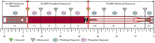
FIGURE 3-2 Cut points for RSM cutting of M55 rockets. SOURCE: Bechtel Parsons Blue Grass Team responses on May 2, 2005, to committee questions of April 25, 2005.
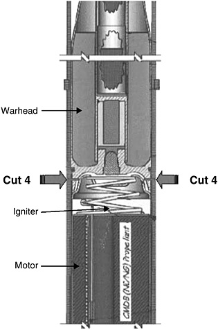
FIGURE 3-3 Detail drawing showing planned BGCAPP RSM Cut 4 of M55 rockets. SOURCE: U.S. Army and Bechtel Parsons Blue Grass Team responses on May 2, 2005, to committee questions of April 25, 2005.
the firing tube may vary by as much as ±0.5 inch, and the rocket shear positioning system will have a longitudinal positioning variance. The disc-type cutter is not any more precise than the shearing blade in locating a longitudinal cut, but it will not cut deep enough into the rocket to interfere with the igniter. Cut 8, shown in Figure 3-2, involves cutting through a part of the steel rocket nozzle just above the tail fins. Shear tests at this point have shown incomplete cuts.
Tests are planned as a part of TRRP 12 to demonstrate the efficacy of both the shears and cutting disks. This TRRP also will involve using a magnetic detector to precisely locate the magnetic/nonmagnetic seam between the rocket motor casing and the rocket warhead through the shipping and firing tube. The tolerance desired for this demarcation alone is 0.125 inch. The idea is to cut forward of the spring and the section called the “fore closure,” an end cap that holds the spring in place and screws into the front end of the rocket motor casing.
Each rocket segment with its associated fiberglass firing tube segment is collected in a bucket. Two collection buckets are used for each rocket. One bucket receives the washed-out warhead sections, including burster segments, the fuze, and the segment containing the aluminum tail-fin section from the preceding rocket. The other bucket receives the propellant-containing segments, including the propellant igniter and the smallest possible amount of aluminum from the adjacent warhead section. This segregation is necessary because the rocket propellant has been found to
ignite and burn briefly when aluminum is present during hydrolysis using a caustic solution. This phenomenon is discussed in detail in Chapter 4.
The buckets containing warhead and tail-fin segments or propellant segments are then moved on a conveyor to a position near the blast-resistant door leading to the EBH room. A deluge system is provided on the RSM to extinguish fires in the buckets in the unlikely event they should occur as a consequence of propellant ignition (owing, perhaps, to some mechanical stimulus involving sufficient impact or friction).
The buckets are then picked up by a multiaxis robotic arm and moved through a blast-resistant door, where they are placed in the airlock between the ECR and the EBH room. Subsequently, a Fanuc-2000 multiaxis robotic arm in the EBH room picks up the bucket from the airlock using an end effecter designed for carrying the buckets. The robot raises the bucket to a platform at approximately the height of the EBHs, from which it is moved by another robotic arm to one of the EBHs. As noted above, two buckets are needed for each rocket processed. The peak target rate, 48 rockets per hour, occurs during VX rocket processing. Thus, 24 × 2, or 48, buckets transfer through the airlock from each RSM ECR to the respective EBH ECR. This requires one bucket transfer every 75 seconds for each airlock. For GB rocket processing, the peak target rate is 40 rockets per hour, or 20 rockets per RSM per hour. Bucket transfers occur at a peak target rate of 90 seconds from each RSM ECR. According to the system design description, maintenance and other downtime are expected to cut average processing rates to about 30 rockets per hour (15 per RSM) for VX and 25 rockets per hour (12.5 per RSM) for GB.
There are also 24 M56 rocket warheads filled with GB stored at BGAD. These warheads, which are stored in overpacks, will be processed in the RSMs at the end of the GB rocket campaign. Spacers as long as the rocket section that the warhead would normally be attached to in an assembled rocket will be used to facilitate indexing of the warhead in the RSM. It is currently anticipated that the overpacked warheads will be unloaded from the EONC in the TMA and then moved on conveyors into the ECV, where they will be unpacked by personnel in DPE suits and fed onto the rocket input conveyor along with a simulated rocket motor section. The warheads will be processed through the same punch, drain, and washout station of the RSM used for the M55 rockets prior to being sheared and fed to the EBH system. During the preoperational systemization period for BGCAPP, the handling of these warheads will be tested using simulated warheads that have been modified with ogive sections for a closer approximation of the actual warhead’s configuration.7
Finding 3-1. The cutting of rockets in a way that avoids or minimizes mixing aluminum with propellant will be difficult and could involve high risk of propellant ignition, depending on where Cut 4, which is near the rocket igniter, is made. To minimize the chance of accidental ignition during cutting, it is important to know the dimensional variations that might occur in the position of the rockets inside their firing tubes and in the positioning of the firing tubes themselves. The current plan is to use magnetic detectors to locate the transition between the aluminum warhead and the steel tube holding the rocket propellant and, thereby, to achieve adequate separation of aluminum and propellant in batches transferred to the EBHs.
Recommendation 3-1. The use of magnetic detectors to locate the transition between M55 rocket aluminum warheads and the steel tubes holding the rocket propellant may be appropriate to ensure safe and proper cutting, but the technique should be thoroughly demonstrated to guarantee reliability. Also, the safe management of any reactions occurring during hydrolysis of small amounts of propellant and the propellant igniter with aluminum warhead segments in the EBH requires suitable evaluation. Precluding vigorous reactions could eliminate the need for accurate location of the warhead-motor transition point at Cut 4 and the potential ignition hazard associated with cutting near the propellant igniter.
Finding 3-2. The committee believes that separating cut rocket segments into buckets containing propellant and buckets containing aluminum warhead segments will require reliable software for managing the robotic feeding of the segments to the EBH system.
Recommendation 3-2. Procedures, as well as software protections, should be developed to prevent mistakes such as incorrect mixing of rocket segments when manual overrides are activated during handling system failures or upsets. This can help prevent restarts out of proper sequence.
Finding 3-3. The Bechtel Parsons Blue Grass Team plans to demonstrate the processing of M56 warheads during systemization using simulated warheads. Delaying this demonstration until systemization greatly increases the risk that the start of operations could be delayed by the need for design changes.
Recommendation 3-3. The efficacy of planned M56 warhead processing should be evaluated in conjunction with the scheduled testing of the modified rocket shear machine prior to systemization.
ACCESSING OF ENERGETICS IN PROJECTILES
Pallets with 155-mm projectiles containing H and bursters are unpacked by placing the pallets in front of the airlock for the ECV that feeds the ECR containing the LPMD machine. The projectiles are removed from their pallets in the UPA and moved by conveyor into the ECV, where they are placed in trays using a jib crane. The trays loaded with projectiles are then transferred into the ECR through a blast door to the unloading position, where a multiaxis pedestal-mounted robotic arm picks each projectile from the tray and moves it progressively in a nose-up orientation through three disassembly stations in the LPMD machine to remove (1) the nose closure, (2) miscellaneous small parts such as spacers and springs, and (3) the burster. As noted earlier, the LPMD machine was evaluated before selecting a projectile/mortar disassembly (PMD) machine for PCAPP. This evaluation concluded that the baseline PMD machine, a horizontal rotary arrangement of disassembly stations, could be replaced by installing the stations in a row or line, oriented for operation on projectiles that are in a vertical position. The projectiles are moved between these stations using a commercially available multiaxis robotic arm used in assembly lines requiring precise positioning. For BGCAPP, another trade study, TRRP 1, was conducted to confirm the advantage of the LPMD machine over the baseline design (see Table 2-2). This trade study confirmed the efficacy of the LPMD machine for use in BGCAPP (Bechtel Parsons, 2004d).
The projectile body, still containing agent in the cavity between the burster well and projectile body, is transferred by the robotic arm and placed horizontally on a conveyor. It then is conveyed from the ECR through a blast door to a position in the TMA where another robotic arm lifts and places the projectile body nose up in a tray. When filled, the tray is transferred on roller conveyors into the airlock feeding the MWS room (see Figure 3-1).
Only one of the two ECRs is equipped with an LPMD machine, which will be installed during construction but not used until the H campaign. Before the ECR containing the LPMD machine is used for the H campaign, it will be used to process GB- and VX-containing rockets in the RSM that is also installed in it. During the rocket processing campaigns, the LPMD machine will be covered with a suitable plastic to protect against corrosive process fluids. The installation of both the LPMD machine and the RSM in the ECR during construction will facilitate quick mechanical changeover to H processing at the conclusion of the rocket campaigns.
As many as three projectiles may be in some stage of disassembly at the same time. The metal parts, fuze cups, and burster removed in the LPMD machine stations are moved by conveyor to a bucket similar to that used for rocket segments. The bucket follows the same path that buckets containing rocket segments follow into the EBH room and the EBHs; however, for projectiles there is no requirement for segregation of projectile parts as there is for processing rocket segments, since the projectiles contain no propellant or aluminum.
Reject projectiles in which some part of the disassembly process cannot be accomplished by the LPMD machine are moved to a reject stand by the robotic arm for future manual processing. The current reject stand design allows for up to three rejects to be stored before calling in specialists or explosive ordnance disposal personnel in DPE suits to manually complete disassembly.
Finding 3-4. The LPMD machine design for BGCAPP appears to be capable of reliably performing the disassembly of projectiles at the desired rate. It uses established baseline disassembly tools and a commercial robotic handling system with high positioning accuracy.
Recommendation 3-4. While the LPMD machine is considered a good candidate for projectile disassembly, it is recommended that it be shop tested and systematized prior to installation to confirm its effectiveness.
ACCESSING OF AGENT IN PROJECTILES BY MUNITIONS WASHOUT SYSTEM
Agent is removed from projectiles by the cavity access machines (CAMs) of the MWS. The same MWS will be used for GB-, VX-, and H-containing projectiles, with H being the last campaign. Projectiles containing GB or VX are delivered to the MWS room in trays from the NCR room. As previously stated, the nose closures associated with these projectiles were placed in a special container on the projectile trays for subsequent treatment along with the washed-out projectile bodies in one of the MPTs. Also as noted earlier, H projectiles with energetics and nose closures removed will also be transferred by being placed in trays in the TMA and moved on the NCR conveyor feeding the MWS room.
In the MWS room, a Fanuc-2000 multiaxis pedestal-mounted robotic arm enshrouded in a flexible protective cover is used to accomplish the following:
-
Lift each agent-containing projectile from a feed tray.
-
Place the projectile in a weighing station to ascertain weight and to verify the absence of a burster. (For H projectiles, the LPMD will include a burster probe to verify burster removal. Thus, H projectiles will be tested twice for the absence of a burster.)
-
Move and invert the projectile and place it in a CAM for punching the burster well into the agent cavity, draining of the agent, and high-pressure washing out of the agent cavity.
-
Slightly lift and tip the projectile on the CAM drain to remove the final drops of liquid, remove the washed-out projectile from the CAM, rotate it nose up, and place it in the weighing station for a tare weight.
After weighing and determining that the weight reduction is within target values (that is, that less than 2 percent of agent remains), the washed-out projectile is placed by the robotic arm in the discharge tray. If the weight reduction is less than specified, the projectile will be returned to the CAM for additional washout.
The CAM is identical in design and operation to the CAM planned for the Pueblo Chemical Agent Destruction Pilot Plant (PCAPP). It uses a ram to force and bend the burster well up into the agent cavity, allowing liquid agent to drain by gravity to an agent collection tank. The CAM is housed in a booth to reduce decontamination requirements during closure.
After draining liquid agent, 10,000 psig wash water at 110°F is sprayed into the cavity through a nozzle in the burster well ram head to wash out gelled and solid materials. The design is the same as for PCAPP except for a larger size being used for 8-inch projectile bodies. TRRP 5a provides for testing of the MWS system for both 155-mm and 8-inch projectiles. As of February 15, 2005, 155-mm testing had been successfully completed and 8-inch projectile testing was under way.


