
4
Core Processes for Agent and Energetics Destruction
AGENT HYDROLYSIS
Agent Hydrolysis Chemistry
The neutralization of the pure nerve agents GB and VX with caustic (aqueous NaOH) and of mustard agent with water has been extensively studied by the U.S. Army and its support contractors (Yang et al., 1988, 1992; Yang, 1999). The Army and its contractor, Bechtel, had already optimized the hydrolysis process to efficiently destroy the bulk mustard stored at Aberdeen Proving Ground in Maryland. Chemical neutralization with caustic is also being used to destroy the bulk VX stored at Newport, Indiana. Also, earlier National Research Council (NRC) committees involved with the Army’s Assembled Chemical Weapons Assessment program reviewed the chemistry and the efficacy of neutralization of these agents with caustic (NRC, 1999, 2000, 2001a, 2001b, 2002a, 2002b, 2002c).
However, because the neutralization of GB by hydrolysis has not been used at any other sites, a technical risk reduction project (TRRP) on GB neutralization for BGCAPP has been initiated. TRRP 2a, GB Neutralization Analytical Methods, is expected to verify process design assumptions, including the efficacy of the batch process, to obtain background kinetics data, and to validate the analytical method detection limits in hydrolysate for degraded GB found in actual stored munitions. Liquid GB and solid GB residues removed from M55 GB rockets that were processed at the Anniston, Alabama, baseline system facility early in 2004 are being used in the tests.1
TRRP 2b, H vs. HD Neutralization Analytical Methods, has exactly the same objectives as TRRP 2a but is used for the Levinstein form of mustard agent in the munitions at BGAD. Previous studies had been performed on distilled mustard agent (HD) and HT.2 In the TRRP 2b tests, samples of liquid H and solid H obtained from 155-mm projectiles stored at Deseret Chemical Depot in Utah are being used. These are the same samples used during ACWA testing of the munitions washout system (MWS) design in June 2003.3 TRRP 2b has been completed, but the report has not been made available to the committee.
Studies of the neutralization of VX were not needed because they had already been performed in support of the Newport Chemical Agent Disposal Facility design. However, a new TRRP 11 activity, A Hardened Method for Detection of VX in Hydrolysates, was initiated recently to determine an acceptable procedure
for measuring the presence of VX in the hydrolysate.4 Samples of hydrolysate made from VX collected in early 2004 from ton containers at the Newport site are to be used.5 These samples are presumed to be similar in composition to those in the munitions at Blue Grass Army Depot (BGAD).
Another TRRP activity, TRRP 6, ANS Reactor Material and Corrosion Study, is a trade study that has been completed, but the final report had not been released when this report was prepared.6 The committee understands that the study confirmed the appropriateness of the original selection of commonly available reactor materials to be used in constructing the agent neutralization system (ANS).
Agent Collection System
The process for removing agent from projectiles and M55 rockets was described in Chapter 3. The agent drained from the rockets in the rocket shear machine (RSM) and from the projectiles at the MWS is collected in the agent collection system (ACS). The purpose of the ACS is to (1) collect agent drained from the munitions, (2) provide storage for excess agent spill or overflow if needed, and (3) collect the agent wash water from the MWS and RSM. The ACS includes a holding tank for agent and a surge tank. The surge tank is normally empty. Vent gases are directed to the metal parts treater (MPT) offgas treatment system. The agent is collected and remains in the tank until it is sent to the ANS.
The agent wash water from the high-pressure washes performed during MWS and RSM operations is collected in a spent decontamination fluid/agent washout water holding tank. The washout water solution, which consists of water along with some washed-out agent, is added to the agent hydrolyzers as part of the recipe for destruction of the agent that has been drained and washed out of the munition. (Bechtel Parsons, 2004e, 2004f).
The Bechtel Parsons Blue Grass Team has not decided yet how to handle the solids that are present and collected along with the liquid chemical agent in the process. The GB munitions contain crystals of diisopropylurea, which is formed by the reaction of the stabilizer, diisopropyl carbodiimide (commonly denoted DICDI), with acid in impure GB. Approximately 5,000 rockets and 3,000 projectiles are expected to have water-insoluble crystals. The crystals are not soluble in the regular process fluids and can plug the lines. In a recent solubility study, the crystals were found to be soluble in alcohols, including isopropyl alcohol, methanol, and isobutyl alcohol.7
The Bechtel Parsons Blue Grass Team has initiated laboratory tests under TRRP 2a, Phase 2, to study the effect of dissolving the crystals in isopropyl alcohol on the reaction parameters and the downstream processing equipment. Alternative methods of treating the crystals will be studied. As this report was being prepared, the plan was to separate the crystals and send them directly to the MPT for destruction.
Earlier studies reported finding a gel in some GB munitions. However, no gel remains in the munitions after washout. Thus, if gel were to be present in a munition, it would be washed out by the hot water.
GB taken from rockets at the Anniston, Alabama, site also contains some debris made up of fiberglass fibers, polymers, and white and grey dust (Rosso et al., 2005). The mustard projectiles also contain particles of iron, sulfur, and several minor solid contaminants that must be separated from the agent liquid. Strainers are proposed to remove the particles from the liquid streams from the RSMs and the cavity access machines of the MWS. The strainers that catch the particles will be periodically changed out by personnel in DPE and placed in a container for transfer to the MPT for decontamination or destruction.
Agent Neutralization System
The purpose of the agent neutralization system is to (1) neutralize the chemical agents, (2) process agent-contaminated spent decontamination solution and MPT condensate, (3) sample and analyze the hydrolysate to ensure a destruction level of 99.9999 percent, and finally, (4) transfer agent-cleared hydrolysate to the hydrolysate storage tanks to await further treatment in the supercritical water oxidation (SCWO) system.
The process flow diagram is given in Figure 4-1. Two complete ANS lines are required to handle peak throughput rates for agent. Design parameters and
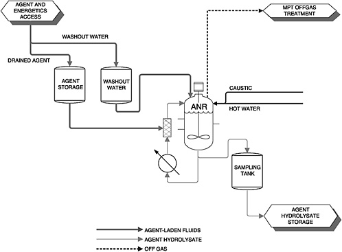
FIGURE 4-1 Flow diagram for the agent neutralization system. SOURCE: Chris Haynes, “BGCAPP MDB Intermediate Design,” briefing to the BGCAPP MDB Design Review, on February 15, 2005.
specifications for the hydrolysis of each type of agent are given in Table 4-1.
At the start of an agent processing cycle, an agent neutralization reactor (ANR) is charged first with demineralized water. The prescribed amount of caustic solution is then added if GB or VX is being treated. Any contaminated wash waters are added next. Finally, over the next 20 minutes, agent from the agent concentrate holding tank is added. The contents of the ANR are both stirred and recirculated to maintain good mixing. The target concentrations for the three agents and the prescribed conditions and processing time for each agent are shown in Table 4-1.
When mustard agent is being processed, only water is used as the neutralization medium and HCl is generated by hydrolysis. Caustic is added after 45 minutes to react with the HCl and bring the pH to 10.5. During the next 30 minutes, small amounts of caustic are added to maintain the pH at 10.5 while the hydrolysis of reaction intermediates and byproducts, mainly linear sulfonium ions, continues.8
If mustard agent or GB is being treated, the hydrolysate is transferred to a 2,000-gallon sampling tank when the reaction is completed. The agitated sampling tank holds two batches of hydrolysate. The holding tanks with the recirculating sampling loop are continuously
TABLE 4-1 Agent Neutralization Parameters
|
|
Agent |
||
|
GB |
VX |
H |
|
|
Agent process feed concentrations |
|
|
|
|
Agent (wt%) |
7.5 |
16.6 |
8.6 |
|
Caustic (wt%) (from 50% NaOH) |
11.34 |
17.44 |
Added after to adjust pH to 10-12 |
|
Water (wt%) |
81.16 |
65.96 |
91.4 |
|
System parameters and performance specifications |
|
|
|
|
Operating temperature (°F) |
140 |
194 |
194 |
|
Peak rate baseline (units per hour) |
40 GB rockets 15 GB projectiles |
48 VX rockets 26 H projectiles |
26 H projectiles |
|
Peak rate (lb agent/day)a |
15,540 |
15,379 |
7,301 |
|
Total time per batch (min) |
168 |
516 |
243 |
|
Batches per reactor per day |
6 |
2.5 |
2.5 |
|
Total weight of agent to be destroyed (tons) |
305.7 |
127.2 |
90.63 |
|
Maximum agent concentration to achieve 99.9999% destruction efficiency (ppb) |
75 |
160 |
85 |
|
aThe peak rate is the maximum expected rate during a campaign. Normal operating rates will be lower. Peak rate agent volumes have been multiplied by a safety factor of 1.25 for the purpose of sizing the tanks and other critical materials handling equipment. The total number of batches per day is less than what can be processed in 24 hours, again providing a design safety margin. SOURCE: Bechtel Parsons, 2004e. |
|||
stirred to prevent the solution from separating into two phases and to allow a representative sample to be obtained. The contents are analyzed to verify that the agent concentration is destroyed to 99.9999 percent of the original amount. The maximum agent concentrations allowed in the hydrolysates to satisfy this destruction and removal efficiency are given in Table 4-1.
Upon verification that the agent concentration is below the limit to achieve 99.9999 percent destruction, the hydrolysate is transferred to one of the tanks in the hydrolysate storage area. In contrast to the sampling protocol for H and GB, wherein samples are taken from a sampling loop attached to the ANR, the VX hydrolysate is sampled directly in the ANR. If the VX concentration in the hydrolysate indicates 99.9999 percent destruction, the hydrolysate is transferred directly to a storage tank that is continually stirred and recirculated to prevent the aqueous and organic layers from separating.9 The hydrolysates are stored until they are treated in the SCWO units.
Analysis Issues Concerning Agent Destruction Removal Efficiency
Determining the concentration of GB in the hydrolysate has been problematic. Battelle used a method that involved neutralization of the hydrolysate, extraction of the organic components into an organic solvent (chloroform, methylene chloride, or hexane), and determination of the GB content by a gas chromatograph/ mass selective detector. TRRP 2a, GB Neutralization Analytical Methods, was initiated when GB was de-
tected in the hydrolysate of a sample that should have had no detectable GB based on the kinetics of decomposition of GB in caustic at elevated temperature.10
Preliminary studies undertaken for TRRP 2a indicate that reformation of GB does not take place when the pH of the aqueous phase (hydrolysate) is high or even near neutral. Tests indicated that GB reformation in organic extracts began above 190°C. It was found that reformation was occurring in the gas chromatograph/mass selective detector injector, where a high temperature is used to flash-vaporize the analyte. A modified procedure was developed using a Hewlett-Packard cool-on column capillary injector that does not heat the analyte and avoids GB reformation. The analyte is heated directly by the column at well below 190°C. The new procedure was confirmed with GB recovery studies, and reliable measurements were obtained, showing that no GB reformation occurs in hydrolysates at neutral or high pH.11
Similar analytical problems exist with the analysis of VX in the hydrolysate. Originally, the Bechtel Parsons Blue Grass Team hoped this problem would be resolved at Newport, but now has initiated TRRP 11, VX Hydrolysis Analytical Methods Test, to resolve this issue. The analysis of mustard agent in the hydrolysate does not pose any problem.
When nerve agent hydrolysates are transferred from the munitions demilitarization building (MDB) to the agent hydrolysate storage tanks, the pH will be above 10. VX and GB hydrolysates will be stored at a pH of between 11 and 13.12 Thus, there is no possibility that the agent will be reformed. Caustic will be added to the mustard agent hydrolysate to neutralize the HCl generated by the hydrolysis and to promote the decomposition of intermediates formed in the hydrolysis of H. Then, more caustic will be added to adjust the pH to between 10 and 12.
Finding 4-1. Given the experience of the Army’s chemical demilitarization program with mustard hydrolysis at Aberdeen, Maryland, VX hydrolysis at Newport, Indiana, and prior laboratory testing with all agents, including GB, the hydrolysis (neutralization) of these agents at BGCAPP should pose no insurmountable difficulties.
Potential Contamination of Mustard Agent with Mercury
Mercury has been found in HD at other locations, including at Deseret Chemical Depot, Utah. Several theories exist for its source, including contamination from mercury diffusion vacuum pumps used in the distillation, mercury from broken manometers that were allowed to contaminate the HD, and residual mercury in containers that were used for HD storage. Insufficient Levenstein mustard has been sampled at Deseret Chemical Depot to predict the mercury concentration in the mustard agent hydrolysate that will be produced at BGCAPP and how much would be volatilized into the offgas streams. An unexpectedly high concentration of mercury in the offgas streams or hydrolysates might impact the BGCAPP design or delay its start-up. Also, the form of the mercury in the Levenstein mustard is unknown and cannot be predicted, since the mercury may have undergone transformation during storage.
Finding 4-2. The form of the mercury and its concentration in the Levenstein mustard is unknown at this time.
Recommendation 4-2. A design analysis should be performed to determine the potential impact of mercury in the Levenstein mustard on the operation or permitting of BGCAPP. One scenario that should be evaluated is the impact of mercury if the Levenstein mustard stored at BGAD contains mercury in concentrations as high as those observed for HD and HT at other locations.
ENERGETICS HYDROLYSIS
Energetics Hydrolysis Chemistry
Caustic hydrolysis is the basic process used in the BGCAPP design for the destruction of the rocket propellant grains and the other energetics (igniters, fuzes, and bursters). This technology was previously demonstrated to be suitable for the destruction of the energetic materials in the stockpile at BGAD (NRC, 2002a). The particular means of implementing caustic hydrolysis at BGCAPP is the energetics batch hydrolyzer
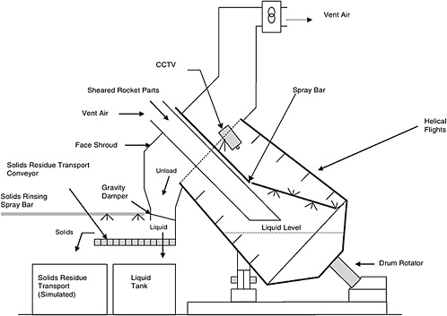
FIGURE 4-2 Drawing of EBH design for BGCAPP. SOURCE: John Ursillo, Bechtel, “Process design overview (Blue Grass),” briefing to the committee on September 22, 2004.
(EBH), which is described in detail below and shown schematically in Figure 4-2. The specific conditions to be used for the EBHs were selected based on the outcome of the EBH hydrolysis tests performed at Tooele Army Depot (Bechtel Parsons, 2004g) and on testing performed for the energetics rotary hydrolyzer designed to process energetics at the Pueblo Chemical Agent Destruction Pilot Plant.13 The latter included testing of the hydrolysis reactions of the energetics rotary hydrolyzer in a single-flight reactor at the Tooele Army Depot for the Demo 1 phase of the Assembled Chemical Weapons Assessment program and later testing while the reactor was located at Dugway Proving Ground for the engineering design studies phase of the program.14 This testing is applicable to the EBH design proposed for BGCAPP.
At the start of each cycle, each EBH is charged with water and 50 percent NaOH to give a concentration of 39.5 percent caustic. The EBHs are operated at 122°C for the propellants and at 117°C for the burster materials. Testing at Tooele Army Depot confirmed that hydrolysis of rocket motor propellant is completed in less than 3 hours at these temperatures and that hydrolysis of the energetics from the warhead is complete in less than 45 minutes (Bechtel Parsons, 2004g).
The energetic materials to be treated at BGCAPP are listed in Table 4-2. The bulk of the energetics comes
TABLE 4-2 Energetic Materials in BGAD Chemical Munitions
|
Munition/Component |
Energetic Material |
Composition |
|
M55 rockets/rocket motor |
M28 propellant |
60.0% nitrocellulose 23.8% nitroglycerin 9.9% triacetin 2.6% dimethyl phthalate 2.0% lead stearate 1.7% 2-nitrodiphenylamine |
|
M55 rockets/igniter |
M62 igniter pellets |
49% magnesium 49% potassium perchlorate 2% cellulose nitrate-camphor (MIL-B-10854) |
|
|
M2 electric squib flash charge |
32% lead thiocyanate 40% potassium chlorate 18% charcoal 10% Egyptian lacquer |
|
M55 rockets/ M417 point |
detonating fuze NOL primer mix (upper lead charge) |
40% lead styphnate 20% lead azide 20% barium nitrate 15% antimony sulfide 5% tetracene |
|
|
Lead azide (intermediate charge) |
100% lead azide |
|
|
M63 stab detonator (lower charge) |
98% RDX 2% calcium resinate-graphite |
|
|
RDX (booster pellet and booster lead charge) |
100% RDX |
|
M55 rockets/burster |
Composition B |
60% RDX 39% TNT 1% wax |
|
M110 projectiles/burster |
Tetrytol |
70% tetryl 30% TNT |
|
SOURCE: Meyer et al., 2002; U.S. Army, 1962, 1965, 1966. |
||
from the M55 rockets, each of which contains over 19 pounds of M28 propellant and over 3 pounds of Composition B. In contrast to this, the only projectiles that contain energetic materials are the mustard-loaded M110 projectiles, which have about 0.4 pounds of tetrytol in the steel-walled M6 burster.
The main gaseous products of the energetics hydrolysis are ammonia, nitrogen, carbon monoxide, and volatile hydrocarbons. Other main products of hydrolysis that have been identified are nitrate, nitrite, acetate and formate salts, and glycerol (when propellant is being processed). However, considerable quantities of unidentified carbonaceous compounds remain in the hydrolysate. The exact nature of these has not been established; in the case of explosives containing TNT or tetryl (Composition B and tetrytol), some of them are ill-defined aromatic compounds. The exact identity of these species is not in itself important, but it is important that they not be energetic materials. The hydrolysis process is effective in counteracting the hazard associated with the energetic nature of the energetic materials being treated (NRC, 2002a).
To address the issue of any latent explosion hazard from the hydrolysate, a differential scanning calorimetry method is currently under development for the analysis of residual energetic materials in the hydrolysate. This method gives an indication of possible exothermic decomposition reactions in the hydrolysate, in recognition of the fact that even if there is no TNT or RDX or tetryl present, there might still be an explosion hazard from partially decomposed energetic materials. At the time this report was prepared, no final report was available to the committee on the differential scanning calorimetry method to be used to clear the energetics hydrolysate for transfer to the energetics hydrolysate storage tanks.
EBH Input Streams
Following shearing of the M55 rockets in the RSM, the propellant segments are still encased in sections of the steel rocket motor body and surrounded by sections of the fiberglass shipping tube. All of these components are put into the EBHs. The steel body and the fiberglass sections are essentially unaffected by the hot caustic in the EBHs. The igniter assembly is encased in perforated polyethylene sheeting, which allows the caustic to contact the energetics in the igniter. The aluminum warhead assembly in the M55 rocket has a two-part burster system containing Composition B. The smaller M36 burster assembly is in a plastic casing, and the larger M34 burster is in a steel tube. The M417 point detonating fuze contains a variety of energetic materials in the fuze train (see Table 4-2), contained in an aluminum housing.15 Testing under TRRP 5b-1 showed that some of the explosive charges of the M417 fuze remain intact during their residence time in the EBH. The explosive-containing steel rotor assembly is to be processed with the rest of the warhead solid materials through a heated discharge conveyor (HDC), which is designed to withstand the exothermic decomposition (“popping”) of the explosive charges. The resulting waste would then be suitable for disposal in accordance with the BGCAPP permits.16
In addition to the energetic portions of the warhead sections that are treated in the EBHs, the tail fins, fore and aft end caps, and warhead bodies are made of aluminum and will also react with the caustic to form aluminates and elemental hydrogen.
As long as the pH is high, the aluminum will stay in solution in the hydrolysate. However, corrosion considerations require that the pH be lowered. This is achieved by the addition of hydrochloric and sulfuric acids. At the lower pH, aluminum salts precipitate from the solution and are removed by filtration.
The composition of the feed to the EBHs during processing of M55 rocket segments as described above gives rise to a propellant ignition issue. During one of the TRRP studies in which propellant was being hydrolyzed in the presence of aluminum, the propellant ignited on a few occasions.17 These ignitions were nonpropagating and were never observed when aluminum was not present. The Bechtel Parsons Blue Grass team has postulated that the highly exothermic reaction of the aluminum in the caustic, which generates hydrogen gas and aluminum-containing salts, can produce enough heat locally to cause the propellant to begin burning briefly. The proposed solution to this problem is to (1) locate the cuts in the rocket motors so that little or no propellant is present in the segments that have aluminum parts and (2) hydrolyze the propellant completely before adding any aluminum parts to the EBHs. The process by which this is done is described below. The problem does not occur with projectiles because they do not contain propellant.
Energetics Process Flow
As described in Chapter 3, when rockets and projectiles are disassembled, the energetic materials are segregated from the agent in the explosion containment rooms (ECRs) and the items containing energetic materials are placed in specially designed buckets, which are picked up by a robotic arm and moved into an airlock between the ECR and the EBH room. Other robots in the EBH room pick up the buckets from the airlock, raise them to a platform at the approximate level of the EBHs, and deposit them on the platform. One of two robotic arms, which are attached to separate monorails that run parallel to the row of EBHs, picks up the bucket and moves it to the inlet chute of one of the EBHs. The parts are dumped into the inlet chute and fall into the EBH, which has previously been charged with water and caustic and heated to give the desired concentration at the desired temperature.
The design for BGCAPP comprises two EBH rooms, each of which contains eight EBHs in a row. Each RSM is paired with an EBH line. The two EBH rooms are mirror images of each other and are separated by a blast containment wall.18 As shown in Figure 4-2, each EBH
is a rotating drum, 10 feet wide by 18.5 feet long, mounted at an angle (like a cement mixer), with a discontinuous helical flight to agitate the items containing energetics. The EBH is fitted with an inlet chute through which the energetics are introduced and an outlet chute through which hydrolysate and solid materials are discharged. The solids, consisting of metal and plastic parts from munitions and fiberglass shipping tube parts, are discharged onto a conveyor that carries them to a bucket elevator and metering screw feed system. The metering screw feed system discharges the solids onto the HDC. The hydrolysate is transferred through a Johnson screen to a 2,000-gallon hydrolysate collection tank (Bechtel Parsons, 2004h). The EBH drum rotates in one direction while the energetics are being processed; then the direction of rotation is reversed to discharge either the metal parts only if the rate of rotation is slow or the hydrolysate if the rate of rotation is fast.
The rockets contain both propellants and explosives, in contrast to the H projectiles, which contain explosives only in the bursters. When rockets are being processed, the rocket motor segments (containing propellant) produced by the RSM are placed in one bucket and the warhead segments (including energetics) are placed in another, together with the aluminum fins from the preceding rocket. This segregation of propellant and aluminum is necessary because, as noted in the preceding section, the Bechtel Parsons Blue Grass Team observed during testing that propellant could ignite in the hydrolysate if aluminum-containing parts were processed at the same time as the propellant. However, in TRRP 5b-1 tests, it was found that propellant hydrolysate that contained little or no residual propellant could be used to destroy the warhead energetics with no ignitions of energetic material in the EBH. The approach for charging feed materials to the EBHs, which reflected this TRRP testing, is described below (Bechtel Parsons, 2004c).
A graphical representation of the timing of the delivery of energetics to the EBHs is given in Figure 4-3. Following the filling of two EBHs with caustic over a period of 30 minutes, one bucket filled with the parts from one rocket motor is delivered to EBH-1, and another bucket filled with the warhead parts and fins is delivered to EBH-2. Over a 2-hour period and at a planned peak operating rate of 24 VX rockets per hour, there will be 48 deliveries each to EBH-1 and EBH-2—that is, 48 bucketfuls of rocket motor parts to EBH-1 and 48 bucketfuls of warhead parts and fins to EBH-2. At the end of this 2-hour period, the next batches of rocket motor parts and warhead energetics/ fins are delivered over the next 2-hour period to another pair of EBHs (EBH-3 and EBH-4). At the end of the second 2-hour period, the next pair of EBHs, EBH-5 and EBH-6, are loaded. After a total of 6 hours, the processing of the warhead energetics in EBH-2 is complete, the hydrolysate and residual solids have been removed, and the EBH has been refilled with caustic. Over the next 2 hours, 48 bucketfuls of rocket motor parts are delivered to EBH-2, while the corresponding deliveries of warhead energetics and fins go to EBH-7. Eight hours after the first rocket motor parts were delivered to EBH-1, EBH-4 is ready to receive rocket motor parts and EBH-1 is ready to receive warhead energetics and fins. Thus, over a 14-hour cycle, as summarized in Table 4-3, and at the planned peak operating rate of 24 VX rockets per hour, the propellant and warhead energetics from a total of 48 rockets will be destroyed in a given EBH.
When the RSMs are operating at the planned peak rate of 20 rockets per hour for GB and 24 rockets per
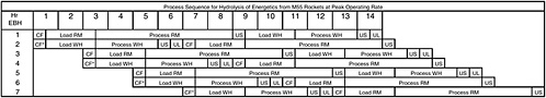
FIGURE 4-3 Peak VX EBH processing cycle. The caustic fill step marked by an asterisk is performed only when warhead segments are loaded first during the start of EBH processing, resulting in an initial cycle length of 14.5 hr: CF, caustic fill; US, unload solids; UL, unload liquid. SOURCE: Developed from “BGCAPP MDB Intermediate Design,” briefing to the BGCAPP MDB Design Review on February 15, 2005.
TABLE 4-3 EBH Processing Cycle Sequence for M55 Rocket Parts
|
Start Time |
Duration (hr:min) |
Operation |
|
0:00 |
0:30 |
Fill EBH with caustic |
|
0:30 |
2:00 |
Add rocket motors |
|
2:30 |
5:30 |
Process rocket motors |
|
8:00 |
0:30 |
Unload remaining solids from rocket motors |
|
8:30 |
2:00 |
Load energetics from warheads |
|
10:30 |
2:30 |
Process energetics from warheads |
|
13:00 |
0:30 |
Unload remaining solids from warheads |
|
13:30 |
0:30 |
Unload hydrolysate from EBH |
|
14:00 |
|
End of cycle |
|
SOURCE: Bechtel Parsons, 2004c. |
||
hour for VX, seven of the eight EBHs in each line will be in use. The eighth is to be used as a spare, in case there are mechanical problems with one of the other seven. This will allow repairs to be deferred and performed with other routine maintenance of the EBHs, and will prevent the processing of energetics from being interrupted.
The average processing rates are expected to be 12.4 and 14.9 rounds per hour for GB and VX rockets, respectively. In the throughput and availability analysis (Bechtel Parsons, 2004c), it is assumed that the length of time needed to complete destruction of the M28 propellant is 3 hours after introduction of the propellant into the EBH, and of Composition B, 2 hours (Bechtel Parsons, 2004g). The residence time of the propellant in the EBH, as shown in Table 4-3, greatly exceeds the time required for destruction of its energetic components. In the case of Composition B, it is assumed that 2 hours will be required for complete destruction of the energetics, but 3 hours (2.5 hours processing time with an additional 0.5 hour during which the metal parts are unloaded) are allowed. In any case, the assumption of 2 hours is itself conservative, since testing at Tooele Army Depot showed that the energetics are consumed in less than 45 minutes at the planned operating temperature. Therefore, by the time the hydrolysate is removed from the EBH, all of the energetics should have been destroyed.
At the end of the propellant processing step, the solids (shipping tube segments and rocket motor segments plus miscellaneous metal parts) are removed from the EBH by reversing the direction of the rotation and rotating the EBH slowly. The hydrolysate drains through the discontinuities (gaps) in the helical flight and remains in the EBH to be used for processing warhead energetics. The solids are pushed through the outlet chute onto a horizontal motion (slip) conveyor that is part of the EBH solid residue collection and transfer system. EBH operations were tested successfully in a full-scale mockup in TRRP 5b-2a, described in Table 2-2. Any liquid that is carried out with the metal parts drains off through Johnson screens in the outlet chute and is collected in a hydrolysate collection tank. At the end of the conveyor, the solids fall into a collection bin that is then raised by the solid residue transport system and tipped to deliver the solid residue into the HDC feed system. Here, an auger is used to meter the solids onto the HDC so that they are spread out on the conveyor. This particular transfer approach is being tested as part of TRRP 5b-2b. Test results were not available at the time this report was being prepared.
The metal parts and other solids are carried along the HDC, which is an electrically heated bucket conveyor, under a 600 pound per hour nitrogen gas purge stream, during which time they are subjected to 1000°F for 15 minutes to make them suitable for unrestricted release. At the end of the HDC, they are deposited on a cooling conveyor, from which they are transferred to a collection bin for removal and disposal. Operation of the HDC is being demonstrated as a part of TRRP 5b-1, as described in Table 2-2. Test results were not available at the time this report was being prepared.
After the residual solids from the rocket motors have been removed from the EBH, the hydrolysate remaining in the EBH is used for processing of warhead segments and the fin section. The main advantage of this cascading is that it produces a hydrolysate that has better flow characteristics than the hydrolysate that is produced from treatment of the propellants alone. At the end of the propellant processing step, there is a thick layer of cellulosic sludge floating on the surface of the hydrolysate. This sludge is broken down during the additional time required for the warhead energetics hydrolysis, and the resultant hydrolysate is all liquid.19 This processing scheme is consistent with the need to destroy the propellant in the absence of aluminum and does not require separate EBHs dedicated to propellant
processing or warhead energetics/aluminum parts processing.
At the end of the warhead energetics/aluminum parts processing step, the residual solids (burster tubes and steel parts from the fuze, at this point) are removed by reversing the direction of rotation of the drum and slowly rotating it to deliver the solids onto the EBH solid residue conveyor, as was done for the rocket motor parts. When the bulk of the solids has been removed, the rate of rotation is increased and the hydrolysate is pushed out of the EBH, where it drains through the screens in the outlet chute and is collected in a 2,000-gallon hydrolysate collection tank. The hydrolysate from several EBH cycles is accumulated in the collection tank and subsequently transferred to an energetics neutralization reactor (ENR). Each EBH line has one hydrolysate collection tank and three ENRs, each with a working capacity of 4,785 gallons.20
After the hydrolysate has been moved to one of the ENRs, it is analyzed for the presence of energetics and agent. If the analyses show that the hydrolysate has sufficiently low concentrations of energetics and agent (agent levels below those specified in Table 4-1; energetics below a level still to be determined), it is pumped to one of the hydrolysate storage tanks for later treatment in the SCWO reactors. If the analysis indicates the presence of energetic material or agent in excess of an acceptable level, the hydrolysate is treated in the ENR for 1 hour, then reanalyzed.21 This process is repeated until the hydrolysate meets the standard for release to the hydrolysate storage area. The residence time of the energetic materials in the EBHs is long enough that they should all be consumed there, so it is unlikely that additional processing of the hydrolysate in the ENRs will be necessary. However, the ENRs have been designed as actual stirred reactors rather than simple holding tanks. Therefore if a sample of hydrolysate, containing some energetic does get through the EBH, it would not be necessary to pump the hydrolysate back to an EBH; instead, it could be further processed in the ENR.
The processing of energetics from projectiles is analogous to the processing of the energetics from the rockets, but there is no propellant to be treated. The caustic concentration, processing temperature, and processing time are the same for projectile bursters as they are for the warhead segments of the rockets. Whereas two EBH lines will be run during the processing of M55 rockets, only one will be in operation during the processing of M110 projectiles, since only one ECR will be reconfigured for projectile handling (Bechtel Parsons, 2004h). The peak rate is projected to be 26 rounds per hour. At this rate, only two EBHs will be needed to handle the energetic materials. Energetics will be loaded into one of the two EBHs over a 20-hour period, which is followed by a 3-hour processing period, a 30-minute discharge period, a 30-minute period for recharging the EBH with caustic, and a 16-hour standby period.
Finding 4-3. There is the opportunity at several points in the hydrolysis operations of the BGCAPP process for single point failures to interrupt the process flow. For example, the use of a single robot to transfer buckets through the blast door to the EBH ECR or from the blast door to the EBH bucket transfer platform and of a single discharge conveyor, screw feeder, and HDC to service each line of eight EBHs could lead to the shutting of an entire line if there is a problem in any of those systems.
Recommendation 4-3. The selection of equipment and the configuration of the EBHs and HDCs and related systems should be reviewed to ensure the soundness of the estimates of throughput and availability.
Finding 4-4. The destruction of energetics in the EBHs is likely to be complete, making the ENRs as stirred reactors superfluous. However, if the ENRs are dispensed with, some storage capacity would still be needed to hold the hydrolysate until it has been cleared for release to the hydrolysate storage area.
Recommendation 4-4. The Army should consider retaining a single ENR per EBH line and two or more storage tanks in the energetics neutralization system instead of the six ENRs now in the BGCAPP design.
Finding 4-5. There is great variability in the sizes of the solid parts discharged from the EBHs, ranging from the large fiberglass shipping tube and rocket motor case segments to the small wires, springs, and screws. Limited testing has been done on the interface between the
EBHs and the HDCs to ensure that the small parts do not cause reliability problems in the transfer system.
Recommendation 4-5. The transfer system (TRRP 5b-2b) between the EBH discharge conveyor and the HDC should be tested with a representative mix of parts to verify that it can handle the range of solids expected from the EBHs.
The Bechtel Parsons Blue Grass Team has not included redundancy for some of the commercial robotic arms that will be used in the process or for some other elements such as the HDC. These units then become serial units whose failure stops the entire process in which they operate. For BGCAPP, this vulnerability is offset somewhat by the use of parallel process trains, so that failure of a robotic arm in one train shuts down only that train. The Bechtel Parsons designers have assigned very high availability and rapid cycle times to these units. Tests are ongoing to demonstrate the cycle time capability, but these tests are not being conducted in the environment that will exist in BGCAPP, where the robotic arms will be in rooms that undergo occasional decontamination wash downs so that they can be accessed for maintenance. The robotic arm manufacturer intends to house the arms in plastic suits to prevent the decontamination chemicals from contacting critical equipment in the arm operating system.
Finding 4-6. The committee is concerned that the high availability predicted for the robotic arms may be overly optimistic in light of the operating environment and ease of maintenance allowed by the BGCAPP design. This optimism could lead to the expectation of unrealistically high throughput rates.
Recommendation 4-6. Robotic arm operation should be evaluated in similar environments to confirm the high availability assumed in the throughput analysis and to identify any added design measures that need to be taken to achieve the desired availability.
In BGCAPP, energetics hydrolysis is performed in two separate ECRs, each housing eight EBHs, an inertial conveyor, an elevating and metering mechanism for feeding solid parts of the rockets and projectile bursters to a heated discharge conveyor, an HDC, and a cooling conveyor. All of these units are housed inside the ECR and are serial. There is one spare EBH in each line at maximum throughput, but aside from this, a breakdown in any unit in either line will stop the entire hydrolysis operation on that line or severely limit its throughput rate. Much of this equipment has been subjected only to proof-of-principle operational tests in mock-ups for TRRP 5b-2a (Bechtel Parsons, 2004i) and those planned for TRRP 5b-2b (Bechtel Parsons 2004j). Long-term availability performance will not have been demonstrated by the time operations start up. Moreover, the many pieces of mechanical equipment in the ECR may require frequent downtimes for maintenance.
Finding 4-7. Maintenance requirements have been addressed in the three-dimensional modeling and layout of the ECRs to ensure that personnel will be able to access parts to repair or replace them, but it seems doubtful that these measures could prevent serious shortfalls in availability should extended downtimes or frequent outages for maintenance occur.
Energetics Offgas Treatment System
The flow diagram for the energetics offgas treatment (OTE) system as it was configured when this report was being prepared is illustrated in Figure 4-4. Offgases are generated from energetics and aluminum hydrolysis in the EBHs, from the ENRs, from energetics hydrolysate storage tanks, and from the evaporation of water and organic materials from various metal parts and shipping/firing tube fiberglass segments passing through the HDC. The HDC offgas stream is fed to a flameless bulk oxidizer unit. The design of the bulk oxidizer and any supporting equipment had not been specified at the time this report was being written. The offgas streams from EBHs are combined with the discharge stream from the bulk oxidizer. Treatment of the ENR and energetics hydrolysate storage stream off-gases had also not been specified at the time this report was being prepared.
The bulk oxidizer operates at 2200°F with a gas residence time of 2 seconds to ensure the oxidation of all organic compounds in addition to the complete destruction of any polychlorinated biphenyls present in the offgas stream. The bulk oxidizer unit is designed for staged injection of raw natural gas to increase the heating value of the gas stream if required. Natural gas injection is not required for the GB and VX campaigns, in which rocket pieces are treated in the HDC. However, it is required for the H campaign when burster
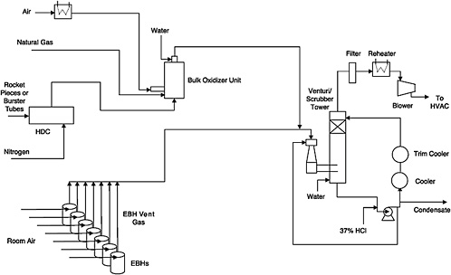
FIGURE 4-4 Flow diagram for OTE system. SOURCE: Adapted from Bechtel Parsons Blue Grass Team responses on May 2, 2005, to committee questions of April 25, 2005.
tubes are being processed in the HDC, since the latter do not produce a sufficient amount of hydrocarbons to sustain the required destruction temperature. The discharge stream from the bulk oxidizer will be cooled to 1200°F by injecting atomized process water into the top of the oxidizer unit.
The cooled discharge from the bulk oxidizer is then combined with vent gases from the EBH units and fed into the venturi/scrubber tower system, where it is scrubbed by a cool spray of scrubber solution. The EBH offgas contains hydrogen generated by caustic hydrolysis of aluminum parts of the rockets, but this offgas is diluted to below 25 percent of the lower flammable limit in individual EBHs and in the combined EBH offgas streams by adding air. When the hydrogen is combined with the bulk oxidizer offgas, its concentration is further reduced.
The venturi/scrubber tower system consists of a venturi, a scrubber tower with a surged bottom section, two 50 percent recirculation pumps and one spare, and two cascading coolers. The venturi uses acidic scrubbing water to remove ammonia and provide quick quenching (0.3 seconds) and prevent formation of dioxins and furans. The scrubbing water pH is controlled by addition of 37 weight percent HCl. Additional cooling of the gases to no more than 100°F is accomplished in the scrubber tower. The scrubber water is cooled in two cascading coolers; the first cooler uses 100°F cooling water as the cooling medium, while the second cooler uses 70°F chilled water. Excess scrubber water, created by condensation of water from the offgas stream, is sent to storage and subsequent processing.
The scrubber gases are then sent to an offgas filter to remove any particulate matter over 0.5 microns in size. The size limit for the particulate is under review. Gas from the filter is then reheated to 120°F in an electric heater to ensure a gas relative humidity of less than 55 percent and to prevent condensation before sending these gases through the induced draft blowers and into an exhaust duct to the carbon filter system for the MDB heating, ventilation, and air conditioning system.
Finding 4-8. Because the type of flameless bulk oxidizer unit to be used for the OTE system was not identified, it was not possible for the committee to assess the appropriateness of the OTE system for this application.
Recommendation 4-8. The bulk oxidizer unit design should be finalized as quickly as possible to ensure that all necessary supporting equipment is identified and that the MDB footprint can accommodate the resulting OTE system.
Finding 4-9. Particulates and condensate in the HDC offgas stream flowing to the bulk oxidizer may cause plugging, depending on the design of the unit. If plugging occurs, the bulk oxidizer may cause excessive plant downtime when processing rockets.
Recommendation 4-9. The allowable size range of particulates and concentration of condensate in gas flowing to the bulk oxidizer unit when processing rockets should be fully characterized to ensure that this unit achieves the high availability needed for successful plant operation.
Finding 4-10. The storage and treatment of scrubber condensate to which HCl has been added have not been specified.
Recommendation 4-10. The design for the handling of scrubber condensate must be carefully reviewed, since it is unclear at this time where this condensate, which may be acidic, will be sent.
Finding 4-11. The EBH offgas contains hydrogen from the hydrolysis of aluminum. This gas is planned to flow directly to the venturi/scrubber system. The treatment of offgases from the ENRs and energetics hydrolysate storage tanks had not been specified at the time this report was being prepared.
Recommendation 4-11. Treatment requirements for EBH, ENR, and energetics storage tank offgas streams should be determined as soon as possible since they may affect the size of the MDB and the OTE venturi/ scrubber system.


