
Appendix G
Tank Waste Retrieval Techniques and Experience at West Valley and Oak Ridge
This appendix provides more detailed discussions of tank waste retrieval techniques mentioned in Chapter III. It also elaborates on the experience with tank cleanup at the West Valley Demonstration Project in New York and the Oak Ridge National Laboratory in Tennessee, mentioned in Chapter III.
HYDRAULIC TECHNIQUES
By far the most popular techniques for mobilizing residual wastes involve the use of pressurized water. As with bulk sludge retrieval, the water is usually formed by reusing supernatant or some other internal recycle stream to reduce the amount of makeup water introduced into the system. One class of hydraulic devices is moved around the tank to wash radioactive material from the walls and top the tank bottom. Devices in this class include a rotating flusher nozzle using low-pressure water (<1,000 pounds per square inch [psi]) much as in a dishwasher, or a manually directed jet of moderate-pressure water (1,000 to 3,000 psi), which has been used to remove the more recalcitrant deposits in smaller areas. While the jet can remove materials that are unaffected by the rotating nozzle, it must be directed manually (through remote controls) at the area of concern. Hence, this technique is labor intensive. Moreover, because of the introduction of fluids, these techniques must be used carefully in tanks that are known or potential leakers to prevent additional release of radionuclides to the environment.
A second class of hydraulic device uses low-pressure water from sluicing jets to mobilize the solids present on the bottom of a tank after bulk waste retrieval or to wash the internal tank surfaces and collect the material around a transfer pump, a process similar to using a water hose to mobilize and corral debris on a driveway.
Each site has developed its version of hydraulic techniques for tank cleaning. The Savannah River Site has used rotary spray jets (Tank 16) and a water monitor to wash the internal surfaces of the tanks, a moderate-pressure water jet called the “water mouse” to break up solid deposits on the bottom of the tank, and a sluicing jet known as the “waterbrush.” It has also used a high-pressure jet (10,000 to 30,000 psi) called the Hydrolaser/hydrolance in Tank 19 to break up a 42-inch high by 30-inch diameter mound of zeolite. This technique is very effective for hard materials within a couple of meters of the nozzle but ineffective beyond this range. It should be noted that the solids resulting from breaking up zeolite deposits can be difficult to mobilize, collect, and transfer because they settle very quickly.
The Hanford Site has used a manually directed jet to wash internal tank surfaces and a sluicing technique that involves two directional nozzles. This system was used in Tanks C-106, and in Tank S-112. For Tank S-112 a new tool, called the Salt Mantis (also known as the Hydrolaser), involving a high-pressure water lance is being tested with promising results. The Salt Mantis can fit down a 10-inch riser and then unfold to form a large cross. The Mantis has two tires, one on each cross-beam of the cross, that are each hydraulically operated to manipulate the Mantis inside the tank. The long member of the cross provides stability when the water lance is working. The Mantis puts out a low-volume (6 gallons per minute [gpm]) of high-pressure water (variable between 2,000 and 35,000 psi) to break up the waste, which is then removed by sluicing. In a 10-hour demonstration test in Tank S-112, the Salt Mantis uncovered 30 percent of the tank bottom. One of the advantages of this tool is that is has a “low head” (i.e., does not provide a significant driving force to cause leaks). The Salt Mantis works best with approximately 1 foot of water that its high pressure jets can agitate the standing water and use it to break up the waste.
The Idaho site has used a device called the “washball” (see Figure G-1) in combination with directional nozzles that direct a relatively low-pressure (less than 100 psi) stream of water onto a vertical slice of the internal tank surfaces (walls, roof) above the waste to wash radioactive material onto the bottom of the tank. Figure G-2 shows the jets from the directional nozzles on the tank walls.
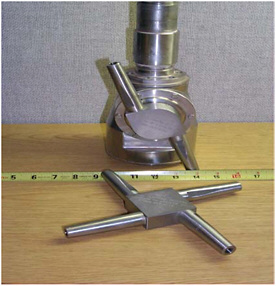
FIGURE G-1 Tank cleaning washball used at the Idaho site.
SOURCE: Lockie et al., 2005.

FIGURE G-2 High-pressure water jet used to clean the tank walls at the Idaho site. Note the horizontal cooling coils on the walls.
SOURCE: Lockie, 2005b.
VACUUM TECHNIQUES
For situations in which using significant amounts of water is not acceptable—for example, in tanks that have already leaked or are at risk of leaking—vacuum technologies in combination with small amounts of fluids are used. The Hanford Site has developed a vacuum retrieval device consisting of a vacuum head, a vacuum pump, a slurry vessel, and slurry transfer pumps. Air and water are added to assist in transferring the waste to another tank pneumatically. This device operates much like a steam carpet cleaner where the water is injected and almost immediately removed. This prevents any significant accumulation of water and thus reduces the potential for leaking water to the environment. Additionally, small amounts of high-pressure water can be introduced via a scarifier to dislodge waste and help suspend heavy particles so that they can be removed.1
The vacuum retrieval system has been used successfully in completing waste retrieval from Tanks C-202 and C-203 at Hanford. The heel volumes in Tank C-202 and C-203 are estimated at 19.6 and 18.5 cubic feet, respectively, in both cases meeting the Hanford Federal Facility Agreement and Consent Order retrieval criteria (limits of technology and less than 30 cubic feet). Hanford plans to use vacuum retrieval to retrieve residual waste and may use it for bulk waste retrieval in tanks where leakage becomes a problem.
MECHANICAL TECHNIQUES
Mechanical retrieval devices have been used for two purposes. First, they have been used to break up solid deposits. Such devices use remotely controlled grinding or scraping tools. The resulting particles can then be mobilized and collected for removal by a transfer pump using techniques described above. Such techniques can be very effective but the deposit must be accessible to the device and its use is labor intensive (Figure G-3).
The second purpose for using mechanical retrieval devices is to move wastes without having to introduce water into the tank. Examples of such devices are pushers that move waste to a transfer pump or move debris out of the way so the waste is amenable to hydraulic techniques or hooks or pincer claws that remove debris from the tank.
DEPLOYMENT TECHNOLOGIES
All physical techniques for retrieving residual wastes in tanks require some type of deployment technology of which there are three:
-
A jointed arm or mast that is installed through the tank riser and maneuvered to access various portions of the inside of a tank by human control;
-
A tethered vehicle that is normally connected via wires inserted through a tank riser or potentially electronically to a human controller; and
-
An autonomous robotic device programmed to adapt to the requirements at hand with minimal human inter-
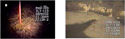
FIGURE G-3 Residual waste on the bottom of Tank S-112 after modified sluicing and saltcake dissolution. SOURCE: Barton, 2005a.
-
vention. Such a device may be powered by on-board rechargeable battery packs and an in-tank recharging station or by electrical cables inserted through a riser.
To date the dominant deployment technology for tools used to retrieve residual wastes has been mechanical arms. The most popular type of arm used at Department of Energy Sites (DOE) sites is a relatively simple mast inserted through a riser from which an arm containing one or two joints projects and some type of retrieval device extends. This technology has been used to deploy washing technologies such as the wash ball, water jets (see Figure G-3), vacuum devices, and mechanical devices and waste mobilization and collection technologies such as sluicing jets and water brooms. Mechanical arm technology has two main advantages: (1) it is a demonstrated and available technology, and (2) it can reach virtually any part of a less impeded (i.e., without cooling coils) tank. The disadvantages of this technology are that the lifting capacity of the arm across the necessary distances in underground tanks is limited, it requires detailed manual control by a human, and its operation can be impeded severely by some internal tank structures. Moreover use of these technologies for deploying tools is more time consuming than simply mixing and pumping because operating a remote arm in a cluttered environment can be tedious and demands concentration so operators have to be rotated periodically. However, the advantage of articulated arms is to access waste that cannot be accessed easily using centralized mixing systems.
Tethered vehicles have been used at the Oak Ridge National Laboratory, Savannah River, and Hanford Sites to deploy various tools to the bottom of underground tanks containing radioactive waste (Burks, 2005). The size of the tanks in which these devices have been tested or deployed varies from 5.7 – 644 m3 (1,500-170,000 gallons; Oak Ridge) to about 3,785 m3 (1 million gallons, Hanford and Savannah River). These are best envisioned as small tracked vehicles (crawlers). Such vehicles have deployed tools to wash tank internal surfaces (e.g., water jet), hydraulically or mechanically break up solid deposits (e.g., water mouse, scarifier), hydraulically mobilize and collect wastes (e.g., the “water brush” used at the Savannah River Site, or mechanically mobilize and collect waste by acting as a mini-bulldozer (see Figure G-4).
Tethered devices have two main advantages: (1) the ability to access tank surfaces that are inaccessible to mechanical arms, and (2) the ability to deploy relatively heavy tools to distant tank locations that are beyond the capabilities of mechanical arms. The disadvantages of in-tank tethered devices are similar to those for articulated arms: the need for detailed manual control by skilled humans, the need to rotate operators, the complications of maintaining the on-board electronics and sensors, and maneuvering their tethers in tanks having internal structures such as cooling coils. Deployment of autonomous retrieval technologies is beyond the current state of the art and is discussed further in the section on advanced technologies.

FIGURE G-4 Houdini™ in-tank crawler. SOURCE: RedZone Robotics.
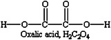
FIGURE G-5 Chemical composition of oxalic acid.
CHEMICAL TECHNOLOGIES FOR RESIDUAL WASTE RETRIEVAL
When physical technologies for retrieving residual waste have not been deemed sufficient, DOE has employed chemical technologies to remove remaining tank wastes. Tests performed in the late 1970s and early 1980s (Bradley and Hill, 1977; Hill, 1978; West, 1980) proved oxalic acid solutions to be the most effective reagent for dissolving sludge while not corroding the carbon steel tank. Oxalic acid (H2C2O4; see Figure G-5) is a reactive chelating agent and a weak acid (pKa1 = 1.2; pKa2 = 4.2).
Oxalic acid solutions dissolve some radioactive materials that are found in recalcitrant forms or difficult-to-access locations. Most of the resulting solution is readily retrievable by pumping. Oxalic acid treatment has been used in Tank 16 at the Savannah River Site and in Tank C-106 at Hanford. In both instances, oxalic acid allowed further retrieval of residual waste. Oxalic acid treatment was also applied to Tank 24 at the Savannah River Site which contained 37.9 m3 (10,000 gallons) of zeolite (used as an ion exchanger to separate cesium-137), but it proved ineffective in this application.
Previous Savannah River Site experience indicates that using oxalic acid can be effective at removing some residual wastes from tanks. However, Savannah River Site staff expressed reluctance to use oxalic acid extensively for the final stage of cleaning due to concerns about criticality, downstream processing, and cost.
Criticality Concerns Using Oxalic Acid
Since its interim report, the committee has received additional information from Savannah River Site staff about criticality concerns. The following is based on the information provided by the site (DOE-SRS, 2005e). According to the Savannah River Site staff, sludge heels after bulk waste removal may contain enough fissile mass,2 on average, to cause a criticality event. Savannah River Site staff could not share with the committee the exact amounts of fissile mass for reasons of homeland security. However, the staff told the committee that some tanks have uranium enriched to 60 to 70 percent. Safe storage in waste is achieved by diluents and neutron poisons. Bulk removal and water washing do not significantly affect the relative ratios of diluents and poisons to fissile material, but dissolution of a sludge heel with oxalic acid may cause the diluents and poisons to separate from the fissile material. The following sections describe information on solubility available in the literature, simulated waste dissolution tests, and actual waste dissolution tests that Savannah River Site staff provided in response to the committee’s request for the rationale on criticality concerns.
Karraker (1998) reviewed the available solubility data for uranium, plutonium, iron, and manganese in oxalic acid solutions, and concluded that the neutron poisons are considerably more soluble than plutonium, which could result in separation of some plutonium from the poison (Karraker, 1998). The specific chemical compound for each of the sludge components affects the relative rate of dissolution. Although solubility differences exist, the dissolution rates could affect the observed behavior with real waste. Relative reaction rates for the poisons are discussed in Adu-Wusu (2003). Actual rates relative to uranium and plutonium are not available.
One waste dissolution test with Tank 16 sludge at the Savannah River Site indicates that some portion of the plutonium could be highly insoluble, but sample sizes were too small to be conclusive (Bradley and Hill, 1977). A follow-up analysis for the extent of insoluble plutonium showed that about 30 percent of the plutonium remained insoluble after 99 percent of the bulk sludge was dissolved including the primary neutron poisons (Hill, 1978). Hobbs (2003) conducted laboratory oxalic acid dissolution testing on sludge from Savannah River Site Tank 8 to evaluate the downstream impacts. The sludge contained high levels of sodium oxalate although the test data were inconclusive regarding any increased leaching of plutonium and uranium.
Although not directly applicable to Savannah River Site waste, an example of laboratory tests with Hanford waste show that 5 to 20 percent of the total alpha-emitting isotopes are dissolved with oxalic acid. Up to 50 percent of the iron and 80 percent of the manganese dissolved in the same sample (Bechtold et al., 2003). The data from samples of waste remaining after each acid wash cycle during Tank 16 heel dissolution with oxalic acid provide enough information to identify a relative change in plutonium content with poisons. These tests showed that plutonium appeared to decrease compared to iron relative to the initial sludge composition, but remained more or less constant with each subsequent acid strike (Bradley and Hill, 1977; West, 1980, Table 6).
As DOE recognizes, the available data are inconclusive with regard to the potential for criticality during oxalic acid dissolution because the bulk of the material, including the fissile material, may be removed before the ratio of fissile material to poison falls below safe storage limits. Savannah River Site staff told the committee that each tank heel needs
to be evaluated before attempting dissolution with oxalic acid to determine whether any criticality potential exists and how to mitigate the risk. The committee has not seen any additional calculations regarding the criticality issue and cannot determine whether the concern is real, the committee recommends that DOE investigates the matter further (see Chapter IX).
Downstream Problems Using Oxalic Acid
According to DOE, there are additional downstream complications when using oxalic acid due to the large amounts of acid needed to neutralize the waste and to dissolve the residual sludge (e.g., approximately 276 m3 [73,000 gallons] of 4 weight percent for Tank 16). The process flowsheet for the use of oxalic acid in tank cleaning is estimated to add about 26,000 to 38,000 kg of sodium oxalate per 19 m3 (5,000 gallons) of sludge residual removed. These oxalates eventually are processed in the Savannah River Site evaporator system and will create some operational problems based on past experience. For example, in the 2H evaporator it was found that the crystalline structure of the sodium aluminum silicate (which was formed by mixing high-silica streams with high-aluminum streams) has an affinity for uranium but not for any of the neutron poisons, so there was a selective concentration of uranium in the evaporator that raised some criticality issues. If it is added to the sludge before washing, oxalic acid goes to the evaporator and may precipitate in the feed tank. If oxalic acid is added to the salt tank it may precipitate and form a hard salt layer that would require a lot of water to remove.
Other problems cited as part of downstream concerns with oxalic acid are the following:
-
Foaming during evaporation. Savannah River Site staff stated that the addition of oxalic acid has been observed to cause foaming during evaporation of recycle streams to reduce volume. Such foaming compromises the function of the evaporator.
-
DWPF off-gas flammability. To prevent the possibility of combustion or explosions in Defense Waste Processing Facility (DWPF) off-gas processing equipment, the amount of organic material fed to the DWPF is limited. Substantial use of oxalic acid could lead to these limits being exceeded.
Melter performance in the presence of oxalates does not seem to be a concern at the site. The melter can tolerate considerable amounts of oxalate in the feed (spent oxalic acid wash from up to 10 to 15 tanks).
Cost Of Using Oxalic Acid
DOE’s estimate for oxalic acid washing in 1999 was $1,050,000 per tank, including disposal costs at the Savannah River Site. DOE concluded that, for the F Area Tank Farm, oxalic acid washing of the 10 remaining tanks would add approximately $10,500,000. DOE expects results for individual tanks in the H Area Tank Farm to be similar in terms of additional costs (USNRC, 1999).3 A 2005 study estimates the cost of using oxalic acid to be $15,000,000 each for Tanks 18 and 19, attributing additional costs to the need to retrofit the two tanks completely (remove old equipment and purchase and install new equipment, including a chemical addition system) 4 (Gilbreath, 2005). Cost estimates would be lower for other tanks if the oxalic acid addition were performed immediately after waste residual removal and before the tank is isolated for closure. According to Savannah River Site staff, additional costs are due to the nuclear criticality safety and evaluation reports that DOE would have to do on a tank-by-tank basis to show the effect of oxalic acid on the neutron poisons.
DOE Plans to Use Oxalic Acid in the Future
DOE has indicated it is planning to use oxalic acid as a final cleaning step at the Savannah River Site on a tank-by-tank basis, taking into account the factors listed above (DOE-SRS, 2005d). The site is interested in chemical cleaning technologies. A team was formed in December 2005 at the Savannah River Site to evaluate the use of nitric acid and its application to sludge removal in Savannah River Site waste tanks. However, the committee believes that the site is lacking a strong impetus for research and development at this time (DOE-SRS, 2005e). In Chapter IX, the committee provides findings and recommendations on research and development needs in chemical cleaning.
Hanford is not planning to use oxalic acid in the future. According to DOE, oxalic acid was only modestly successful in breaking the hard waste residual in Tank C-106 and was used in conjunction with other hydraulic retrieval technology. Barton reports that three acid batches and one sluicing operation on tank C-106 removed more than two-thirds of the waste. The last three oxalic acid batches did not react further with the waste (based on pH readings). Water sluicing was able to mobilize part of this residual waste and move it toward the transfer pump (Barton, 2005b).
Hanford’s tank wastes were formed by many different chemical processes (Bismuth Phosphate Process, REDOX
Process, PUREX Process) and waste separations techniques, each contributing a different mix of chemicals to the tanks. As a result, any chemical technique used for hard heel removal has to be tailored to the chemical characteristics (origin) of the heel in each tank. The chemical must (1) break up the hard heel matrix to enable removal by sluicing, (2) not add substantial new chemical bulk to be removed in pretreatment, and (3) not put the actinides and strontium-90 in soluble forms (which would defeat solids-liquids separations in the ultrafiltration system) to avoid the same criticality issues identified by Savannah River Site staff.
In the case of the oxalic acid used on Tank C-106, oxalate solids were formed that now must be removed by ultrafiltration in the Waste Treatment Plant. The ultrafiltration system is a bottleneck in the Waste Treatment Plant due to the filters being used for several operations (e.g., sludge washing, oxidative leaching). Systemically adding chemical burden to the ultrafiltration system could impact the feed rates to the Waste Treatment Plant high-level waste melters and low-level waste melters. Dissolution of additional strontium and transuranic waste could also result in more wastes that require additional pretreatment to ensure that immobilized low-activity waste glass meets regulatory limits and ALARA (as low as reasonably achievable) package handling requirements. These additional pretreatment steps will slow the overall production of the waste treatment plant, resulting in additional years of operation of the combined system.
Accordingly, Hanford’s waste retrieval staff is more interested in mechanical and high-pressure hydraulic techniques such as the plow blade on the Mobile Retrieval System (MRS) and the high-pressure water lance on the Salt Mantis. Both robotic techniques allow DOE to break up hard heel materials to perform more complete retrievals without further complicating the tank farm and Waste Treatment Plant chemistry (Hewitt, 2005a). Idaho is not planning to use oxalic acid because its tanks do not have sludge to remove.
TECHNOLOGY ADVANCES FOR MECHANICAL RESIDUAL WASTE RETRIEVAL
Pulsating Mixer Pump Technology
DOE is considering the use of the Power Fluidic TechnologyTM developed by AEA Technology and a similar Russian Pulsating Mixer Pump Technique for bulk waste retrieval at the Hanford and the Savannah River Sites (Murray, 2005). This technology involves using two or more nozzles in a tank to establish a “back-and-forth” motion of the sludge and a vacuum induced by fluid flow through a “jet pump system,” as shown in Figure G-6.
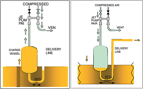
FIGURE G-6 Key components of a pulse jet system. SOURCE: AEATES, 2005a.
This technology does not have any mechanical devices inside the tank and is claimed to use water more efficiently. Fluidic technology can be used for bulk waste as well as residual waste retrieval and for mixing the grout with waste residuals that cannot be further removed. However, its effectiveness on waste in tanks with vertical cooling coils is uncertain as with other technologies.
Hanford tested a prototype using this technology in a full-scale cold test facility, and determined that the complex air and fluid controls and air handling systems would result in significant maintenance and ALARA concerns for operations in the single-shell tank farm system. No further deployment of fluidic technology for waste retrieval from single-shell tanks is planned. Use of fluid jets for mixing grout with waste residuals is still under consideration.
Hanford Mobile Retrieval System
The Mobile Retrieval System consists of a vacuum retrieval device mounted on a mechanical arm (mast) combined with a remotely operated in-tank vehicle (ITV) (see Figure G-7).
The ITV is equipped with a plow blade and a water jet used to move waste within the range of the vacuum device. The plow is used to move or break up the waste. The vacuum system uses a small amount of water to mobilize the waste as it is sucked up by the vacuum. The waste is collected in the slurry vessel where it is then pumped from the tank. The articulated mast is fitted with a vacuum head, vacuum pump, slurry vessel, and slurry transfer pump (the same type of vacuum retrieval apparatus that was successfully used to remove sludge from Tanks C-203 and C-202).
The Mobile Retrieval System (MRS) removes waste from a single-shell tank by using raw water to mobilize the sludge in the tank and remove it with a vacuum device. Recycled supernatant is then used to transport the waste to the double-shell receiving tank. The recycle loop may include skid-mounted equipment to dewater the recycle stream to reduce water usage. As a result of being composed of devices already used in other tank retrievals, the MRS represents an incremental improvement over previous retrieval technology. Like the Salt Mantis, the MRS has a low head since there is little or no standing water in the tank. Therefore, these tools are appropriate for tanks that have a high risk of leakage. The mobile retrieval system will be deployed for the first time in Tank C-101.
Delivery Tools
Essentially all of the techniques for retrieving residual wastes in tanks described in this chapter must be deployed
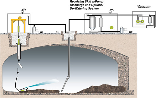
FIGURE G-7 Mobile Retrieval System. SOURCE: Gasper: 2005.
by delivery tools, such as multijoined mechanical arms and in-tank tracked and tethered vehicles. DOE has developed advanced mechanical arms having multiple joints and improved guidance capabilities. The most prominent example of this is the Light-Duty Utility Arm (LDUA) and its modified version (MLDUA). In September 1996, the LDUA’s stereo viewing systems and gripping capacities were demonstrated successfully in Hanford Tank C-106. The LDUA was deployed at the Idaho site for approximately two months in early 1999 to inspect and sample Tank WM-188, and later in the year to inspect and sample Tanks WM-182 and WM-183. The MLDUA was used at Oak Ridge National Laboratory (ORNL) from June 1997 through September 2000 to retrieve waste from two tanks with 161 m3 (42,500 gallon) capacity and five tanks with 644 m3 (170,000 gallon) capacity (Glassell et al., 2001). These demonstrations yielded mixed success: The LDUA used at Idaho was able to deploy multiple tools within its reachable workspace but had significant downtime due to hardware failures. Since this demonstration, DOE sites have used simpler mechanical arms for residual waste retrieval as described previously. It is not known whether the need to retrieve wastes from more complicated tanks will lead to further development of the LDUA to improve its reliability. The MLDUA used at ORNL had almost no hardware failures over the time (3 years and 4 months) it was deployed (Glassell et al., 2001).
As discussed earlier, several tracked tethered vehicles have been developed in the DOE complex to operate inside a tank in limited amounts (less than 10 cm deep) of sludge or liquid. Some of these vehicles (Houdini™, ESG/LATA) are collapsed to fit through a 61 cm- (24 inch) diameter riser and then expanded to a 1.5 by 1.5 meters working platform; others vehicles are fixed frame and must fit through the riser openings. Some of the crawlers are available commercially (Houdini™, ARD). The committee did not find evidence of any foreseeable dramatic improvements in crawler technology, but incremental engineering improvements are likely to continue (see Chapter IX).
GENERAL WASTE RETRIEVAL ISSUES
Previous sections have alluded to future difficulties that can be expected when retrieving waste from DOE’s “complicated” tanks. The following sections describe some of the important complications that are anticipated.
Recalcitrant Waste Deposits
Waste may be encrusted on internal tank surfaces or structures in a semidry form, or it can agglomerate in chemical forms that resist physical removal technologies. These recalcitrant waste deposits must be mobilized before they can be collected and removed from the tanks.
One of the most common types of recalcitrant waste deposit is composed of inorganic zeolite ion-exchange material that has reacted with tank chemical contents to yield sodium and calcium aluminosilicates that form a solid deposit (see Figure G-8). Zeolites were used to separate
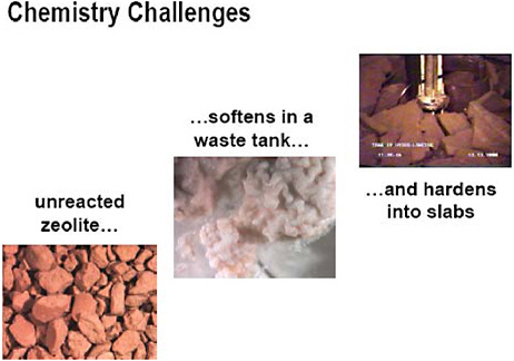
FIGURE G-8 Zeolite deposits can be difficult to remove because the fine particles formed when the slabs of zeolite are broken up by waste retrieval tools settle very quickly at the bottom of the tank. SOURCE: Caldwell, 2005a.
cesium-137 from the waste and are potentially important because they contain significant amounts of this radionuclide. The Savannah River Site had 11 tanks containing zeolite deposits, of which 2 (Tanks 18 and 19) that do not contain cooling coils have recently been cleaned. Eight of the remaining nine zeolite tanks have coils (see Appendix F).
Zeolite compounds are recalcitrant for two reasons. First, they are difficult to dissolve. Based on experience at the Savannah River Site and Hanford, chemical cleaning using oxalic acid is moderately successful at best. Savannah River is also considering using nitric or hydrofluoric acid to dissolve the zeolite particles but these two acids are very corrosive on carbon steel tanks. Second, although the deposits can be disaggregated into sand-like particles using mechanical techniques, the particles are difficult to keep in suspension for recovery with transfer pumps. Savannah River Site has considered the use of in-tank vehicles (such as the mini-bulldozer used in Hanford) to corral the zeolites, but anything with a tether makes deployment in tanks with coils very challenging. Savannah River Site staff has requested the help of DOE’s Office of Cleanup Technologies (EM-21) for research and development on zeolite removal.
Hanford Site staff noticed hardened saltcake deposits in Tanks S-112 and S-102. Waste retrieval in these two tanks is being pursued using high-pressure devices such as the Hydrolaser/hydrolance (in S-112) and the Salt Mantis (in S-102).
Waste Accessibility
To remediate a tank, the waste has to be accessible to waste removal tools. One of the main challenges of waste removal is the number of physical obstacles to the waste and other issues related to tank design that complicate waste retrieval operations. The following is a list of waste retrieval challenges due to tank design features or physical obstacles that impede access to the waste or due to tank integrity concerns that limit the choice of waste retrieval tools. This list was developed by the Tanks Focus Area in 2002 for the Savannah River Site, but many of the challenges apply to the Hanford Site and a few to Idaho National Laboratory as well.
Waste retrieval challenges identified by the Tanks Focus Area (adapted from Saldivar, 2002) include the following:
-
Horizontal cooling coils (Savannah River Site and Idaho National Laboratory)
-
Vertical cooling coils (Savannah River Site only)
-
Tank integrity limiting the choice of retrieval tools (Hanford Site)
-
High-level Waste environment on tank top and in surrounding area
-
Tank bottoms located 45 to 50 feet below ground surface
-
Contamination containment for potentially leaking equipment
-
Nonsymmetrical riser positions
-
Confined spaces (Savannah River Site only)
-
Limited openings into the primary tank and annulus space—no larger than 24 inches in diameter (Savannah River Site only; see Figure G-9)
-
Removal of waste from the ventilation duct at the bottom of the annulus space (Savannah River Site only)
-
High radiation rates in tank and at riser openings
-
Tank top loading is limited
-
All transfers out of the tanks are from one riser location
-
Tank support columns produce shadowing effects (all sites)
Of these, the most difficult to overcome is likely to be the vertical cooling coils in Savannah River Site tanks, which severely impede the ability to maneuver water jets, mechanical arms, and in-tank vehicles to access the waste.
The Hanford tanks, although they do not have cooling coils, have some internal obstructions such as the air-lift circulators used to stir and suspend the sludge in high-heat tanks. The designs vary, with some welded to the floor with “guy wire” supports and others suspended from risers at the top of the tanks. A single tank can contain as many as 22 air-lift circulators. The following tanks have air-lift circulators installed:
-
15 single-shell tanks in SX Farm
-
6 single-shell tanks in A Farm
-
4 single-shell tanks in AX Farm
-
2 double-shell tanks in AY Farm
-
2 double-shell tanks in AZ Farm
According to DOE, the circulators in Tank AZ-101 (see Figure G-10) are probably the most complex in the Hanford tank farms.
In-Tank Debris
Most underground storage tanks, especially at the Hanford and Savannah River Site contain objects labeled as debris. These can include failed pumps, tapes for measuring waste depth, instrument trees, sluicers, hoses, and miscellaneous items. Some items have been left in place (e.g., suspended from the top of the tank); while others (such as waste surface measuring tapes) have been dropped into the tanks. In some cases, miscellaneous materials were added to the tanks (generally during the 1960s and 1970s) as a way to dispose of them. Such debris can interfere with bulk or residual waste retrieval by impeding the flow of water necessary to mobilize and collect wastes at the location of a transfer pump. Some of the in-tank debris at the Hanford Site includes the following:
-
Six single-shell tanks that were past leakers have as much as 95,000 kg of diatomaceous earth per tank that was added to absorb liquids;


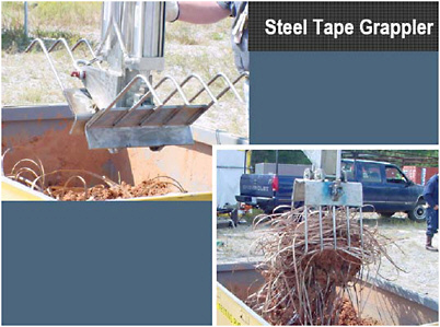
FIGURE G-11 Steel tape grappling device developed at the Savannah River Site. SOURCE: DOE-SRS, 2005g.
-
At least one single-shell tank contains approximately 57,000 kg of Portland cement, which was added to bind liquids;
-
One single-shell tank contains 7 m3 of organic ion-exchange resin that was disposed of in the tank;
-
One single-shell tank contains 16 plastic bottles (3 inches in diameter x 54 inches long) containing uranium solutions that were disposed of in the tanks;5 and
-
One single-shell tank contains six cask loads of experimental fuel elements, shroud tubes, and samarium ceramic balls that were disposed of in the tank.
To address the issue of in-tank debris, DOE has developed techniques (e.g., grappling devices to retrieve tape measures (see Figure G-11) that can remove some of the debris or move the debris to different locations to allow the underlying waste to be retrieved. Neither the Savannah River Site nor the Hanford Site identifies in-tank debris as a major obstacle to waste retrieval (DOE-RL, 2005; DOE-SRS, 2005d). If heel retrieval systems that use vehicles or mobile in-tank systems are deployed, debris may become a problem even if these systems are capable of removing this debris or moving it around the tanks.
Residual Waste in Pipelines and Ancillary Equipment
The large underground storage tanks that are the primary focus of retrieval are interconnected by myriad pipelines and ancillary equipment, such as small underground storage tanks, pumps; valve boxes used to transfer tank wastes among the large tanks, and other hardware used in waste retrieval operations (see Figure G-12). As a consequence, to varying degrees, these pipelines and ancillary equipment contain tank waste that will likely have to be removed to the maximum extent practical. The closure of pipelines and ancillary equipment has been considered part of the draft Section 3116 waste determination at the Idaho National Laboratory (INL; DOE-ID, 2005a). At the Savannah River Site pipelines and ancillary equipment will be addressed in the tank farm closure determination. Hanford staff recently produced a study on plugged and abandoned pipelines (Lambert, 2005).
As part of routine practice, the majority of pipelines and ancillary equipment is flushed with nonradioactive water after use so the remaining waste is expected to contain amounts of radionuclides that are small relative to what is being left in the tanks. As an example, at the Idaho National Laboratory (which has the most compact array of tanks) there are about 2 miles of pipelines associated with the tanks containing an estimated 30 Ci in about 15 kg of waste.
There are challenges associated with the pipelines, foremost among which is the fact that a few of the pipelines plugged during use so that they could not be flushed to remove most of the residual radionuclides. This is especially the case at Hanford where an estimated 100 pipelines are plugged; they contain about 900 liters (232 gallons) of waste (Lambert, 2005). A lesser problem is that records of a limited number of pipelines may never have existed or have been lost during the intervening decades. Nondestructive methods
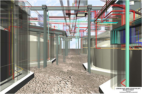
FIGURE G-12 Computer-generated image of underground pipelines connecting the tanks at Idaho National Laboratory. Similar underground structures are present at the other two sites. SOURCE: Lockie et al., 2005.
such as ground-penetrating radar may be used to locate the pipelines (NRC, 2000e; 2001b).
As a result of the relatively small amount of radioactive material believed to be in the pipelines and ancillary equipment, and because some of this system is still in use, DOE has accorded characterization and remediation planning a low priority and a formal decision process has not yet been initiated. Information obtained by the committee as a result of site visits and conference calls indicates that DOE is inclined to propose that most pipelines and ancillary equipment be flushed and grouted in situ while considering exhumation of plugged pipelines where necessary (Harbour et. al. 2004; Schaus, 2005). The Savannah River and Hanford Sites have both demonstrated grouting of pipelines (Harbour, 2000). Savannah River Site staff has demonstrated this ability on “non-tank farm” underground lines that contain relatively low (if any) amounts of contamination. Additional vents had to be installed on some of these lines to obtain proper flow of grout (this is impractical in the tank farms because of the relative depth of transfer lines, radiation rates to install vents, and difficulty in even reaching some of these locations due to obstructions). Harbour (2005) demonstrated that with proper grout flow characteristics and “vent and delivery hose in one,” grouting of lines over long distances is possible. This has not been demonstrated practically in Savannah River Site tank farms to date. Experience with pipeline plugging and unplugging from Russian Nuclear Defense Material production sites has also been published (Florida International University, 2001). Other technology reports on pipeline locating, unplugging, and cutting technologies were published as Innovative Technologies Summary Reports within DOE’s former Office of Science and Technology (ITSR, 1999a, 1999b, 1999c, 1999d, 1999e). The Tanks Focus Area also sponsored several projects on waste transfer line plugging prevention and unplugging methods involving chemical cleaning, pressure cycling, or vibration (e.g., DOE-TFA, 2000b, Welch, 2001).
Leaks to the Environment
To varying degrees, all three DOE sites have inadvertently released wastes contained in the tanks into the environment. At Hanford the releases are substantial and primarily the result of leakage from the single-shell tanks. At the Idaho
site, leaks to the environment were primarily the result of spills during tank transfers between reprocessing facilities and of tank and valve failures within the tank farms. At the Savannah River Site, the only leak to the environment is due to a crack in Tank 16 that leaked waste into the annulus pan. Such releases raise two issues: (1) the degree of retrieval from the tanks to be required given the context provided by the amount of radionuclides in the immediately surrounding environment, and (2) application of, removal to the “maxi-mum extent practical” to leaked radionuclides.
Regarding the first issue, the context provided by leaked radionuclides is one factor to be considered in determining whether radionuclides have been removed to the maximum extent practical. This issue is discussed further in Chapter X. Regarding the second issue, DOE has stated that it intends to address the remediation of radioactive material leaked from tanks using a Comprehensive Environmental Response, Compensation, and Liability Act (CERCLA) process.
SITE-SPECIFIC ISSUES
In addition to the general issues, a number of site-specific issues may limit the extent to which wastes can be retrieved, as discussed in the following section.
Savannah River Site
Retrieval at the Savannah River Site is favored by the fact that the integrity of the tanks is good with only one known minor leak to the environment (from Tank 16). High retrieval efficiencies obtained in Tanks 16, 17, and 20 may not be matched in the future because of site-specific conditions, as discussed below.
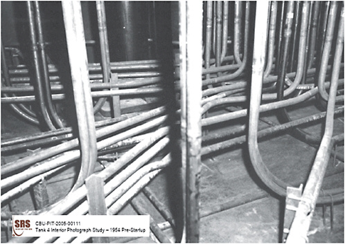
Waste Retrieval from Tanks with Vertical Cooling Coils
Among the 51 tanks, 43 contain a “forest” of vertical cooling coils (see Figure G-13). The coils in these tanks can impede conventional bulk retrieval technologies by creating numerous hydraulic ”shadowed” zones where waste can settle, as well as providing numerous additional surfaces to which waste deposits can adhere. The coils also impede physical residual retrieval technologies because they hinder the use of tools deployed on mechanical arms or tethered devices.
Chemical mobilization of waste residuals was successfully applied in a tank with cooling coils at the Savannah River Site (Tank 16). Tank 16 contained at least 265 m3 (70,000 gallons) of sludge that were sent directly to this tank from H Canyon during the late 1950s and early 1960s. Minimal salt formed on the “cool” areas of the tank and where the supernate flowed into the annulus pan (after repeated evaporation via the annulus ventilation system, the supernate eventually dried and left behind a salt residue). Tank 16 was subjected to chemical cleaning with oxalic acid. DOE reports that bulk waste removal and spray water washing removed 97.98 percent of radioactivity, and oxalic acid wash and rinse removed 99.98 percent of radioactivity in the tank (DOE-SRS, 2002).
As previously mentioned, DOE is in the initial stages of bulk retrieval of waste from a tank containing sludge and cooling coils (Tank 5). This effort should provide valuable information related to the effectiveness of available bulk retrieval technologies from a”complicated” tank and submersible mixer pumps. The increased effort required to retrieve sludge and the complications imposed by the vertical cooling coils make it more likely that additional retrieval measures will be required for such tanks to obtain an acceptably small heel. Such measures may include the need to use chemical cleaning methods or new physical methods for retrieving tank residuals.
As DOE acknowledges, Tank 11 will be particularly challenging to clean because it has 76 m3 (20,000 gallons) of high-activity sludge and vertical cooling coils. DOE is considering multiple retrieval tools for this tank. One of them is the Power FluidicsTM AEA Technology, which could also be used in combination with oxalic acid (DOE- SRS, 2005d).
The committee asked DOE whether it was possible to cut or bend the coils to improve accessibility to the waste. The committee agrees with DOE that cutting the coils is not a practical solution because the coil debris would have to be disposed in situ due to the limited riser accessibility. There are about 4 miles of coils per tank and cutting them or bending them would entail high doses to workers. Similarly, increasing the size of the risers to remove the coils would also involve high workers doses. Finally, because the coils are attached to the tank top and bottom, any force on the coils to cut or bend them would impose a stress on the tank structure. It is worth noting that Savannah River Site staff has bent (albeit very slightly) the coils in Tank 5 to introduce some of the waste removal equipment.
Retrieval of Waste in Tank Annuli
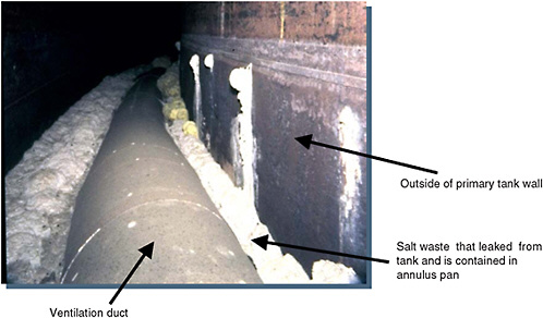
While only a very small amount of tank waste has leaked to the environment at the Savannah River Site, larger amounts have leaked from the primary containment into the annulus. Four Savannah River Site tanks are known to have waste accumulation in the annulus: Tank 9, Tank 14 (both with about 10-12 inches of salt waste in the annulus), and Tanks 10 and 16 (both with about 2 inches of salt waste in the annulus).
A photo of such waste deposits is shown in Figure G-14). It is not yet resolved whether such waste deposits will require retrieval, in part because the amount and composition of the waste in the annuli is not fully characterized.
Savannah River Site staff estimate that there are about 400,000 Ci of cesium in all the annuli (value extrapolated for all tanks based on inches of deposits observed). Most of the deposits in the annuli are believed to be salt waste from
supernatant seepage though small leaks. If waste is to be removed from the annulus, the general approach would be to add hot water and possibly steam to the annular space, allow the water to sit for roughly two weeks to dissolve residual salt waste, and then transfer the resulting salt solution to the primary waste tank. A combination of sampling and visual inspection would then be used to monitor and verify the progress of the cleaning effort (Badheka and Elraheb, 2004, p. 5).
While these methods should work on highly soluble salt deposits, they did not work when Tank 16 underwent annulus cleaning (DOE-SRS, 2005g, and references therein). During the leak investigation, the outside of the tank’s primary wall was cleaned using a sand-blasting technique. The silicates in the sand reacted with sodium and aluminum in the waste and formed sodium aluminum silicates which did not dissolve with hot water and agitation. DOE is considering using steam jets, agitation, and/or chemical cleaning to mobilize this waste in the annulus of Tank 16.
If waste deposits do not dissolve with hot water and steam, technology to retrieve such deposits is, at best, developmental, or, at worst, nonexistent. Development of a practical technology to clean the annuli is complicated because of very limited access to the annuli surrounding the tanks and very poor access to the ventilation ducts. Given that the annulus is a confined area with one less barrier to protect the environment from a potential release, the issue of waste retrieval needs serious consideration. DOE describes techniques for annulus cleaning in its “Heel Removal and Annulus Cleaning Technology Development Suspension Plan” (Cantrell, 2004), but the site acknowledges that techniques for annulus cleaning “need further development.” (DOE-SRS, 2005g).
Hanford
Retrieving waste from Hanford tanks could be easier than from Savannah River Site tanks for two reasons. First, Hanford tanks do not contain cooling coils. Heat was removed by evaporation and in some of the hottest tanks, the waste boiled off water at the rate of 114 to 151 liters per minute (30 to 40 gallons per minute). That water was condensed and returned to the tank for cooling. Unimpeded access to the tanks means that delivery tools for mobilizing, collecting, and removing residual waste can be brought to bear with much greater effect. In some cases however, the Hanford single-shell tanks contain failed equipment, thermocouples, metal tapes, and some equipment with air-lift circulation devices that may prevent unobstructed access to the waste. Second, the bottom of Hanford tanks is downwardly concave (like a dish), which makes it much easier to collect the residual waste in a small area to be pumped from the tank.
The foregoing notwithstanding, the Hanford Site does face two major waste retrieval issues. First, retrieval techniques must be compatible with corroding carbon steel single-shell tanks. According to DOE, 67 of the 149 single-shell tanks are known or suspected to have leaked as much as 3,785 m3 (1 million gallons) of waste and between 0.45 million and 1.8 million Ci to the subsurface environment beneath the tanks (see Chapter II). The problem of leaks has been managed so far by transferring liquid waste from the single-shell tanks to the double-shell tanks and leaving in the single-shell tanks just saltcake and sludge in the single-shell tanks. However, as mentioned previously, waste mobilization technologies involve the introduction of water or recycled liquids to mobilize residual waste. Reintroducing fluids into these tanks has the potential to release waste to the environment as at Savannah River. The second issue is that Hanford wastes are the result of multiple reprocessing technologies (i.e., Bismuth Phosphate, REDOX, PUREX) and chemical separations processes that resulted in significant tank-to-tank differences in waste chemistry, which must be factored into the retrieval techniques used. High phosphate wastes, in particular, create potential filtration and pipe plugging issues. Furthermore, as Hanford progresses in its waste processing campaign, it may face tank space challenges similar to those at Savannah River.
DOE has developed retrieval devices that use small amounts of water (see vacuum retrieval and Mobile Retrieval System earlier) in the hope of preventing leaks or reducing the amount of waste leaked to the environment. DOE has also developed devices such as the high-resolution resistivity leak detectors that can detect water entering the unsaturated soil beneath the tanks and allow DOE to cease retrieval before large amounts of waste are released (Barton, 2005c). However, the success of these devices in practice remains to be determined.
Idaho National Laboratory
The Idaho site has 11 underground tanks containing liquid sodium-bearing waste and 6 bins of calcined high-level waste solids.
Contaminated Sand Pads
Nine of the eleven tanks at the Idaho National Laboratory were built on a layer of commercial-grade sand that is 6 inches in depth at the circumference of the tank and 2 inches in depth at the tank center, which serves to cushion the tank bottom from an underlying concrete slab. This volume contains approximately 41,400 kg of sand (assumed density, 1.75 g/cc). The sand pads beneath two of the nine tanks (WM-185 and WM-187) contain radioactive material due to accidental releases into the surrounding vaults in March 1962 (Latchum et al., 1962). Before and after these releases, water from precipitation, spring runoff, and irrigation leaked into the vault areas and provided the mechanism to flush some radionuclides from the sand. The residual

FIGURE G-15 Interior of the Idaho National Laboratory Tank WM-183 before (left) and after (right) waste retrieval. SOURCE: DOE-ID, 2005a, Figures 11 and 12, pp. 29-30.
inventory predicted for 2012 is based on 38 such “flushing” events when water infiltrated the vault from leaks in the tank or vault roof and was then jetted out of tank vaults.
DOE estimates that the total radioactivity at closure is approximately 21,993 Ci (814 TBq), assuming that the four tanks remaining to be cleaned contain the same number of curies as Tank WM-182, which is the tank with the greatest residual contamination among those that have been cleaned (see Figure G-15). The sand pads contain approximately 30 percent of the activity at closure (6,598 Ci, 244 TBq), and the tanks contain approximately 70 percent of the residual curies (15,395 Ci, 570 TBq) in the fine layer of solids that is distributed unevenly over the bottom of the 300,000-gallon tanks. The piping contains about 0.12 percent of the activity (approximately 30 Ci, 1.1 TBq). Both the U.S. Nuclear Regulatory Commission (USNRC) and the State of Idaho commented that there is significant uncertainty about the inventory of the sand pads and recommended that DOE measure or better estimate the contaminated sand pad radionuclide inventories (Trever, 2006; USNRC, 2006). Neither DOE nor the committee has identified practical means to measure the inventory or to remove additional radioactivity from the sand pads.
Retrieval of Calcined Waste from Bins
Retrieval of calcine waste at the Idaho National Laboratory is very different from tank waste retrieval. As described in Chapter II, most reprocessing waste at the Idaho site was converted to a fine granular powder (calcine) by high-temperature heating. The calcine was transferred pneumatically to groups of stainless steel silos (bin sets) for storage pending final disposition. DOE’s plans call for the calcine to be retrieved from the bins, packaged, and shipped off-site to a high-level waste repository by December 31, 2035 (DOE-ID, 2002). However, these plans depend on the opening of a high-level waste geologic repository and on meeting the waste acceptance criteria for such a repository (potentially at Yucca Mountain, Nevada, but no license has been issued to date).
DOE proposes that the calcine be retrieved by reversing the process by which it was emplaced: vacuuming it from the bins through the risers. The committee viewed a video tape of simulated calcine retrieval by vacuuming which showed that the simulant was readily retrievable by this means: any caked calcine was readily dislodged by physical contact with the vacuum head, and the calcine could be transported pneumatically over significant distances (650 feet with vertical elevation changes) to processing facilities (Patterson, 2005). A cold demonstration in September 2005 by AEA Technology confirmed that solid deposits of the simulated calcine could be broken up using light mechanical impact with the retrieval nozzle. AEA Technology also simulated the retrieval of calcine exposed to various humidity levels up to 100 percent with similar success (AEATES, 2005b).6 According to DOE, vacuum retrieval will remove more than 99 percent of the calcine (DOE-ID, 2002). Work in progress on calcine retrieval in cooperation with AEA Technology includes optimizing the tip of the vacuuming nozzle to mobilize compacted calcine deposits as well as optimizing the control systems to minimize worker fatigue during vacuuming.
However, whether the actual calcine will behave like the simulant after residing in the bins is for several decades
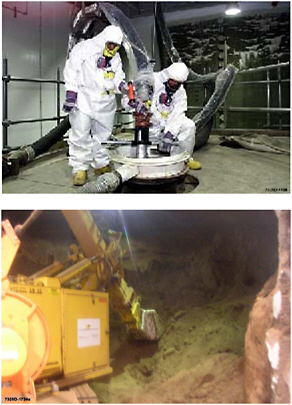
FIGURE G-16 Pneumatic (vacuum) retrieval from the top of Silo 3 at the Fernald facility in Ohio (left) and mechanical retrieval tool (the Excavator) operating from an opening in the wall of the silo (right). The wall of the Silo is visible at the right border of the frame. SOURCES: Left: www.nukeworker.com; right: Beckman, 2006.
uncertain. Information related to the effectiveness of this bulk retrieval technique, techniques for retrieval of residual calcine, and disposition of the emptied bins has not yet been developed. Moreover, the geometry of the bins and the configuration of the risers in the bins may also decrease the effectiveness of the vacuuming method (see Chapter II).
Waste retrieval experience for Silo 3 at DOE’s Fernald site shows how retrieval of calcine can be challenging. Silo 3 is a concrete domed silo 27 m (80 feet) in diameter and about 10 m (33 feet) above ground level. Five man-ways on the dome of the silo have an internal diameter of approximately 51 cm (20 inches). Silo 3 contained an estimated 3,890 m3 of finely powdered metal oxides from uranium recovery operations. Raffinate streams from solvent extraction were processed for storage through calcination. The predominant radionuclide of concern identified within the material is thorium-230, a radionuclide produced from the natural decay of uranium-238. The material is classified as 11.e(2) by-product material under the Atomic Energy Act of 1954, as amended.7 Silo 3 contents consist of two-thirds of dry, loose, fine powder located in the upper portion of the silo. The remaining third is compacted powder located toward the middle and bottom of the silo. Miscellaneous debris can also be found within the silo. Silo 3 was built in 1952 and was in service until 1957.
Calcine retrieval from Silo 3 began in March 2005 and, as of January 2006 was approximately 90 percent complete. Calcine is retrieved via manual pneumatic (vacuum) retrieval in combination with mechanical retrieval operated from an opening in the side of the silo (Figure G-16).8 The levels of radiation are sufficiently low to allow workers to manually operate the vacuum wand through the man-ways on the top of the silo. The calcine was initially vacuumed out until pneumatic retrieval was no longer effective in removing loose material due either to the limits of wand reach or to the compaction of material. At that point, an opening was created on the eastern wall of the silo for at-grade access by a mechanical retrieval tool (the Excavator). The Excavator was used to move the material to a conveyor immediately adjacent to the silo opening. A mockup demonstration of wall cutting was performed on an empty silo at the site (Silo 4). Chemical stabilization and binding reagents are added to the calcine during packaging to reduce metal mobility and dispersability (Fluor Fernald, 2003). All of the waste from Silo 3 will be shipped to the Envirocare low-level waste disposal in Utah.
This example shows how vacuuming dry material after several years of storage (in this case more than 49 years) can be challenging. Compared to the Idaho bins, Fernald’s Silo 3 is a structure of a simpler design (cylindrical rather than annular like some of the Idaho bins); the calcine can be accessed directly by workers via five direct access ports rather than one riser per bin, often placed at an angle; and the material has a lower radioactivity content so operations do not have to be completely remotely controlled. Yet according to DOE, “material removal from the bottom of the [Fernald] silo presents challenges” (DOE-OFO, 2006). In addition, Idaho will have to manage the added risk from fine respirable powders that are intensely radioactive.
A previous National Research Council (NRC, 1999b, p. 22) committee observed that, given the little characterization information about the Idaho calcine (see Chapter II),
it would be difficult to conclude that there would be no problem with pneumatic retrieval. Indeed the committee believes that there will be problems but that they can probably be
handled. However, this eventually might require mechanical operations to aid particle flow and more elaborate retrieval methods (e.g., a manipulator arm) than simple pneumatic transfer.
This example also highlights the importance of sharing lessons learned among DOE sites because the experience gathered with Fernald’s calcine may be of use at the time of Idaho’s calcine bin retrieval.
Previous studies (NRC, 1999b; CRESP, 2005) have concluded that the calcine in the bins can be safely stored for hundreds of years because of the absence of water in the bins, the stability of the calcine, and the dry environment. As a consequence, addressing the disposition of the wastes contained therein has justifiably been accorded a lower priority in the face of more pressing issues at the Idaho National Laboratory and other DOE sites. The committee identifies the calcine retrieval and bin disposition issue as an issue for further examination (see Chapter XI).
Tank Cleanup at the West Valley Demonstration Project
As mentioned in Chapter III, between 1966 and 1972, the West Valley Demonstration Project (WVDP) plant generated approximately 2,317 m3 (612,000 gallons) of high-level waste. This waste consisted of 2,271 m3 (600,000 gallons) of basic plutonium-uranium extraction (PUREX) sludge and supernatant and approximately 45 m3 (12,000 gallons) of acidic thorium extraction (THOREX) waste. The PUREX waste was stored in Tank 8D-2, while the THOREX waste was stored in Tank 8D-4. The site had two tanks used for secondary waste streams during waste processing. The retrieved wastes were vitrified in a vitrification facility similar to the one at the Savannah River Site and poured into 275 canisters intended for disposal in a repository for high-level waste. The vitrification facility operated between 1996 and 2002.
The waste pretreatment process used zeolite to retain cesium-137 and separate it from the low-activity waste components. Additionally, it used a titanium-coated zeolite to promote adsorbtion of actinides and strontium from washed sludge. This process resulted in 74 m3 of cesium-137-laden zeolite, which was stored in Tank 8D-1 prior to the vitrification campaign. An in-line zeolite grinder was also included in a pump pit overlying Tank 8D-2 to reduce the size of the zeolite chunks retrieved from Tank 8D-1 prior to its addition into Tank 8D-2 and subsequent transfer to the vitrification facility. During the vitrification campaign, the sludge waste, including the zeolite, was retrieved by suspending the solids with mobilization pumps and transferring the resulting slurry with multistage pumps that draw suction near the bottom of the tank, similar to the pumps used at the Savannah River Site. Five or six of these pumps were installed in the waste tanks to mobilize sludge or zeolite. During the vitrification process, additional solids from Tank 8D-1 (zeolite) or 8D-4 (recycle from the vitrification process) were periodically consolidated into Tank 8D-2 and flushed toward the vitrification facility.
Low-pressure water jets (100 psi) have been used to clean interior surfaces of the two largest tanks. Other waste retrieval techniques have been considered and to some extent deployed. Riser-mounted robotics with limited mobility and tethered robotics have also been evaluated for both mobilization and characterization tasks. Because of the number of obstructions in the tanks, tethered robotics has not been developed for use. Riser-mounted arms and positioning systems have been used extensively for characterizing and locating waste residues in the tanks and, to a more limited degree, to mobilizing residues for retrieval (Hamel et al., 2000; DOE-TFA, 2000a). The riser-mounted positioning system washed residues from the tanks’ internal surfaces (Hamel and Damerow, 2001). Chemical cleaning was evaluated but not deployed because of concerns with tank integrity. To date, less than 2 percent of the initial 30 million curies of radioactivity, and less then 1 percent of the initial long-lived, alpha-transuranic radioactivity, remains in the tanks (DOE-WVDP, 2006).
The West Valley site has done considerable work on tank heel characterization (O’Brien et al., 2001). For example, a special camera was deployed within the tank to measure two-dimensional spatial mapping of gamma-emitting radiation in real time; neutron track recorders were deployed in the tanks to measure neutron fluxes from many reactions within the tank down to the levels of cosmic ray-induced background; beta-gamma detectors were employed to establish the concentrations of both beta- and gamma-emitting radionuclides remaining on tank surfaces; and a burnishing sampler was deployed within the tank to collect samples of the waste from the walls, columns, and other vertical and horizontal surfaces for radiochemical analysis. During waste retrieval a “bathtub ring” of dry waste on the walls of Tank 8D-2, corresponding to the top of the waste level during site operations became visible and required characterization to determine the final waste inventory. A number of attempts were made to reduce the inventory of radionuclides on the ring, with limited success. Tanks 8D-1 and 8D-2 were placed in safe surveillance and maintenance mode (called “lay-up” mode) in 2003. The site is now preparing an environmental impact statement (EIS) to evaluate alternatives for decommissioning and long-term stewardship of the WVDP site, on which the State of New York is a cooperating agency. If DOE selects an alternative to close the tanks in place, the associated waste determination would be made under the USNRC’s final policy statement for decommissioning criteria for the West Valley Demonstration Project (USNRC, 2002). A record of decision, along with the associated USNRC-reviewed decommissioning plan, is not expected for several years.
Tank Cleanup at the Oak Ridge National Laboratory
The liquid low-level radioactive waste system at Oak Ridge National Laboratory has been used to collect, store, and treat wastes generated from laboratories and processes since the mid-1940s when ORNL was constructed as part of the Manhattan Project. As the plant expanded, new liquid low-level radioactive waste storage tanks were added to the system, and other tanks were taken out of service as needed to support changing laboratory missions and comply with evolving regulatory requirements and environmental and technological standards. The tanks no longer in service, or inactive tanks, have been remediated using a wide range of technologies. Remediation ranged from grouting the tanks in place, either as found or following partial or complete waste removal, to complete tank removal. The technology selection depended on a range of factors, from the potential risk posed by the tank and its contents, to the tank construction, to the location of the tank and potential impacts of the remediation on nearby ORNL facilities or operations.
The smaller inactive tanks were generally of stainless steel construction. Waste removal was typically accomplished using spray nozzles and lances to mobilize settled sludge, and the resulting slurry was pumped from the tanks (DOE-EM 2001a; 2001b).
A borehole-miner extendible-nozzle sluicing system was used to remove waste from the five Old Hydrofracture facility tanks prior to grouting the tanks (Bamberger and Boris, 1999). Fluidic pulse jet mixing was used for consolidation of sludge from the active Bethel Valley Evaporator Complex Tanks, as well as for waste removal from three larger inactive tanks prior to tank grouting (ITSR, 1999f).
The Oak Ridge National Laboratory had approximately 103,000 gallons of sludge stored in nine Gunite and associated tank system (Lewis et al., 2002a and references therein). This sludge varied from thick viscous waste to easily flowable liquid. In addition, the tanks contained small quantities of dried waste that had the consistency of chalk. The Gunite tank sludge (solids) contained approximately 85,000 Ci (3.1 PBq). This radioactivity came from uranium, plutonium, thorium, and other long-lived isotopes, as well as from the high concentrations of cesium-137 and strontium-90, which have relatively short half-lives. The tanks also contained organic materials in trace amounts and other heavy metals. Groundwater had leaked into the tanks, adding approximately 1300 m3 (345,000 gallons) of wastewater. This water accumulated on top of the sludge in an aqueous supernatant layer. The supernate and the tank walls contained an additional estimated 15,000 Ci (555 TBq).
The Gunite tanks were constructed of a mixture of sand, cement, and water that is sprayed through a nozzle over a steel reinforcing framework. The tank walls were built in three layers consisting of (1) an outer Gunite wall approximately 6 inches thick, (2) an approximately 0.5-inch-thick asphalt or bitumen layer applied to the inside of the Gunite layer to provide a leak barrier, and (3) an inner Gunite wall approximately 2 inches thick that was applied onto steel reinforcing wire mesh. In Tank W-5, remote inspections showed that the interior layer of the wall had deteriorated. Pieces of the inner Gunite wall had fallen to the floor of the tank, exposing the metal mesh underneath.
A retrieval campaign conducted in the early 1980s in the large Gunite tanks had used long-range sluicing jets and conventional transfer pumps. This campaign recovered 90 percent of the original sludge present, leaving in the tanks the material that was harder and more difficult to retrieve. The retrieved waste was transferred to the double-contained Oak Ridge Melton Valley Storage Tanks, where it was consolidated, and will be processed and, packaged for transportation to the Waste Isolation Pilot Plant (WIPP) as transuranic waste.
The Oak Ridge Site acquired significant experience with waste characterization and retrieval. The characterization effort included participating in development of a variety of techniques to sample liquid and sludge from a range of tank configurations. Characterization efforts for the Gunite tanks included inspecting the tank walls using both an in-tank video system and a laser mapping technique to determine if the condition of the walls presented retrieval limitations and assess the current state of the walls. Characterization during in-tank retrieval operations included obtaining tank wall samples by scraping material from the inside of, and core samples from core drilling, the Gunite tanks (W-3 through W-10) to determine the nature and extent of contamination in the Gunite walls.
The retrieval strategy for the Gunite and associated tanks focused on the use of a wide variety of tools and systems working either individually or in concert. Axial-flow propeller mixers (i.e., Flygt mixer) were used for waste retrieval from one tank. The Russian Pulsating Mixer Pump (PMP) was used for Tank Th-4. The confined sluicing method, deployed by a combination of the MLDUA robotic arm and Houdini™ remotely operated vehicle system, was used for the remaining tanks to consolidate waste into one tank. An axial-flow propeller mixer (i.e., Flygt mixer) was used in concert with pulsed-air mixers to resuspend the lighter-weight sludge for transfer as all other waste was being moved to the consolidation tank. The transfer system was then reconfigured to move the heavier solids to the nearby active Bethel Valley Evaporator Storage Tanks. The major elements of this strategy involved the use of the following equipment and systems:
-
Modified Light-Duty Utility Arm (Glassell et al., 2001);
-
Houdini™ remotely operated vehicle system (Vesco et al., 2001);
-
Waste Dislodging and Conveyance System, including the confined sluicing end effector (CSEE) and hose management arm (DOE-TFA, 2000a);
-
Flygt mixer (Pacquet and Leshikar, 2001);
-
Pulsed-air mixer (Lewis et al., 2002b);
-
Russian Pulsating Mixer Pump (Hatchell et al., 2001);
-
Waste conditioning system (Emison et al., 2002); and
-
Heavy waste retrieval system (ITSR, 2001).
All equipment and systems mentioned above are also described in detail by Lewis et al. (2002a, and references therein) and in DOE’s Tanks Focus Area’s “Heel Retrieval Technology Guide” (DOE-TFA, 2000a).
Oak Ridge National Laboratory tanks that are grouted in place were grouted with a low-strength flowable fill. This fill material had the advantage of being self-leveling when pumped into the tanks, aiding in complete grouting of tanks with limited access and residual radioactivity. The material can also be removed in the future with commercial demolition equipment should removal of some of the closed tanks become necessary in the future as part of an eventual final closure of the Oak Ridge National Laboratory.


