
Appendix A
Laying the Technical Foundation for a Multipurpose Cadastre: Referrals and Case Studies
The experiences of counties and municipalities that have begun to build their multipurpose cadastres is instructive, especially for understanding the scenario of decisions and investments that can be successful. This report has concentrated on the objectives of the program: the scope and quality of operations and products eventually to be accomplished. However, a number of city, county, and regional agencies have succeeded in establishing major components of their multipurpose cadastres, and reports on most of them are available in the literature. The programs of four of them are summarized briefly in this Appendix. Those who may wish additional information on these, or other local programs worthy of attention, may find the list of publications and contacts below to be useful. This is not intended as an exhaustive list of such programs; it presents those projects that were available to the authors during the study.
Each county or municipality that undertakes a multipurpose cadastre begins with a unique set of needs and resources. Some of the key determinants of its program will depend on the answers to the following questions:
-
What is the status of the existing system?
-
What are the objectives of the users of the system?
-
What standards and procedures are required to meet the desired objectives or uses?
-
What are the costs and benefits?
Programs Described in the Case Studies in this Appendix
A.1 The Southeastern Wisconsin Region
For Further Reference: K.W. Bauer, Integrated large-scale mapping and control survey program completed by Racine County, Wisconsin, Surveying and Mapping 36(4) (December 1976).
|
Contact: |
Kurt W. Bauer, Executive Director Southeastern Wisconsin Regional Planning Commission 916 North East Avenue Waukesha, Wisconsin 53187 (414) 547–6721 |
For Further Reference: J.G. Donahue and W.J. Faedtke, DuPage County, Illinois, Remonumentation and integrated computer mapping program, Surveying and Mapping 42(2), 113–124 (1982).
|
Contact: |
William J. Faedtke DuPage County Center 421 N. County Farm Road Wheaton, lllinois 60187 (312) 682–7000 |
A.3 Jefferson County, Colorado
For Further Reference: B.C. Swenson, Graphic Systems Director, Jefferson County Mapping Division, 1010 Tenth Street, Golden, Colorado 80401, personal communication (February 1982).
|
Contact: |
Billie C. Swenson, Director Jefferson County Mapping Office 1010 Tenth Street Golden, Colorado 80401 (303) 277–8308 |
For Further Reference: Delaware Valley Regional Planning Commission, The Regional Mapping and Land Records Program—A Summary Report, Philadelphia, Pennsylvania (July 1980).
|
Contact: |
John M. Hadalski, Jr. Chairman, RMLR Steering Committee Office of the Managing Director |
|
|
City of Philadelphia 1620 Municipal Services Building Philadelphia, Pennsylvania 19107 (215) 686–7114 |
|
or |
Roger Smith Delaware Valley Regional Planning Commission 1819 J.F. Kennedy Boulevard Philadelphia, Pennsylvania 19103 (215) 567–3000 |
Other Programs
1. Forsyth County, North Carolina
Reference: E. Ayers, Developing Necessary Political Support for a Modern Land Records System, Proceedings of the 20th Annual Conference of the Urban and Regional Information Systems Association, August 1982, published by URISA, 2033 M Street, N.W., Washington, D.C. 20036.
|
Contact: |
John W. Jones Data Processing Forsyth County Winston-Salem, North Carolina 27102 (919) 727–2597 or 727–2167 |
2. Lane County, Oregon
Reference: Lane County Regional Information System, Regional Information System Long Range Plan, 1981–1986. Available from Lane Council of Governments, 125 Eighth Avenue East, Eugene, Oregon 97401 (January 1982)
J.R. Carlson, ADLIB: A Multi-Function Site Address Library, Proceedings of the 20th Annual Conference of the Urban and Regional Information Systems Association, August 1982, published by URISA, 2033 M Street, N.W., Washington, D.C. 20036.
|
Contact: |
James R. Carlson Lane Council of Governments 125 Eighth Avenue East Eugene, Oregon 97401 (503) 687–4283 |
3. North Carolina Land Records Program
Reference: North Carolina Department of Administration, Keys to the Mod-
ernization of County Land Records, Land Records Management Program, Raleigh, North Carolina (1981).
|
Contact: |
Donald P. Holloway, Director North Carolina Land Records Management Program Department of Administration 116 West Jones Street Raleigh, North Carolina 27611 (919) 733–2566 |
4. Wyandotte County, Kansas
Reference: Wyandotte County Base Mapping Program, Development of a Multipurpose Cadastre in Wyandotte County, Kansas, Wyandotte County Government, Kansas City, Kansas (1982).
|
Contact: |
D. Edward Crane, Project Director Wyandotte County Base Mapping Program County Court House Kansas City, Kansas 66101 (913) 573–2941 |
Appendix A.1
The Southeastern Wisconsin Region
Recognizing the importance of good large-scale maps to sound community development and redevelopment, the Southeastern Wisconsin Regional Planning Commission (referred to below as “the Commission”) has, for two decades, encouraged the preparation of large-scale topographic and cadastral maps within its 2689-square-mile region. These maps are based on a unique system of survey control that combines the best features of the U.S. Public Land Survey System and State Plane Coordinate Systems. The large-scale maps and attendant survey control system provide, in a highly cost-effective manner, the technical foundation for the eventual creation of a multipurpose cadastre within the region.
THE SURVEY CONTROL FRAMEWORK
The Commission is committed to the concept that any accurate mapping project requires the establishment of a basic system of survey control. This control consists of a framework of points whose interrelationships and whose horizontal and vertical positions on the surface of the Earth have been accurately established by field surveys and to which the map details are adjusted and against which they can be checked.
At present, new large-scale topographic mapping in most urban areas is usually based on third- or lower-order control nets having, at best, temporarily monumented stations. These control nets are usually largely unrecoverable and, as a practical matter, unusable by local engineers and surveyors. These control nets are generally tied to the national geodetic datum, and the finished maps are compiled on a state plane coordinate grid. Property boundary-line maps are, on the other hand, most
often mere compilations of paper records, no real framework of control or map projection being utilized in their construction at all. In such situations, the accurate correlation of cadastral maps with topographic maps and even with other cadastral maps is manifestly impossible.
A comprehensive system of horizontal control based on the U.S. Public Land Survey System, as well as on the national geodetic datum, has, therefore, been proposed and utilized by the Commission as a basis for the compilation of large-scale maps that are adequate for planning and engineering purposes. The establishment of such a control system requires the relocation and monumentation of all section and quarter-section corners within the area to be mapped and the utilization of these corners as stations in a third-order, class I,* traverse net tied to the national geodetic datum. Although this order of accuracy is not required for the map production, it is required if the control net is to have permanent utility for all subsequent local survey work.
The control traverse net establishes the exact lengths and bearings of all U.S. Public Land Survey quarter-section lines, as well as the geographic positions, in the form of state plane coordinates, of the Public Land Survey corners themselves throughout the area to be mapped. The elevations of the monuments marking the U.S. Public Land Survey corners are also determined by second-order, class II, level circuits.†
Six important advantages of this system of survey control developed by the Commission are stated in Section 2.3.2.
TECHNICAL PROCEDURES AND REQUIREMENTS
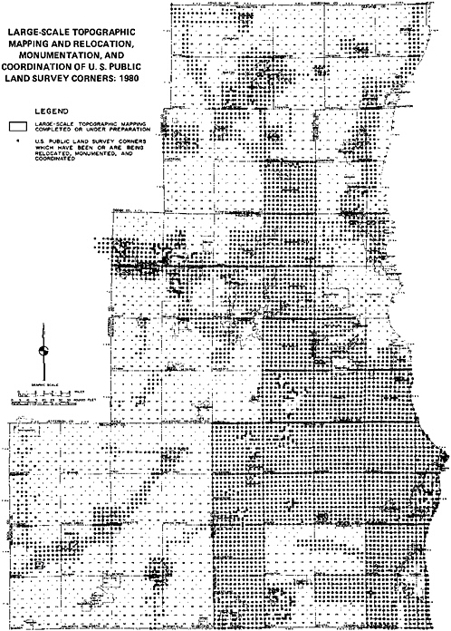
All the control survey work and attendant mapping have been carried out in accordance with a standard set of specifications provided by the Commission. These specifications call for the preparation of photogrammetrically compiled topographic maps that meet National Map Accuracy Standards at scales of 1:1200 or 1:2400, with a vertical contour interval of 2 ft, the maps being based on the herein described survey control system. Through the cooperative efforts of the Commission and certain county and local units of government, this survey control and mapping system to date has been extended into 1033 square miles, or over 38 percent of the total area of the region. A total of 5678 U.S. Public Land Survey corners have been relocated, monumented, and coordinated, representing over 48 percent of such corners in the region (see Figure A.1).
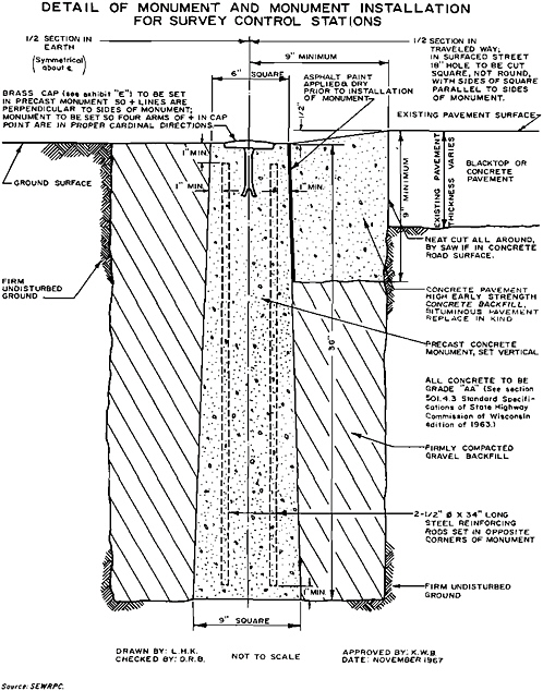
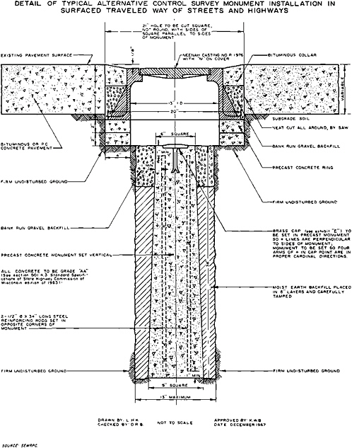
The specifications governing the work require that the relocated Public Land Survey corners be marked by reinforced concrete monuments, having engraved bronze caps imbedded in the tops (see Figures A.2 and A.3). The bronze caps are stamped with the corner notation—quarter-section, town, and range.
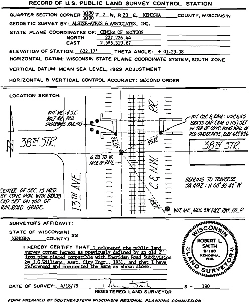
The monuments placed are referenced by ties to at least three witness marks. The specifications require that the survey engineer provide a dossier on each control station established in order to permit its ready recovery and use. The dossier sheets are prepared on 8 1/2-inch×11-inch base material and provide for each station a sketch showing the monument erected in relation to the salient features of the immediate vicinity, all witness monuments together with their ties, the state plane coordinates of the corner, its Public Land Survey description, the elevation of the monument, and of appurtenant reference benchmarks referred to National Geodetic Vertical Datum of 1929 (see Figure A.4). These dossier sheets are recorded with the County Surveyor as well as with the Commission and are thereby readily available to all land surveyors and engineers operating in the area mapped.
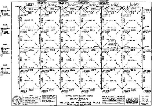
The specifications require the control survey data to be summarized by means of a control survey summary diagram showing the exact grid and ground lengths and grid bearings of the exterior boundaries of each quarter-section; the area of each quarter-section; all monuments erected; the number of degrees, minutes, and seconds in the interior angles of each quarter-section; the state plane coordinates of all quarter-section corners together with their Public Land Survey System identification; the benchmark elevations of all monuments set; and the basic National Geodetic Survey control stations utilized to tie the Public Land Survey corners to the horizontal geodetic control datum, together with the coordinates of these stations. The angle between geodetic and grid bearing is noted, as is the combination sea-level scale-reduction factor (see Figure A.5).
All the work necessary to execute the control surveys and provide the finished topographic maps described below has been done in southeastern Wisconsin on a negotiated contract basis with a photogrammetric and control survey engineer. In this regard it was considered essential to retain a photogrammetric and control survey engineer familiar with higher-order field methods and procedures and with the attendant geodetic survey computations and adjustments and whose crews were properly equipped with state-of-the-art survey instruments. Electronic distance-measuring equipment was employed in the work, as well as optically reading theodolites and appurtenant traverse equipment, automatic levels, and precision level rods. Indeed, the control survey system used is made economically feasible only through the application of these relatively recently developed instruments, particularly the electronic distance-measuring devices.
Although the specifications governing the work make the photogrammetric engineer responsible for overall supervision and control of the mapping work, as well as for the quality of the finished maps, they require that the actual relocation of the Public Land Survey corners be done by a local land surveyor employed as a sub-
contractor by the photogrammetric engineer. The specifications thereby recognize that this portion of the work requires expert knowledge of local survey custom and boundary and title law, as well as the assembly and careful analysis of all authoritative survey information—such as title documents, subdivision plats, survey records, and. of cardinal importance, existing monumentation and occupation—in order to arrive at the best possible determination of the location of the land-survey corners. In the areas mapped, the land-survey portion of the control survey work requires a very high degree of professional competence as almost all of the Public Land Survey corners fall under the federal definition of either obliterated or lost corners. The importance of this phase of the work and its impact on real property boundaries throughout the community can hardly be overemphasized.
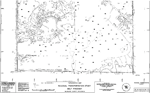
BASE MAPS—SUGGESTED USE OF LARGE-SCALE TOPOGRAPHIC MAPS
The specifications provide for the completion of finished topographic maps that can serve as the base maps for the preparation of a multipurpose cadastre by accurately recording the basic geography of the area mapped. In addition to showing the usual contour information, spot elevations, planimetric and hydrographic detail, and coordinate grid ticks, the maps show, in their correct position and orientation, all U.S. Public Land Survey quarter-section lines and corners established in the control surveys (see Figure A.6). The specifications require that the maps be prepared to National Map Accuracy Standards. Thus, all state plane coordinate grid lines and tick marks and all horizontal survey control stations must be plotted to within 1/100 inch of the true position as expressed by the adjusted coordinates for the control survey stations, and 90 percent of all well-defined planimetric features must be plotted to within 1/30 inch of their true positions, and no such features may be off by more than 1/20 inch. Ninety percent of the elevations indicated by the solid-line contours must be within one-half contour interval of the true elevation, and no such elevation may be off by more than one contour interval. A combination sea-level and scale-reduction factor, and the angle between geodetic and grid bearing, are noted on each map sheet, as is the equation between any local datum and mean sea level.
Importantly, all finished maps are field checked by the Commission. This check involves the field inspection of all control survey monumentation and the running of traverse and level lines to verify the accuracy of the basic control surveys, as well as of the map details.
CADASTRAL OVERLAY
Actual property boundary-line maps, complementing the topographic maps, are compiled by the respective local units of government, utilizing resident engineering and
planning staffs or consultants. Property boundary-line maps are compiled at a scale matching that of the topographic maps, each map sheet covering a U.S. Public Land Survey section or quarter-section.
As the topographic maps are being compiled, the specifications require that the photogrammetric engineer provide cadastral base sheets. These sheets consist of reproducible duplicates of the partially completed topographic maps showing, in addition to the state plane coordinate grid, the U.S. Public Land Survey section and quarter-section lines and corners in their correct position and orientation, together with their exact ground lengths and grid bearings, and such salient planimetric detail and hydrographic features as may be helpful in the subsequent plotting of real-property boundary lines, including roadway pavements, railway tracks, electric-power transmission lines, principal structures, fences, wetlands. lakes. streams, and drainage ditches.
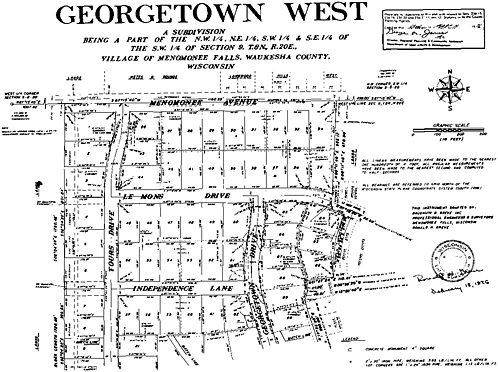
Utilizing recorded subdivision plats, certified survey maps, and legal descriptions, all real-property boundary lines, including street right-of-way lines and utility easement lines, are constructed on the base sheets working within the framework of control provided by the ground lengths and grid bearings of the U.S. Public Land Survey quarter-section lines. The property boundary lines are constructed in a manner that parallels the location of these lines on the surface of the Earth following land-surveying practice in the state of Wisconsin. The specifications require that all real-property boundary lines be plotted within 1/30 inch of their true position based on analysis of all authoritative information available. Dimensions are shown for all platted areas as shown on the recorded subdivision plats. Wisconsin statutes have long required that such plats be prepared to an accuracy of 1 part in 3000 as compared with the accuracy of 1 part in 10,000 required by the specifications for the basic survey control network. Any overlaps or gaps between adjoining property boundary lines, as indicated by the constructions and plotting of those lines, are noted on the cadastral maps. Finally, a cadastral parcel number is added, thus providing the basis for the development of the linkage mechanism necessary for the creation of a multipurpose cadastre.
The property boundary-line maps thus show the ground length and grid bearing of all quarter-section lines; the state plane coordinates of all quarter-section corners; the monuments marking these corners; the recorded dimensions of all street lines, alley lines, and boundaries of public property; recorded street widths; platted lot dimensions; and a parcel-identification number. In unplatted areas real-property boundaries are shown by scale alone. Roadway pavements, railway tracks, electric-power transmission lines, principal structures, fences. wetlands, lakes, streams, and drainage ditches are also shown (see Figure A.7). As previously noted, these boundary-line maps can be readily and accurately updated and extended as new land subdivision plats and certified survey maps, utilizing the survey control, are made and recorded (see Figure A.8).
The cadastral overlays can be readily converted to digital form using an interactive
graphic digitization and display system. This latter step toward the creation of an automated multipurpose cadastre has been accomplished only on a pilot basis within southeastern Wisconsin. A copy of a machine-produced cadastral map at a scale twice the base-map scale is shown in Figure A.9. The parcel-identification number serves as an index linking the parcel to title, tax, and public-land use regulatory information on file in various departments of county government.
Compilation of the property boundary maps in the manner described permits their reduction on a 10-to-1 ratio for the compilation of an accurate wall map at a final scale of 1:12,000 by mosaic process and at a 2-to-1 ratio for compilation of base maps for land subdivision planning and systems-engineering purposes. Contour information is, of course, readily and accurately transferable from the topographic maps by a simple overlay process.
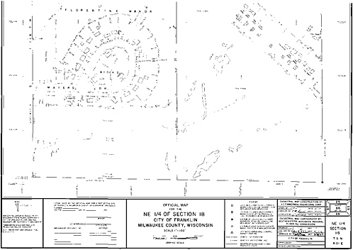
In Wisconsin the mapping procedure is carried one step further. Section 62.23(6) of the Wisconsin statutes provides that the Common Council of any city* may establish an official map for the precise designation of right-of-way lines and site boundaries of streets and public properties. Such a map has all the force of law and is deemed to be final and conclusive as to the location and width of both existing and proposed streets, highways, and parkways and as to the location and extent of existing and proposed parks and playgrounds.
The primary function of such an official map is to implement the community’s master plan of highways by, in essence, prohibiting the construction of new buildings in the mapped beds of future streets, as well as in the mapped beds of partially or wholly developed streets that are to be widened. A secondary function of the official map is to similarly implement the community’s master plan of parks and open spaces; and in this respect it can be used to protect scenic and historic sites, watercourses and drainageways, and floodplains and marshes. An incidental, but important, benefit accruing to the community through properly executed official mapping is, of course, the stabilization of the location of real-property boundary lines both private and public.
Insofar as the official map allows the municipality to reserve land for public purposes without commitment to actual purchase, it functions as a refinement of the community’s master plan, reflecting certain aspects thereof in a precise, accurate, and legally binding manner. On completion of the topographic and property boundary-line base maps described herein, specific projects—such as new major streets and highways, proposed street widenings, relocations, vacations, proposed parks, parkways, or drainageways—may be taken from the master plan, detailed as to specific location, placed on the base maps, and the base maps adopted as portions of the community’s official map. Thus, by exercise of the police power, property boundary lines can be stabilized and positive direction given to future community development.

FIGURE A.9 Conceptual design of DuPage Development Department data base.
COSTS
Costs of creating the described foundation for a multipurpose cadastre are recorded in four categories by the Commission: (1) land surveys, (2) control surveys, (3) topographic map compilation, and (4) cadastral map compilation. In any consideration of such costs, the complexity of the factors influencing the unit costs must be recognized, including particularly the size, configuration, and character of the area to be mapped. Based on the experience in southeastern Wisconsin, the costs of the land surveying entailed in relocating and monumenting the U.S. Public Land Survey corners, establishing the witness marks and related ties, and preparing the necessary dossier sheets and attendant certificates throughout the areas mapped has ranged from a low of about $60 per corner to a high of about $400 per corner, typically approximating $200 per corner in 1980 dollars. The control-survey costs, including estab-
lishment of state plane coordinates and elevations for the monumented U.S. Public Land Survey corners, has ranged from a low of about $70 per corner to a high of about $660 per corner, typically approximating $400 per corner in 1980 dollars. Topographic map-compilation costs have ranged from a low of about $580 to a high of about $8200 per square mile, typically approximating about $1700 per square mile for the 1:2400-scale mapping and $4200 per square mile for the 1:1200-scale mapping, including photography. Costs of preparing the cadastral maps have ranged from S10 to $40 per parcel. typically approximating $10 per parcel.
SUMMARY AND CONCLUSION
Properly designed and executed, a good local mapping program can provide the geographic reference framework, base maps, and cadastral overlay that constitute three of the fundamental technical requirements for the creation of a sound multipurpose cadastre and for its eventual expansion into a multipurpose land-data bank.
The geometric framework for the spatial reference of data is one of the most important factors on which the ultimate success or failure of any multipurpose cadastre and land data bank will depend. The necessary geometric framework must permit identification of land areas by coordinates down to the individual parcel level while permitting the precise mathematical correlation of real-property boundary and earth-science data. This requires the relocation and monumentation of all the U.S. Public Land Survey corners within the geographic area for which the land data system is to be created and the utilization of these corners in stations of high-order traverse and level nets tied to the National Geodetic Datum. The traverse nets establish the true geographic positions of the U.S. Public Land Survey corners in the form of state plane coordinates, thereby providing a common geometric framework for the collection and coordination of both cadastral and earth-science data, as described in Section 6.3 of this report. The monumented, coordinated corners in turn provide the basis for readily maintaining the data base in current conditions since all future surveys can be readily tied to these corners.
The specific geometric framework used in southeastern Wisconsin is, of course, applicable only to those parts of the United States that have been covered by the U.S. Public Land Survey System. The fundamental concept involved—the need to place both cadastral and earth-science data on a common geometric base—is, however, applicable to any area. In those portions of the United States that have not been covered by the U.S. Public Land Survey System, the application of this concept may well be more difficult and costly, requiring the incremental placement on the State Plane Coordinate System of some special network of survey control points adapted to each locality. Nevertheless, this work is just as essential if a comprehensive land-data system is to be created over time. Once the geometric framework is in place, the preparation of the base map necessary to record the basic geography of
the area and the preparation of the cadastral overlay to the base map become relatively simple operations. The preparation of such maps is, moreover, essential to sound community development and redevelopment, a fact that should dictate the preparation of such maps in any case.
The importance of the establishment of a sound geometric framework and related maps as a sound foundation for multipurpose cadastres and land-data banks is apt to be overlooked by decision makers as a technical detail in their deliberations over the other important issues involved in the creation of such systems. The establishment of a sound geometric framework, and the proper preparation of the related base maps and cadastral overlays is, however, a fundamental undertaking that clearly will require much understanding, foresight, and commitment on the part of the technicians and decision makers concerned. Failure to make the proper decisions concerning the basic technical foundation of any land-data system during its formative period will jeopardize the future utility of the system, for reform will become increasingly costly and difficult over time.
Appendix A.2
DuPage County, Illinois
INTRODUCTION
In late 1979 the County Board of DuPage County, Illinois, acted to create a county remonumentation and integrated computer-mapping program. In taking this action, the County Board recognized the high costs and inefficiencies attendant to inadequate survey control and mapping and the need to meet in a more consistent, coordinated, and cost-effective manner the control survey data and mapping requirements of the literally hundreds of government and private agencies operating within the county, utilizing the latest state-of-the-art technologies. The Board noted that cooperation on joint projects between county agencies had often been hindered by the inability of the departments to readily utilize each other’s data. In many instances, various levels and agencies of government, as well as private organizations, within the county were duplicating survey data or maps that already existed in some other department or agency files.
DuPage County is located in the Chicago metropolitan area. It has an area of about 340 square miles and a population of over 650,000 persons and is one of the fastest-growing counties in the United States. It is subdivided into over 250,000 parcels of land. All property descriptions in the county are based on the U.S. Public Land Survey System. As of 1979, however, only a very few of the approximately 1400 public-land survey corners in the county were permanently monumented. In many instances, conflicting locations for these corners resulted in gaps or overlaps in land-ownership descriptions and related uncertainties of title. Lack of geodetic survey control with respect to the section and quarter-section corners and attendant inability to relate real-property boundary-line data to a map projection made it next to impossible to compile an accurate cadastral map of the county.
DESIGN OF THE PROGRAM
The responsibility for implementing the program established by the County Board was assigned to the Supervisor of the Assessment. Maps, and Plats Division of the DuPage County Development Department. Recognizing the need for an overall plan to guide the execution of the County Board-mandated program, the Department retained a consultant with expertise in the field of cadastral and control surveys to help design and implement the control-survey and computer-mapping system. During the design phase of the program, three major goals were identified:
-
All public-land survey corners in the county are to be restored and monumented. The land survey work involved is to be done by local land surveyors retained for this purpose, working under the direction of the overall consultant. The corners are to be marked by cast iron monuments, and all the monumented corners are to be tied to the National Geodetic Survey Control Network and State Plane Coordinate values established for the corners.
-
The monumented survey control network is then to be used as a geometric framework for the development of a comprehensive mapping system that will meet the needs of all potential users. The maps are to be produced in digital form for computer manipulation so that map data could be readily produced at any scale or format desired. The major hardware components of the computer-mapping system will include a county-owned large mainframe computer and mass data storage units, input stations consisting of cathode-ray-tubc stations and digitizing tablets, and output stations consisting of plotters and line printers and attendant software programs.
-
The computer-mapping system is to be designed to interface with all county records also in the process of being converted to computer-rcadable form. Such interfaces will permit the linkage of zoning, building permit, and land-use information, as well as land-title record and tax-assessment information, to real-property parcels by machine.
INERTIAL SURVEY
To provide initial survey control both for the preparation of the orthophoto maps and for the subsequent coordination of the U.S. Public Land Survey corners, the National Geodetic Survey Control Network was densified utilizing inertial survey techniques. The inertial survey was designed to establish a horizontal control station every 2 miles throughout the county. Approximately 290 miles of inertial traverse were required to establish the horizontal and vertical positions of 53 control survey stations. The inertial traverse work was supplemented by an additional 21 miles of ground traverse to ensure that all the stations met second order, class II, standards. The total cost of this inertial control densification was approximately $40,000, or about $755 per station.
U.S. PUBLIC LAND SURVEY CORNER REMONUMENTATION
As of mid-1982, 185 public-land survey corners, including centers of sections, have been permanently monumented and tied into the State Plane Coordinate System. The remonumentation of the public-land survey corners is proceeding in parallel with the preparation of cadastral overlays for the previously prepared orthophotographs of each survey township in the county. The schedule calls for two survey townships to be completed each year, with the program being completed by the end of 1986.
The public-land survey corners are tied to the State Plane Coordinate System by conventional ground traverse. The cost of corner relocation and monumentation has approximated $825 per corner. The cost of establishing state plane coordinates and elevations related to the National Geodetic Datum has approximated $265 per corner.
ORTHOPHOTO BASE MAPS
Base maps are being prepared in a staged program in conjunction with the schedule of the remonumentation program; each map will cover one U.S. Public Land Survey section within the county. These base maps consist of 1:24,000-scale orthophotographs prepared by a photogrammetric engineer. The specifications governing the preparation of the orthophotographs required that the Illinois State Plane Coordinate System be marked on the photographs at 1000-foot intervals to National Map Accuracy Standards. To achieve the desired accuracy, control points were paneled prior to photography for later use in analytical aerotriangulation procedures. The preparation of orthophoto maps has cost $400 per square mile, while the cost of preparing the cadastral overlay to the orthophoto base maps has cost $2.00 per parcel, or approximately $1500 per square mile.
DIGITAL MAP SYSTEM
The computer-mapping system of DuPage County has been designed to meet the most demanding accuracy requirements, that is, for engineering plans. The remapping of each section will involve correlating all the survey data developed through the remonumentation program with existing plats of record.
In the spring of 1981 the county purchased the basic hardware for the system: a Tektronix 4054 graphics workstation (19-inch CRT, dual-disk drives, and 36-inch×48-inch tablet), and a Calcomp 970 plotter. The graphics workstation can operate either as a stand-alone computer, programmable in BASIC, or as a terminal of the county’s mainframe computer. The mapping data compiled through December 1982 will reside on the mainframe computer of the software consultant, to be installed on the county computer early in 1983.
DuPage County has completed about half of its plan to automate the land-data functions of the county government. Within a few years, daily operations such as building permits, land-use studies, and zoning enforcement all will be processed on the county’s computer.
TOTAL SYSTEM DESIGN
The DuPage County program is unusual, if not unique, within the United States in that it is proposing to create a multipurpose cadastre in a single operation spanning
TABLE A.1 Estimated Costs and Cost Savings of the DuPage County Computer-Mapping and Remonumentation Program (All Figures Computed as 1982 Dollars.)a
a period of about 7 years, including not only the provision of survey control, base maps, and cadastral overlays but also the digitization of the maps and the creation of a file permitting the correlation of all land-related county records by machine processing. The conceptual design of the system is indicated in Figure A.9. The project design consultant has provided estimates of annual cost savings in county and municipal mapping costs that amount to 58 percent of the expenditures required to complete the system, during the period 1980–1985, as listed in Table A.1. Overall, the DuPage County system is being implemented in substantial accord with the principles set forth in this report, with the promise of significant economies in the operation of key county departments over the years ahead.
Appendix A.3
Jefferson County, Colorado
INTRODUCTION
In 1977 the Commissioners of Jefferson County, Colorado, acted to create a Mapping Department and to charge that department with the responsibility of producing and maintaining accurate, up-to-date, large-scale maps of the county. In this action, the Commissioners recognized the importance of good maps to the planning for, and management of, a rapidly growing county that is an integral part of the five-county Denver metropolitan area. In the relatively short time since its creation, the Mapping Department has made significant progress toward meeting its charge of accurately mapping the county. The work of the department has consisted of a logical progression of steps leading in 1982 to the threshold of a computer-aided mapping capability and the creation of a digital geographic data base and has provided a foundation for the eventual creation of a multipurpose cadastre.
The major components of the geographic data base are an ongoing mapping program, a computer-aided geographic locator system, and a county data-processing system used by the County Assessor, the County Clerk and Recorder. and the County Planning and Engineering Departments. This case study focuses on the mapping program, which provides an important technical basis for the data base, describing the important components of that program.
SURVEY CONTROL
Even prior to the creation of the County Mapping Department, responsible county officials recognized the importance of good survey control to any mapping program.
Accordingly, the county and the National Geodetic Survey entered into an agreement to undertake a joint project to densify the basic first-order horizontal control network in the county. Prior to 1976 only three first-order horizontal control stations existed in the 780-square-mile county, all located on relatively inaccessible mountain peaks. Under the joint program, National Geodetic Survey crews established 51 first-order horizontal survey control stations within the county. The stations were marked by standard National Geodetic Survey concrete monuments with brass caps, and each monument was provided with reference and azimuth marks, as required by the National Geodetic Survey practice. The horizontal position of the stations, in terms of their latitude and longitude and corresponding state plane coordinates, were established by first-order triangulation surveys conducted to National Geodetic Survey Standards. The completed first-order triangulation network provides monumented stations at about a 5-mile spacing thoughout the county. The cost of the completed first-order triangulation network was $1350 per station.
County survey crews trained by the National Geodetic Survey then established an additional 100 secondary horizontal survey control stations within the county. These stations were marked by concrete monuments with brass caps; and the positions of these stations in terms of state plane coordinates were established by traverse surveys conducted to National Geodetic Survey Standards for second-order, class I, traverse surveys. The cost of this work was $500 per station. The second-order stations, together with the first-order stations, thus provided a control survey station spacing of about 2 miles throughout the county.
Subsequent to the establishment of these 151 first- and second-order horizontal control survey stations within the county, the county land development regulations were amended to require that all new land subdivisions be tied to the geodetic control survey network. The new regulations required that the ties be made by third-order, class II, traverse surveys. These regulations thus provide for the establishment of state plane coordinates on property boundary lines down to the parcel level. Since Colorado law requires that all subdivision plats also be tied to the U.S. Public Land Survey System, this provision in the county land development regulations also results in the establishment of state plane coordinates for section and quarter-section corners as a part of the land subdivision process. In the 3 1/2 years in which the survey tie requirement has been in effect, 295 U.S. Public Land Survey section and quarter-section corners have been recovered and placed on the State Plane Coordinate System. The cost of this work has been borne by the private developers involved in the land subdivision process.
Additional local cadastral survey control points are established on the boundaries of all subdivisions approved by the county, which are required to be monumented. The private surveyors who locate these monuments have been very supportive of the objectives of the county cadastral survey program, according to the staff of the Mapping Department, and have voluntarily submitted photocopies of their field notes. The modest additional costs of maintaining high standards of survey control, mon-
umentation, and documentation for the new subdivisions are passed on to the land developer and, eventually, to the buyers of the individual parcels.
ORTHOPHOTOGRAPHY
Following the completion of the first- and second-order survey control densification, a contract was let with a private photogrammetric engineering firm to produce orthophotography of the county. In the densification program, 110 of the first- and second-order horizontal control stations established were paneled; and in October 1976 aerial photography was obtained at a negative scale of 1 inch=1000 ft. This photography was then processed into orthophotography on dimensionally stable base material at a scale of 1:4800, the orthophotography being referenced to the Colorado State Plane Coordinate grid system. Each orthophotograph covers an 8000 ft× 11,000 ft area so that 271 orthophotographs would cover the entire county. The county maintains this 1:4800 base-map system for 214 of these -areas, excluding the southern one fifth of the county, which falls within the Pike National Forest.
The orthophotographs are updated using new aerial photography flown every 4 years. As section and quarter-section corners are recovered and tied into the State Plane Coordinate System, their locations are plotted on the orthophotographs. These orthophotographs form the basis for the preparation of all county maps. The preparation of initial orthophotographs cost $60 per square mile; subsequent updating of the orthophotographs cost $12 per square mile.
PLANIMETRIC MAP SERIES
Subsequent to the completion of the orthophotographs, the Mapping Department undertook the preparation of a planimetric base-map series for the county. The maps are produced by drafting in ink on pin-registered dimensionally stable base material overlays to the 1:4800-scale orthophotographs. Overlays to these planimetric maps show the locations of all the primary and secondary horizontal survey control stations, the locations of such section and quarter-section corners as have been recovered and placed on the State Plane Coordinate System; all platted subdivisions; all streets, highways, and railroads; and major topographic and hydrographic features. Certain source documents, including subdivision plats, street and highway right-of-way maps, and survey records are used in the compilation of the planimetric maps.
Each map sheet covers the same area as the corresponding orthophotography. The cost of the finished planimetric maps is $375 per square mile, exclusive of control and orthophoto costs.
However, the overlay of subdivisions is not yet a complete cadastral overlay because:
-
Standard parcel identifiers are not indicated on the subdivided parcels. Most county records are indexed according to the assessor’s block and lot numbers, but other maps must be consulted to determine the number of a given parcel.
-
The county has not had the resources to map property boundaries in the “aliquot lands” comprising most of the land area of the county, which to date have been subdivided with reference to the lines of Public Land Survey System (PLSS) sections and fractions of sections and not under subdivision plans approved by the county.
The latter situation underlines the need for locating all the corners and quarter-corners of the PLSS sections by state plane coordinates, so that this predominating system of rural property boundary markers may be spatially related to the county property map system.
CURRENTLY PLANNED SYSTEM EXTENSION
As of February 1982, Jefferson County has retained a licensed land surveyor to recover U.S. Public Land Survey section and quarter-section corners and to tie those corners to the geodetic control network in a systematic manner in order to provide a tertiary control network throughout the county. The Public Land Survey corners are to be tied to the National Geodetic Survey Network by traverse surveys conducted to third order, class I, standards. The resulting data are to be stored in the form of state plane grid coordinates in the county computer data bank and ultimately provide the framework for a digital mapping system.
A proposal has been submitted to the Jefferson County Commissioners for an entry-level computer-mapping system consisting of a desk-top graphics computer (with 64 kbyte of memory, expandable to 4 Mbyte), 20 Mbyte hard-disk systems, line printer, digitizer, and plotter. This system will expand the countywide Geographic-Information System, utilizing both digitized and engineering data, as an integral part of an overall Management-Information System.
Appendix A.4
The Philadelphia Area
INTRODUCTION
The Regional Mapping and Land Records (RMLR) program has been developing and testing a computerized system of large-scale digital mapping, joined to a parcel-based land-records data base, to serve the Delaware Valley region of Pennsylvania and New Jersey, which is centered in the city of Philadelphia. The program was organized in 1976 through the efforts of key individuals in local and regional government, utilities, and other private-sector interests, who had long worked from various perspectives with the inadequacies of existing land-records and mapping systems. In initiating the RMLR program the participating agencies recognized a number of common issues: the present mapping and data systems being separately maintained were obsolete and costly; there was significant duplication of effort in producing parallel sets of data and maps; new technology was available to produce more efficient systems; and the start-up cost of a new system made it prohibitively expensive if borne solely by a single user.
The principal elements of the RMLR system are (1) computerized digital maps produced at a variety of scales, jointly produced and maintained by a consortium of public and private agencies for the common use of all participants; (2) a federated data base consisting of a wide range of information files, produced and maintained individually by the participants and shared at the discretion of the owners; (3) coordination of the local map and data base with state and national programs to increase mutual support and eliminate duplication (Delaware Valley Regional Planning Commission, 1980).
With the present land-records and mapping system, each change in the Philadelphia street network must be updated 28 times in city agencies alone. A normal 50 changes each year results in 1400 changes in the street network maps. In addition, the data associated with these maps must also be updated. Similar redundancy has been experienced by each of the utilities in the region, as well as the title insurance industry.
There are over 650,000 properties in the city of Philadelphia. Another inefficiency occurs because of the lack of an uniform property identifier in the city and the physical separation of related land records. Sample information searches have revealed that it takes over 3 hours, excluding travel time, to find ownership, mortgage, lien, violation, zoning permit, land-use, assessment, and tax-revenue information on a specific property (Hadalski, 1982).
RMLR I PILOT PROJECT
In order to test the concepts of the proposed map system, RMLR conducted a pilot project within the Philadelphia metropolitan region. The specific objectives of the project were to test the technical methods and operating procedures proposed and to determine the costs and benefits of the proposed system. A 50-square-mile region in Montgomery County, in and around Norristown, Pennsylvania, was selected for the pilot project site. This area provided an excellent mixture of rural, suburban, and high-density urban land use, typical of most urbanized areas of the region. In addition, existing horizontal and vertical ground control was distributed in such a fashion as to be almost ideal for the project.
The pilot project design was completed in December 1976. A contract was negotiated in October 1977, and, after some last-minute fund raising, work began in February 1978. The direct RMLR budget was $100,000, with $75,000 being used for the pilot project contractor consultant, Vernon Graphics. The project steering committee was formed consisting of those utilities and governments making financial contributions. They included Philadelphia Electric Company; Bell of Pennsylvania; Philadelphia Gas Works; Pennsylvania Power and Light; Philadelphia Suburban Water Company; Montgomery County, Pennsylvania; City of Philadelphia; Bucks County, Pennsylvania; Chester County, Pennsylvania; Delaware County, Pennsylvania; the U.S. Army Corps of Engineers; and the Delaware Valley Regional Planning Commission. Advisory members to the steering committee included the Pennsylvania Land Title Association, the National Geodetic Survey, the U.S. Geological Survey, and other state and federal government agencies.
In planning for a regional mapping and data system, which would provide the base on which to build a comprehensive land-record system, the steering committee decided that the basic geography, which would include road cartways and center
lines, drainage, bridges, and railroads, should be of the highest degree of accuracy attainable under state-of-the-art technology. The system would be designed in such a fashion as to provide for all foreseeable future accuracy requirements. This resulted in the design of testing in the project to determine the scale of aerial photography needed to produce required degrees of accuracy, to evaluate the relative merits of various methods of photoanalytical aerotriangulation. and to determine the feasibility of direct stereo digitization (Delaware Valley Regional Planning Commission, 1980).
BASE MAPPING IN THE RMLR I PILOT PROJECT
Aerial photography was obtained at three different scales: 1:16,000, 1:8000, and 1:4000. The 1:16,000-scale photography was used for rural and suburban orthophotography and digital mapping at scales of 1:4000 and 1:2000. The 1:8000-scale photography was used for suburban and urban orthophotography, and digital mapping at a scale of 1:1000, and the largest-scale 1:4000 photography was used for urban digital mapping at a scale of 1:500.
All horizontal and vertical ground-control points were established and paneled prior to the taking of the aerial photography. In establishing supplemental control using analytical aerotriangulation for the purpose of leveling and scaling each photogrammetric stereomodel, two methods of adjustment were used: polynomial adjustment and bundle-block adjustment. Field surveys were conducted to check the results of each aerotriangulation adjustment method. Overall. the results of the bundle adjustment proved to be 20 percent more accurate than those developed by the polynomial method.
The orthophotographic negatives were compiled at four times the original photographic negative scale and, if required, subsequently enlarged to eight times the original scale with satisfactory quality. The digital-mapping data base was produced using direct stereo digitization, digitizing directly from the aerial photographic stereo model using stereo compilation equipment, with a direct link to the computer system. The project was designed to meet National Map Accuracy Standards. Digitized features included base-map features (roads. drainage, and railroads), contours. utility poles, utility transmission towers, manholes, fire hydrants, culverts, utility buildings. transformer pads, utility fences, gas-regulator boxes, generating-station facilities, pipeline traces, sewage disposal and waste-treatment plants, pumping stations, radio and microwave towers, and storage tanks. All digitized detail was reviewed on cathode-ray-tube screens as digitized and later at a second station for cleanup and enhancement of detail. Names, text, and proper identities were added during this phase for all features. Edit plotbacks of each map were made on a flatbed plotter in ballpoint on Mylar, with color separation to enhance readability. These plotbacks were reviewed for changes, additions, revisions. and corrections as required (Delaware Valley Regional Planning Commission, 1980.)
COSTS OF MAPPING IN RMLR I
The RMLR Steering Committee advises that any attempt to generalize from the costs experience described in this section should recognize the following: (1) the value of a multipurpose, multijurisdictional land-data system will be unique to the locality for which it was designed; (2) local administrative, managerial, and political conditions will present obstacles that are at least as difficult to overcome as the cost of the technology; (3) RMLR I was a demonstration of a variety of alternative procedures, not all of which will be implemented in subsequent operational phases of the project; and (4) the range of local conditions covered in RMLR I may have been too narrow a sample to be representative of the state of the art, especially since the “learning curves” affected the productivity of both the vendor and the users.
Table A.2 summarizes the costs of preparation of base maps in the RMLR I pilot project in 1978–1979 dollars, per square mile. The digital base maps include streets and alleys, drainage, railroads, buildings, and bridges (Hadalski, 1982).
Maps of cadastral parcels were digitized in the RMLRI Pilot Project in 1978 and 1979, testing two alternative procedures that varied in cost and capabilities of the digitizing systems and in the scope of the map files created. The more elegant procedure involved intelligent graphics terminals with software that computed selected dimensions of each parcel (such as frontage) and related them to the corresponding entries in the assessor’s file. The less-expensive procedure provided only limited interactivity, equivalent to automated drafting, but used the same data-base man-
TABLE A.2 Costs of Production of Base Maps in the RMLR I Pilot Project (1978–1979 Dollars per Square Mile)
|
Type of Area |
Rural |
Suburban |
|
Urban |
|
|
Map scale |
1:4,000 |
1:2,000 |
1:1.000 |
1:1,000 |
1:500 |
|
Aerial photography scale |
1:16,000 |
1:16,000 |
1:8,000 |
1:8,000 |
1:4,000 |
|
ORTHOPHOTO BASE-MAP COSTSa |
$255 |
$385 |
$1394 |
$1394 |
None at this rate |
|
Direct stereo digitization (excluding editing and audit corrections) |
$425 |
$575 |
$1144 |
$1950 |
$3015 |
|
TOTAL COSTS FOR DIGITIZED BASE MAPS AND ORTHOPHOTOS |
$680 |
$933 |
$2538 |
$3344 |
$4314 without orthophotos |
|
aIncludes aerial photography, photoanalytics, and aerotriangulation according to the fully calibrated bundle-adjustment method and orthophotography producing screened positives. |
|||||
TABLE A.3 Costs of Alternative Cadastral Mapping Procedures in the RMLR I Pilot Project (1978–1979 Dollars per Parcel)
|
Type of Area: |
Rural |
Suburban |
Urban |
|
Map Scale: |
1:4000 |
1:1000 |
1:500 |
|
A. With intelligent terminals |
$15.50 |
$6.00 |
$8.30 |
|
B. With entry of graphics only |
11.10 |
3.00 |
3.90 |
agement system. The costs of producing the digital cadastral overlays, per parcel, are summarized in Table A.3. These costs include parcel layout, parcel data entry, digitizing, ballpoint plotbacks, edit corrections, final ink plots, and supervision (Hadalski, 1982).
These cost figures clearly indicate that the highly automated RMLR system is cost-effective when compared with less-sophisticated conventional mapping. This will be increasingly so through the 1980’s as computer costs decline and the need for automation in data handling increases (Delaware Valley Regional Planning Commission, 1980).
PARCEL MAPPING IN RMLR I
To devise a Parcel-Information System that would better serve the needs of the assessor than existing property maps, digital property maps were prepared as a demonstration for 10 square miles of the RMLR I test area. Existing tax maps were used as much as possible as the source material for the digitization of parcels and their associated data. Digitized base-mapping elements were utilized in conjunction with orthophotography in the tax-parcel layout, ensuring complete compatibility of all features in the geographic and property map bases (Delaware Valley Regional Planning Commission, 1980).
The Recorder of Deeds and the Assessor of Montgomery County, Pennsylvania, who have been hosts to the RMLR I pilot project, have been stimulated by the RMLR program to organize an integrated land-parcel data base that now serves both offices and is being adopted by private title insurance companies as the definitive index of land parcels. The offices that maintain the cadastral parcel indexes and maps were brought together on the same floor with the deed recorder in the county building in Norristown, so that new parcel identifiers can be activated almost immediately when the documents creating the parcels are filed. The establishment of a parcel index for all land-title documents being filed at the Recorder’s Office was found to be within his existing statutory authority.
DATA PROCESSING IN RMLR I
The systems software and applications software developed in the RMLR I pilot project provide the control for the entry management, analysis, and output of both graphical and alphanumeric data. Multilayering of data types provides for access and retrieval of data by defined output map limits or name, categories of elements, x-y window limits, and coordinate search within a defined category. It is thus possible to choose an area of any size and shape and to request a variety of graphics and associated data. For example, one can request all the roads within a township in association with schools, firehouses, and police stations. Specific types of data, such as all parcels within a given area that fall within 100-year floodplains or that are assessed at between $25,000 and $50,000, or any types of data that can be oriented geographically, can be retrieved similarly (Delaware Valley Regional Planning Commission, 1980).
SUMMARY OF RMLR I OBJECTIVES AND RESULTS
-
Objective: Test the technology of large-scale digital mapping.
Results:
-
Large-scale direct stereo digitization does work well and can meet high accuracy standards.
-
The capacity of interactive graphics to manipulate and manage public files of geographic data is substantial.
-
At appropriate scales, a high rate of interpretability of features from aerial photography, including utilities, is very evident.
-
-
Objective: Develop detailed estimates of the costs of implementing a computer graphics system.
Results:
-
The RMLR I pilot project developed and analyzed costs for common elements and specific elements that provide a basis for planning a system.
-
-
Objective: Develop measures of the uses and benefits of a RMLR system.
Results:
-
RMLR I was able to identify many uses and applications of a more precise mapping system that covers the utilities, county and city functions, management, and graphics and data retrieval of a variety of information.
-
-
Objective: Develop a strategy for implementing a modern mapping system.
Results:
-
The RMLR I experience confirms that no major problems exist of a technical
-
-
-
nature. Rather, the problems may be institutional and therefore require involvement of technical, administrative, and financial management of a potential user organization or group (Delaware Valley Regional Planning Commission, 1980).
-
THE RMLR II PILOT PROJECT
To further demonstrate and test the technology developed for the RMLR I pilot project, especially its use in a dense central-city environment, a second pilot project has been initiated. RMLR II will cover an area 5 blocks square (0.27 square mile) within center-city Philadelphia that contains the tallest buildings in the region along with the most concentrated complexes of land use and subsurface infrastructure. It is part of the oldest survey district in the city, where property records are based on very old plans, some of which date from the late 1600’s. RMLR II is planned to develop updating and maintenance procedures, transmission procedures, and workstation support for further applications of the RMLR system. It will be handling special problems of ground control, paneling, aerial photo annotation, and stereo digitizing that were not encountered in the RMLR I project area. The project is being augmented by special contracts for individual agencies within RMLR to develop (1) special software routines, including a DIME to RMLR interface; (2) specialized workstation training; and (3) “scanning” as a separate procedure to enter property boundary data into the digital data base.
Aerial photographic coverage of a larger area of 1.72 square miles, including center-city Philadelphia, was flown in mid-July 1982 at scales of 1:8000 and 1:4000. Fifteen existing ground-control points were available to control analytical aerotriangulation using the photographic coverage. The planimetric base maps are to be stereo digitized at a scale of 1:500 according to National Map Accuracy Standards. The planimetric features are being digitized in separate data layers to permit computer plotting of any individual data layer or any combination of data layers. The following data categories are being used:
|
Basic Map Features (cartways, traffic islands) Street Light Poles Utility Poles Traffic Light Standards Manholes Fire Hydrants Culverts Catch Basins Steam and Gas Vents |
Telephone Booths Radio, TV, Microwave Towers Bus Shelters Trees Subway Entrances Subway Vents Subway Lights Bollards Serving Area Connectors (Telephones) |
|
Buildings Fire Stations Police Stations Hospitals and Health Centers Educational Centers Historical Buildings Municipal Buildings Utility Buildings |
Transportation Facilities Other Parks Signposts Street Centerlines and Intersections Service Vents |
For each data category in which names are associated with a data item, such as streets or buildings, a data base of names will be kept for retrieval and plotting. The planimetric digital data base will allow the flexibility of plotting with reference to any of the following three horizontal reference datums: South Zone of the Pennsylvania State Plane Coordinate System, latitude and longitude, or Zone 18 of the Universal Transverse Mercator (UTM) 6° Grid. The system will provide for computer plotting of any specific portion of the data base at any specified scale in any combination of data layers (Smith, 1982).
Within the digital planimetric base map area of the RMLR II pilot project there exist approximately 4300 deeded properties, including over 2000 parcels, 2000 condominium units, and 13 airspace rights. Twenty-two tax plats are associated with the area. Using the computer-plotted basic map features and buildings as a base map for new tax plats, the city of Philadelphia Records Department will be adding parcel boundary lines, street right-of-way lines, and associated text. The parcel boundary lines will then be digitized into a digital data layer, parcel centroids determined, and parcel-specific information added to the data base from the files of the city of Philadelphia Board of Revision of Taxes, to be merged with the information from the Records Department.
In order to ensure that the digital data tapes will be compatible with the operating systems of the major participants in the project, IBM IGGS Interface Format has been specified. This will permit greater in-house use of the generated digital data in an operational environment, for additional testing and procedure validation.
By maintaining detailed cost records of each phase of the RMLR II pilot project, the RMLR steering committee will have a firm base for the formulating of future project decisions.
With the awarding of the RMLR II contract, the city of Philadelphia, Philadelphia Electric Company, Philadelphia Gas Works, and Southeastern Pennsylvania Transportation Authority (SEPTA), along with the Delaware Valley Regional Planning Commission are continuing their commitment to go forward together, at a cautious pace, in building a modern, large-scale digital-mapping system. These leaders of the RMLR program appear to have developed a successful formula for joint sponsorship and use of the mapping system by the local government and the major utilities, which has eluded so many others.


