
2
The Geodetic Reference Framework
2.1
BACKGROUND
A geodetic reference framework forms the spatial foundation for the creation of any Land-Information System (LIS). Consisting of monumented points whose locations have been accurately determined with respect to a mathematical framework, this system permits the spatial referencing of all land data to identifiable positions on the Earth’s surface. A geodetic reference framework provides not only an accurate and efficient means for positioning data, but it also provides a uniform, effective language for interpreting and disseminating land information.
2.1.1
The National Geodetic Survey
The National Geodetic Survey (NGS) is mandated by law to establish and maintain a National Geodetic Reference System (NGRS) adequate for present and future public needs. The present NGRS is a network of close to 750,000 monumented control points whose precise geographic positions or elevations. or both, have been determined by geodetic surveys. This network is the basic positioning reference for all U.S. mapping and charting, large-scale engineering works, national defense operations, Earth satellite tracking, and a wide variety of other national and local endeavors. It provides the only practical means for determining the relative positions of widely separated points in a common, unified coordinate system. Government and private survey organizations use NGRS stations as absolute reference points for local surveys to minimize the propagation of errors that would otherwise result in the mispositioning of property boundaries, engineering works, and other features.
To eliminate discrepancies between adjacent surveys and to ensure that each land parcel is uniquely positioned and identified. communities have had to abandon local datums and isolated coordinate systems and integrate area systems with the NGRS. This has become especially critical for communities that maintain computerized data bases that cannot tolerate ambiguities.
The NGRS consists of surveys from sources other than the NGS, including other federal agencies, state agencies, and private surveying/engineering firms. Coordination is accomplished by adoption of procedures established by the interagency Federal Geodetic Control Committee (FGCC). By Office of Management and Budget directive and interdepartmental agreement the FGCC reviews governmentwide requirements and programs for geodetic activities and makes determinations if surveys can be practicably and economically improved and permanently monumented to form a part of the national networks. The integrity of the NGRS is maintained by adoption of the FGCC standard “Classification, Standards of Accuracy, and General Specifications of Geodetic Control Surveys.” Surveys are forwarded to NGS for adjustment and inclusion in the NGRS by adopting the FGCC standard “Input Formats and Specifications for the NGS Data Base” (Federal Geodetic Control Committee, 1980).
Available from the National Geodetic Information Center (NOAA, NGS, Rockville, Maryland 20852) are maps depicting the available points in the NGRS. Available are horizontal coordinates and descriptions for 250,000 points and elevations and descriptions for another 500,000 points. Availability is in hard copy and digital form (magnetic tape or microform). Recently, the horizontal data base has become available by a direct telecommunications link.
2.1.2
State and Local Geodetic Networks
Responsibility for the coordination of geodetic control activity at the state level varies from essentially no organization or coordination in some states to the existence in other states of strong state geodetic survey agencies. In many states, leadership resides within a state department of transportation, division of surveying and mapping (or equivalent). In 17 states, there is an office of state surveyor (or equivalent), which has been established by state statute to coordinate surveying activity.
The federal government has provided each state in the United States with a plane coordinate system based on the NGRS and one or more zones of either the Transverse Mercator projection or the Lambert Conformal Conic projection. The present State Plane Coordinate Systems were first introduced in the 1930’s and are based on the 1927 North American Datum. They have been ratified by legislation in 38 states.
At the regional, county, and local levels, geodetic control activity is carried out both by private surveyors and engineers, in response to the needs of specific projects. and by state and local governments, usually the survey crews of the public works departments.
2.2
GEOMETRIC FRAMEWORK REQUIREMENTS FOR THE CADASTRE
Any Land-Information System requires some method of spatial reference for the data. An adequate geometric framework for such reference must, if it is to serve even the narrowest of purposes of a cadastre, permit identification of land areas by coordinates down to the individual parcel level. The provision of a geometric framework of adequate accuracy and precision to permit system operation at the highly disaggregate parcel level is the most demanding specification possible. It permits ready aggregation of information from the more intensive and detailed level to the more extensive and general level as may be necessary.
The type of geometric framework to be provided for any new land-data system is one of the key determinations affecting the long-term, as well as the initial, utility and efficiency of the system. Any error in this determination should be made on the side of potential long-term utility. A determination to provide a geometric framework more precise and accurate than may be required ultimately will mean that a portion of the capital required to implement the system may be wasted. A determination, however, to provide a geometric framework less precise and accurate than may be required ultimately will mean that most or all of the capital investment required to implement the system will have been wasted. Further, such a misapplied capital investment itself may form an insurmountable impediment to later evolutionary development of the system, since the committed decision will with time make it increasingly difficult and costly to effect any required reforms. In this respect, it is particularly important to resist the temptation to use only paper records of mapped locations as a basis for the development of the land-data system in order to save initial costs.
Because of the importance of the geometric framework for the spatial reference of data to the long-term success of any multipurpose land-data bank, and because that importance is apt to be overlooked by planners and decision makers in their deliberations of other important issues involved in the creation of land-data systems, a brief discussion of certain fundamental concepts that should be applied in the design of the geometric framework for any land-data bank system is in order.
2.2.1
Fundamental Concepts
An effective multipurpose land-record system must be able to store in machinereadable form a wealth of data essential to sound land-use planning and management. Historically, such data have been typically stored on maps. Consequently, certain concepts that apply to the design and preparation of good maps also apply to the design and implementation of the geometric framework for a land-data system.
Any accurate mapping project requires the establishment of a system of survey control. This survey control consists of a framework of points whose horizontal and vertical positions and interrelationships have been accurately established by field surveys and to which the map details are adjusted and against which such details can be checked. The survey control system should be carefully designed to fit the specific needs of the particular map being created. For multipurpose application, it is essential that this survey control system meet two basic criteria if the maps are to be effective planning and management tools. First, it must permit correlation of realproperty boundary-line data with topographic, earth-science, and other land and landrelated data. Second, it must be permanently monumented on the ground so that lines on the maps may be reproduced in the field when land-use development and management projects reach the regulatory or construction stage. That is, the survey control system must support the production of finished maps, the points and lines of which not only accurately reflect both cadastral and earth-science field conditions but also can be readily and accurately reproduced on the ground. This capability is important not only to the use of the maps but also to their maintenance in a current condition.
Conceptually, the geometric framework for a Land-Information System is the equivalent of the survey control system for a map; and the same principles apply to its design and implementation.
2.2.2
Design Issues
In the design and development of a geometric framework for a land-data system, three important issues require resolution. One issue relates to the type of mathematical map projection to be used as a basis for the geometric framework. The second relates to the density—or control-station spacing—requirements for the framework. The third relates to the accuracy requirements for the framework. The determinations concerning these three issues should be made in light of the basic concepts set forth above.
The curved surface of the Earth cannot be represented on a plane surface such as a map without distortion that increases with the size of the area involved. Accordingly, a projection that can be used to transform geodetic positions on the surface of the Earth to corresponding plane coordinate positions on the map is required. Properly selected, the map projection becomes a powerful mathematical tool for performing rigorous survey computations as well as providing a basis for the accurate graphical representation of the mapped data.
A number of projections have been used as a basis for the preparation of largescale maps. The federal government through the NGS has provided practical projections for use in local surveying and large-scale mapping operations through the State Plane Coordinate Systems. The principles underlying the State Plane Coordinate
Systems and the data necessary for their application in the development of a geometric framework for a land-data system are set forth in publications of the NGS (Special Publication Numbers 235 and 62–4).
The universality of coordinate values expressed in terms of the State Plane Coordinate Systems provides a compelling argument for the use of these systems in the development of a geometric framework for land-data systems. The state plane coordinates can be transformed readily, precisely, and within known accuracy limitations into other coordinate systems, thereby permitting the correlation and use of the data in regional, state, and national as well as in the local systems.
We recommend the use of the State Plane Coordinate Systems as the basis for the recording of positions in local land-data systems in the United States. Selection of any other projection should be done reluctantly and only after most careful consideration.
The second major issue to be addressed in the design of a geometric framework for a land-data system is the necessary density of the horizontal control network. If the positional integration of the land data is to be accomplished solely by graphic means—the necessary correlations being provided solely by reference to the coordinate grid shown on the maps—only the density of control needed for the maps is required. If, however, the integration of the positional information is to be accomplished numerically, relatively high-density standards are required. Numeric integration of the data should be an essential feature of any modern land-data system, and the density and accuracy requirements of the horizontal survey control should be determined accordingly.
Monumented points of known position on the State Plane Coordinate System should be so distributed throughout the area concerned as to permit their ready use in the collection of both cadastral and earth-science data. Typical recommendations range from 0.2 to 0.5 mile (0.3 to 0.8 km) between monuments in urban areas to I to 2 miles (1.6 to 3.2 km) in rural areas (Ziemann, 1976; McLaughlin, 1977). We concur with these recommended densities of monumented points. In those areas of the United States covered by the PLSS. monuments established at approximately one-half-mile intervals at section and quarter-section corners and at the centers of sections would meet the system design for control stations. An accurate position of the center point of a section is required in order to provide a proper basis for the compilation of cadastral maps and data.
Ideally, the entire area concerned should be covered at a uniform density with a simultaneously adjusted network of control survey stations. As a practical matter, however, the necessary survey work will have to be carried out over an extended period of time. To provide the required uniformity in such successive surveys, a higher-order control net may have to be established. The spacing of the higher-order stations can be up to 10 miles (16 km) but is usually 3 to 5 miles (5 to 8 km). In any case, the local survey network should be an integral part of regional, state, and national control nets.
With respect to accuracy, the determining factor will be the extent to which the control survey stations are to serve multiple purposes. Similar to the above, if the integration of the positional data is to be done graphically, a relatively low order of accuracy will be required for the horizontal control network. such as that attendant to the federal classification of third-order, class II (Federal Geodetic Control Committee, 1978). If, however, the data are to be integrated numerically and if the control surveys are to have multiple applications, minimum accuracies at least attendant to the federal classification of third-order, class I, or second-order, class II, should be met.
As a final consideration. all the control stations should be monumented with substantial, stable, readily recognizable survey monuments. The monuments should be accurately tied to at least three reference marks. and documentation should permit their ready recovery and use both for the maintenance and extension of the basic control net and, importantly. in the collection and use of the land data themselves.
2.2.3
The Public Land Survey System
The Public Land Survey System (PLSS) was organized starting in 1785 as the geometric framework for all lands that at that time were the responsibility of the federal government and part of the public domain. Those lands, and the vast areas that subsequently were acquired by the U.S. Government. today exist within 30 states that contain 80 percent of the land of the nation and are home to 56 percent of its population.
The PLSS provides a unique identifier for each mile-square section in these lands and may be used to identify fractions of sections as small as 2 1/2 acres. The boundary lines are defined by monuments placed at intervals of 1/2 mile in the original survey of each section commissioned by the federal government. If these monuments are lost, then replacements are valid only if placed in a survey that “follows in the footsteps of the original surveyor.” A summary of the history and structure of the PLSS is presentcd in Chapter 2 of the report of the Committee on Integrated Land Data Mapping (1982).
The property boundaries defined by the original PLSS monuments have the attributes of registered property boundaries in that they are immune to relocation by “adverse possession,” even by fence lines that are long established. The correct, legal locations (or relocations) of the monuments are the very foundation that holds the PLSS together and without which the definitions of property boundaries in vast areas of the United States would come unraveled.
For all the nonfederal lands in the United States that are subdivided according to the Public Land Survey System (PLSS), we recommend that the geodetic reference framework for the cadastre be the section corners and quarter-section corners of the PLSS, including the center point of each section. In the non-PLSS states, an even distribution of selected property corners or eccentric corners and righl-of-way
monuments should form an equivalent framework. Each county (or municipal) cadastre program should be made responsible for assuring that these points have been relocated and monumented according to the legally established procedures prevailing in each state and property connected to the National Geodetic Reference Framework to obtain geodetic coordinates.
The spacing of survey control points at intervals of 1/2 mile that is recommended here is consistent with the standard for urban areas recommended in the preceding section. For rural areas in the PLSS states, this relatively close spacing is justified as a completion of the monumenlation of the basic framework of rural property lines, none of which would be delineated if only the section corners at 1-mile intervals were accurately located. At least one end of every PLSS property line depends on reference to a quarter-section corner to establish its position, and every PLSS property line would be left floating if only the section corners at 1-mile intervals were located, except in the relatively few areas of the PLSS where no quarter-section corner monuments ever were put in place. Figure A.5 of Appendix A.1 shows how the basic framework of property lines is completely defined by the survey control points at half-mile intervals.
This recommended density of survey control in the 30 PLSS states and the 20 “metes and bounds” states has the following important advantages:
1. It provides a common, consistent, and accurate system of control for both real-property boundary lines and topographic mapping. In the 30 PLSS states the boundaries of the original government land subdivision form the basis for all subsequent property divisions and boundaries; thus the accurate re-establishment of the U.S. Public Land Survey quarter-section lines and corners permits the compilation of real-property boundary-line maps and supports the compilation by usual photogrammetric methods of topographic maps. Moreover, in any state that requires all new land subdivision plats to be tied by surveys of a specified accuracy to the available geodetic control points, these boundary-line maps can be readily and accurately updated and extended into newly developing areas. The inclusion of State Plane Coordinates on these plats can be readily required by local subdivision regulations.
The system permits the accurate correlation of property boundary-line information with topographic details supplied by aerial mapping. This placing of property-boundary and topographic data on a common datum is essential to sound mapping for the ultimate development of a multipurpose cadastre, as well as for planning and engineering purposes, yet such a common control datum is rarely used. The eslablishment of State Plane Coordinates for a dense network of survey control points permits the transfer of details supplied by aerial mapping, including hypsography, to property boundary-line maps by simple overlay methods. Savings in office research time made possible during the planning and design phases of municipal public works projects by having all available information—topography, property boundaries, and control—
accurately correlated on one map are great. Moreover, such complete and correlated information and control makes possible the consideration and analysis of many alternate routes for such public works facilities as trunk sewers, water transmission lines, and major trafficways and of many alternative solutions to sewerage, drainage, water supply, and transportation problems.
2. It provides a practical horizontal control network readily usable by both private and public surveyors and engineers for all subsequent survey work within the urban area. The control system outlined places a monumented, recoverable. control station of known position and known elevation at half-mile intervals throughout the area mapped. This monumented control net not only expedites such engineering surveys as are made almost daily, year in and year out, by such public works agencies as city engineering and water departments; county and state highway departments; and sewerage, transportation, airport. and harbor commissions for planning, design, and construction layout purposes, but also correlates and coordinates all their survey work throughout the entire area mapped. In this regard the control system outlined is particularly valuable in providing a common system of control for the precise location and mapping of underground utilities, both public and private.
3. It makes the State Plane Coordinate System available as a practical matter for property boundary-survey control, thus providing the means for using State Plane Coordinates in boundary descriptions supplcmented in 30 states by the PLSS. In most of the United States it would be the first meaningful control net available to the land surveyor. Property corners, in many urban areas, have long been inadequately monumented and, therefore, readily susceptible to loss. Points of beginning in a metes and bounds legal description have often depended .on unmonumented corners or on street and highway intersections that cannot be relocated precisely. The accurate retracement of property boundaries under such conditions is extremely difficult and costly, and the accurate mapping of such boundaries by public agencies is well nigh impossible. Moreover, the uncertainties of title and accompanying litigation resulting from such conditions become more and more unsatisfactory as urbanization intensifies and land values increase. By requiring the relocation and permanent monumentation of the Public Land Survey corners, which cover 80 percent of the United States, the recommended system will do much in itself to stabilize real-property boundaries and make the control net of great value to private land surveyors. By utilizing this control, local land surveyors can, without changing their methods of operation or incurring any additional expense, “automatically” tie all their surveys to the State Plane Coordinate System, and all bearings used in land surveys, plats, and legal descriptions will be directly referenced to grid north and thereby to geodetic north. If the use of the State Plane Coordinate System is to be encouraged, it is essential that it be made available in this manner to the local land surveyors. While the State Plane Coordinate System was devised by the U.S. Coast and Geodetic Survey (now the National Geodetic Survey) in the early 1930’s, it has seen only limited use in many areas by land surveyors and local engineers, who have generally been unfamiliar with both
the system and the methods necessary to carry geodetic control down to the property being surveyed. Only by making state plane coordinates available to the surveyor through the PLSS, which he understands and employs constantly, can their use in land and local public works engineering surveys be achieved practically.
4. It would reinforce the many other values of the PLSS in the 30 states now using that system. Lines of the PLSS drawn on the cadastral maps are guides for reserving land for future public use. taking land for public use, describing districts within which public regulations are to be applied, or locating and aligning proposed public works projects. The PLSS is economically adaptable to the latest survey techniques. The PLSS supports the eventual creation and maintenance of a multipurpose cadastre and a multipurpose land-data bank.
The cost of control surveys for aerial mapping projects typically accounts for one quarter to one third of the total cost of the finished maps. Such control surveys are unusable by local engineers and surveyors, and their costs are largely unrecoverable. By allocating to the control survey work a relatively small additional amount of the total resources that might be available for mapping, far more effective and useful finished maps can be obtained. and a valuable and permanently useful system of survey control can be provided concurrently. The only significant increases in cost actually assignable to the control system proposed are relatively small and are solely those incurred for the relocation and monumentation of the land-survey corners and the small amount of additional traversing required to coordinate these corners. These additions to cost amount to approximately 20 percent of the total cost of an urban mapping project—small in relation to the benefits.
2.3
OUTLOOK FOR NEW TECHNOLOGY
To date, a geometric framework that would support a multipurpose cadastre exists in a small fraction of the counties in the United States. Indeed, in only about 10 percent of the 500 counties designated by the U.S. Department of Commerce as “leading” counties in terms of economic activity is therein place an existing primary geodetic framework of sufficient density (spacing of 3 to 5 miles or less) (or 5 to 8 km or less) to serve as a logical starting point for densification to a level that would support the cadastre. Although there are multitudes of PLSS section-comer monuments in 30 states, relatively few of them have been located with reference to a coordinate system in a manner that will support planning and engineering. Because of limitations of staffing, the National Geodetic Survey has had to turn down or table requests from scores of counties for establishment of primary nets. Thus, most counties are not even in a position to begin the establishment of the local geometric framework required to support a cadastre.
Even where the primary geodetic net is already in place, it could well take a decade for a single surveying party to complete a project of densification sufficient to support a multipurpose cadastre for a typical county (Brown, 1977). Moreover,
total costs for a county of average size could easily entail several million dollars, as described in Section 7.3.2. Examples of such long-term county programs are described in Appendix A.
Fortunately. much progress has been made toward the introduction of more effective and efficient positioning technologies that permit substantially lower perunit costs for large-scale densification of survey control. Some of these, such as photogrammetric triangulation, are well-established technologies. Others, such as the Global Positioning System (GPS), are just becoming available.
2.3.1
Photogrammetric Triangulation
The most mature and well-documented alternative to field surveying is photogrammetric triangulation. With this technology an area is covered by a block of photographs having a high degree of overlap (at least 60 percent in both directions) so that each point of interest is imaged in nine or more photographs. A small number of previously surveyed points serve as a framework of control within which all other points are established by an interpolative process based on measurements of the coordinates of images on film. The most rigorous and accurate approach to photogrammetric triangulation is by the “bundle-adjustment method” (Brown, 1973). This involves the simultaneous least-squares adjustment of the sets (or bundles) of rays from all photographs to all measured ground points in a process that also simultaneously recovers the projective parameters (position and attitude) of all photos. In a more advanced version referred to as the “bundle adjustment with self-calibration” the process is expanded to include the estimation of additional unknown parameters (or error coefficients) that describe residual systematic errors in the observations. In blocks with relatively sparse control, the bundle adjustment method with self-calibration can provide a significant improvement in accuracy.
One especially important feature of the bundle-adjustment method is that it does not require that horizontal control be distributed fairly uniformly throughout the area in the manner considered desirable for densification by conventional ground methods. Rather, it suffices if such control is distributed about the periphery of the block with a spacing corresponding to that of about every fifth photograph. With such control. accuracies in planimetry turn out to be nearly uniform throughout the photogrammetric block, no matter how many photographs are contained in the block. This means that densification by the bundle method requires far less primary control than is needed for densification by ground methods. As is pointed out in Brown (1971), savings resulting from sharply reduced requirements for primary control may often be sufficient to pay for all costs of photogrammetric densification except those associated with monumentation. In a subsequent study, Brown (1977) found that photogrammetric triangulation could provide as much as a 3-to-1 cost advantage over firstorder ground traversing. Furthermore, at least in principle. almost any desired accuracy can be produced by photogrammetric triangulation (it being primarily a function of the scale of the photography). According to recent tests conducted by NGS
(Lucas, 1978) accuracies approaching 1/100,000 of the flying height can be approached when highly exacting procedures are employed (including adjustment by the bundle method) and when a modern aerial mapping camera of 6-inch (150-mm) focal length is used in conjunction with a focal-plane reseau (a device that projects at uniform intervals throughout the format sharply defined points of reference that serve to account for effects of film deformation). Accuracies of bettcr than 1/50,000 of the flying height have been reported by Europeans employing cameras without focal-plane reseaus. In other words, accuracies of 0.1 ft (3 cm) are being realized when the flying height is 5000 ft (1500 m) or less.
However, aside from a few pilot tests of relatively limited scope, no significant application of photogrammetry to the establishment of a geographic data base has been reported to date. The technology reached maturity over 5 years ago, and its capabilities and advantages have been widely disseminated throughout the technical community. It appears that a major impediment to its practical utilization stems from a lack of recognized standards for photogrammetric triangulation. Many methods exist, and their accuracies may vary by a factor of 10 (Brown, 1973). This proliferation of methodology is confusing to the uninitiated and will be a continuing obstacle until suitable photogrammetric standards are adopted.
2.3.2
Inertial Surveying
Another important emerging technology is inertial surveying. This technology had its beginnings at the outset of the 1970’s in a military system designed originally for artillery surveying to accuracies of ± 30 ft (±9 m) over open traverses of about 120 miles (193 km). However, the original Position and Azimuth Determining System (PADS) displayed a potential for considerably greater accuracies, and subsequent improvements in hardware, software, and operating procedures have rapidly elevated the system to a level of accuracy competitive with conventional second-order traversing.
The heart of an inertial surveying system is an inertial navigational unit designed for use in aircraft. The Litton LN-15 inertial navigator, employed in the first of the inertial surveying systems to be developed, has a basic drift rate in application to aircraft navigation of about 1 km (3300 ft) per hour of flight. On the other hand, in applications to ground surveying this performance is effectively improved by a factor of several thousand. Such drastic improvement has come about largely through exploitation of the fact that in ground surveying the vehicle bearing the inertial unit can be brought to a dead stop at frequent intervals. During such stops, which are called zero-velocity updates, residual components of velocity attributable to drifts in the system will be sensed (these would be zero in a flawless system). Such discrepancies generate observational equations that are processed in real time by an onboard computer. This leads to estimation and partial compensation for drifts in the inertial unit. Further compensation can be made through apportionment of errors of closure on points whose coordinates are known (control points). An analysis of results from
a large number of field tests provides the following estimates of the accuracies of an inertial surveying system (Mancini, 1977):
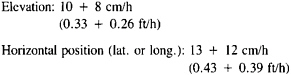
These estimates are based on operations involving zero-velocity updates (stops of about 30-sec duration) at intervals of 3 to 5 min and an apportionment of errors of closure on control points. An interesting facet of an inertial survey is that, up to a point, the faster it can be performed the more accurate it is, for the buildup of error is predominantly a function of time rather than distance. For this reason a helicopter is generally the preferred vehicle whenever feasible.
Accuracies of inertial surveying for relative positioning for successive points that are relatively close together (as in urban densification) are dependent mainly on the constant term (or “threshold”) in the expressions given by Mancini (1977), because the time required to travel from one point to another is only a matter of a few minutes. Thus, accuracies in relative horizontal positioning of such points can be expected to be roughly on the order of 13 to 18 cm (0.4 to 0.6 ft). For points separated by 800 m (about 0.5 mile) this corresponds to a proportional accuracy of about I part in 4400. On the other hand, relative horizontal positions for a pair of points, say 10 min and 10 km (6 miles) apart, could be established to a proportional accuracy of almost 1 part in 50,000. This indicates that under certain circumstances inertial surveying can produce accuracies equivalent to those of conventional second-order traversing. Howwver, it appears that an improvement by about a factor of 2 to 3 is needed if positions of closely spaced urban monuments are to be established to the desirable level of accuracy of about 5 cm (0.2 ft). With the rapid developments in this field, it is probable that this accuracy will be achieved in the near future.
The Bureau of Land Management, U.S. Department of the Interior, has had extensive experience with inertial surveying technology for cadastral purposes. They have employed a system consisting of six components, all interconnected by a system of electrical cables and installed in a helicopter. These components are the inertialmeasurement unit, data-recording unit, power-supply unit, data-processing unit, control and display unit, and auxiliary battery. Total weight mounted in a helicopter without battery is about 125 kg (275 lb). The control and display unit is mounted on the helicopter instrument panel. The remaining components are secured to a plywood pallet mounted in the rear seat area. An optical hoversight device is mounted in front of the pilot, which enables him to hover directly above any point on the ground.
The system has been used to determine geographic coordinates and elevation of PLSS section corners in relation to other points having known coordinates and elevation. As the system is transported by helicopter, incremental velocity changes
are automatically recorded in three directions at short intervals of time. These velocities are integrated to obtain a continuously updated set of coordinates and elevation of the instantaneous location of the system. The coordinates and elevation of all other section corners in the township are determined by hovering over each point and reading the system display directly. In actual field use, the point coordinates are stored in the computer memory for later computer processing.
The cost of currently available inertial surveying units is quite high—on the order of several hundred thousand dollars. Should more compact and cheaper inertial surveying units eventually become almost as widely used as first-order theodolites are today, their use could extend to routine property surveying.
2.3.3
Satellite Doppler Positioning
Both photogrammetric and inertial surveying provide efficient means for densification of control within an existing primary geodetic network, the former requiring considerably sparser control networks than the latter. However, as mentioned earlier, in numerous communities the requisite network of primary control is not in place. This obviously precludes the start of densification until an appropriate primary net is established. Unfortunately, the NGS has the staff and resources to establish only a few primary nets each year. It appears, then, that here again new technology must be brought to bear if an expeditious resolution of the problem is to be realized. In the near term, the best prospect for meeting this need appears to be by means of satellite Doppler positioning using signals from Navy Navigational Satellites.
Accuracies obtainable from Doppler positioning using the most advanced observational procedures coupled with the most exacting methods of data reduction appear to be reliable on the order of 10 to 20 cm (0.33 to 0.66 ft) for relative positioning of stations separated by up to 100 km (about 60 miles), observing from 40 to 60 satellite passes in common with each other or in common with a continuously occupied base station located in the general vicinity (Brown, 1979). For separations beyond 100 km, accuracies deteriorate slowly with increasing distance to the level of about 30 to 40 cm (1.0 to 1.3 ft) for separations of 400 km (250 miles) (and observations of 40 to 60 passes). At mid-latitudes about four days of observations would generally be required to observe 40 to 60 satellite passes. Currently it appears that accuracies can be improved to the 5- to (1979). (0.16- to 0.33-ft) level for separations under 100 km. as a result of a combination of factors. such as exercise of stronger local tracking configurations (e.g., use of two or more base stations), refinements in data reduction, deployment of the new series of NOVA satellites, use of improved local oscillators, and improvements in Doppler receivers.
A scenario for the establishment of a primary network of, say, 18 stations within a typical countywide area by satellite Doppler positioning to accuracies on the order of 10 cm (0.33 ft) might proceed as follows (such a net would be sufficient to support a project of densification by photogrammetry). A pair of base stations would be established at convenient existing points of the primary net (these need not be in the
county itself but preferably would be near opposite extremities of the county). In addition, two mobile units would be deployed, each occupying a designated station for a period of 4 to 5 days before being moved to-another station. Such a field campaign could be completed comfortably within a month. All observations gathered would be subjected to a simultaneous least-squares adjustment leading not only to the determination of positions of the stations but also to refined values for orbital parameters as well as estimates of coefficients of error models associated with each station for each pass (in essence a process of self-calibration). Proportional accuracies in relative positions for stations separated by 10 km (about 16 miles) could be expected to be on the order of 1/100,000; for stations separated by 50 km (about 30 miles) proportional accuracies would be on the order of 1/500,000. The cost of such a survey could be expected to be about $75,000 (or roughly $4000 per station) of which about $50,000 would be for field work and $25,000 would be for data reduction. Data reduction could be expected to be completed within 60 days after the conclusion of the field campaign.
From the foregoing it appears that in the task of establishing primary geodetic nets satellite Doppler positioning has reached the point of competitiveness with conventional first-order surveying in terms of cost, accuracy, and timeliness. While other satellite methods in the developmental stage promise further improvements on all three counts, for the next 5 years or so satellite Doppler positioning is likely to remain the primary alternative to conventional surveying for establishing local geodetic nets suitable for densification by other means.
2.3.4
Global Positioning System
The advanced technology of the NAVSTAR Global Positioning System (GPS), now being developed by the Department of Defense (DOD) and with the participation of the National Geodetic Survey, the U.S. Geological Survey. and the National Aeronautics and Space Administration (NASA) in the development of a geodetic receiver, could provide tremendous benefits to surveyors. This proposed cost-effective system has the potential capability of providing relative positional information at the 1- to 2-cm (0.03- to 0.07-ft) level with a few hours of observing time.
The GPS will be a successor to the Navy Transit satellite navigation system. The present system of positioning with Doppler receivers uses signals from the Transit satellites. Both systems were designed primarily to obtain almost instantaneous position determination for purposes of accurate, worldwide, all-weather navigation. Geodetic accuracies can be obtained, however, by using special receivers for the GPS signals and special observation and data-processing techniques. However, the technology described here is new, and the expectations for its use in land surveying may change rapidly.
The GPS, which should be fully operational in 1987, will contain a minimum of 18 satellites grouped in six orbital planes of three satellites each. The first GPS satellite was launched in 1978; five are currently in orbit. A minimum of five satellites
will be maintained until initial implementation of the operational system in 1984. Recent experimental tests indicate that the signals from GPS satellites can be used to determine relative positions with 1- to 2-cm accuracies in essentially all-weather conditions in a matter of a few hours over distances of 100 km or less. Over distances of 1 km or less, accuracies of 5 mm have been obtained in 1 or 2 h (Counselman, 1982). These capabilities have important implications for upgrading, densifying, monitoring, and maintaining geodetic control networks.
If the development of GPS technology lives up to present expectations, it could shortly revolutionize surveying and supercede all current horizontal positioning methods. It would be fast, inexpensive, and accurate. Points could be located wherever needed. They would not have to be located on mountaintops, and no observing towers would be required because the control points would not need to be intervisible. The receivers would be small, lightweight, and easily portable as backpacks. They could be set up, turned on, and left to receive and record signals for later processing at a central site. Observing times would be on the order of an hour or two, day or night, in almost any weather. Furthermore, unlike classical methods, which do not determine positions and elevations at the same time, GPS is a three-dimensional system (Counselman and Steinbrecher, 1982; MacDoran et al., 1982).
With the cited advantages of GPS, it appears that this system can increase productivity, reduce costs drastically, and produce accuracies that are not attainable by any other means. Equipment that could be used for survey control for the average county has been on the market for only a short time. At present, a receiver costs about $100,000, although the price can be expected to decrease as the equipment comes into wider use.
2.3.5
Other Positioning Technologies
Other positioning technologies should be mentioned. For example, the advent and continuing improvement in electronic theodolite instrumentation is probably the greatest advancement in surveying instruments since the development of electronic distance-measuring (EDM) instruments. Several models of electronic theodolites are available with various accuracies, applications, sizes, and prices. Although the concept originated and the first model appeared in the late 1960’s, the greatest acceptance, demonstrated by volume of sales, has been in the last 5 years. Improvements since 1970 have reduced volume and weight, increased accuracy, and provided greater versatility.
Electronic theodolite instrumentation integrates an electronic theodolite, with EDM and the automatic recording of measurement data. Provision for connection to any on-line computer is often included, as is the internal computing capability. The distinguishing feature is that the theodolite is electronic. The essential components such as uprights, telescope, axes, clamp, and motions are largely identical with those of an optical theodolite, but the electronic theodolite has electronic circle readings.
These universal instruments excel in most surveying applications, including read-
ing coordinates, using program control and data memory. Whether for control surveys, topographic surveys, or engineering surveys, speed and accuracy of measurements make electronic theodolite instrumentation a cost-effective solution for the volume of required survey data. This data-capture process is the beginning of the automated data flow.
The NASA Goddard Space Flight Center is currently developing a multibeam Airborne Laser Ranging System (ALRS), which ranges simultaneously to six groundbased passive reflectors with centimeter precision. By flying over a target grid at two altitudes, the system can provide a snapshot of the target positions (latitude, longitude, and altitude) over an extended area, which is limited only by the range and maximum altitude of the aircraft. High-altitude (~ 18,000-m) research aircraft, such as the U-2 or RB-57, can potentially survey areas up to 60,000 sq km in one 6-h flight with error growth rates on the order of 1 cm per 100 km of baseline from the reference origin. In general, the error growth rate per unit baseline varies inversely with the maximum aircraft altitude.
The approach being developed by NASA is to invert the usual configuration of the laser-ranging system originally designed for ranging to satellites by placing the ranging and pointing hardware in an aircraft and replacing the expensive ground stations by low-cost (<$1000) passive retroreflectors. The instrument would be constructed on a standard aircraft pallet so that it can be easily removed and reinstalled. This capability eliminates the need for a dedicated aircraft and allows special flights to be scheduled quickly in response to increased seismic activity.
The system is necessarily multibeam since the location of the aircraft is not known with centimeter precision at each point where a set of range measurements is made. Thus, a minimum of four simultaneous range measurements is required— three to resolve the new coordinates of the aircraft and one to acquire information on the relative locations of the ground targets. The ALRS for geophysics applications will be capable of ranging simultaneously to six retroreflectors. At a laser repetition rate of 10 pulses per second (pps), a potential 1.3 million individual range measurements can be made during one 6-h flight of a high-altitude aircraft. Computer simulations have demonstrated that, with range biases and single-shot rms standard deviations on the order of 1 cm, the ALRS will be capable of resolving baseline distances on the order of 100 km to the subcentimeter level from such a platform. Furthermore, the data-reduction technique simultaneously resolves the aircraft position to the centimeter level at each point in the flight path where a laser pulse is transmitted.
The system is expected to be a powerful new research tool for monitoring regional crustal deformation and tectonic plate motion because it will provide a snapshot of the target positions (all three axes) over an extended area with high spatial resolution. In addition to its geophysical applications, such an instrument would clearly allow the rapid verification of existing ground-survey networks and permit further densification on a regional scale with target spacings on the order of 5 to 20 km (Degnan, 1982).
There is another laser system that has been prepared for very precise geodesy. This system, referred to as the Spaceborne Geodynamics Ranging System (SGRS). would employ a single satellite in a circular orbit of 100-km altitude and 50° inclination (Smith, 1978). Aboard the satellite would be a laser-ranging system that would be directed in rapid succession toward up to several hundred ground-based retroreflectors distributed over regions of interest. Computer simulations indicate that accuracies in relative positioning on the order of 1 cm (0.03 ft) or better can be expected from a 6-day mission for stations separated by up to 300 km (about 200 miles). The report from the Workshop on the Spaceborne Geodynamics Ranging System (1979) recommended that study of the approach be continued with the goal of implementing an actual demonstration in conjunction with the Space Shuttle at the “earliest possible date.”
2.3.6
Conclusions Regarding Feasibility
The technological developments described above do not change the fundamental concepts and principles laid out in this report. Rather, their impact will be on the costs of the various alternative procedures for building a multipurpose cadastre. Their effect will be to increase the feasibility of a cadastral records system.
Because of’ economic considerations, most of the satellite systems considered would be applicable mainly to the establishment of primary geodetic nets and would not displace densification by photogrammetric. inertial, or conventional traverse methods. A possible exception would be a system having capabilities comparable with those projected for the GPS. If the system could successfully operate amid the obstacles of an urban environment, it would suffice to have a single base station at a convenient point in each county operating in conjunction with any number of mobile units operated by private surveyors performing routine surveys. Alternatively. in difficult areas one could envision a GPS system used in conjunction with a compact (second- or third-generation) inertial system, the former providing nearby temporary control for the latter.
The foregoing considerations make it clear that emerging technology will be of increasing, and ultimately dominant, importance in the establishment of the multipurpose cadastre. A rational program for widespread implementation of the cadastre concept must accord due weight to such developments. Some jurisdictions need to improve their system of ground control now. They cannot wait for the new technology. The costs of survey-related projects in the short term and the uncertain pace of technological development make investment in improved ground control by traditional methods a wise one. Jurisdictions that will have significant growth in the near future and jurisdictions with particularly poor systems of existing control are candidates for investment now. Whether investment occurs now or in the future, however, there should be adherence to the basic principles of a geodetic reference framework—large-scale base maps and a cadastral overlay.


