
2
Overview of Engineered Barrier Systems
This chapter presents an overview of engineered barrier systems, including the types of wastes that are contained by barrier systems, the regulations that govern barrier systems, and the variety of components and configurations that comprise barrier systems. There are close relationships between waste types, regulations, and barrier systems, which ultimately drive how well the barrier systems will perform. The chapter concludes with a description of the life cycle of landfills.
2.1
WASTE CLASSIFICATION AND DISPOSAL REQUIREMENTS
Surface and subsurface barriers are mandated for containment of regulated solid and liquid wastes. Federal, state, and local regulations define regulated solid wastes and how such wastes are characterized, treated, stored, and disposed of. The first step in classifying a material as a regulated solid waste is to determine whether the material is “inherently waste like” (40 CFR 261.2(a)(2)(iii)). Once a material is determined to be a solid waste or waste by-product (e.g., contaminated soil and groundwater, gaseous emissions), it is classified by composition, source, or location. Wastes classified by composition include solid waste, hazardous waste, liquid waste, radioactive waste, mill tailings, and infectious waste. Sources of waste include residential, commercial, and institutional activity; industrial enterprises; farming and ranching; mining; dredging; nuclear power and nuclear defense; and medical activity. The various means used to classify wastes in the United States are summarized in Sharma and Reddy (2004).
Disposal requirements for regulated waste depend on how the waste is classified. Thus, regulatory requirements for disposal and containment vary. The configurations and monitoring systems for engineered barriers are to a large extent determined by the regulatory requirements. Major federal statutes governing waste containment systems are summarized in Table 2.1.
All states and tribal authorities must conform with federal regulations setting minimum standards for waste disposal, containment, and management of solid wastes. Typically, when two different types of waste are mixed together or when one type of waste is derived from another type, the waste type with the more stringent regulatory requirements takes precedence. However, solid waste that would normally be regulated because of its composition might be exempt from regulation because of its source. Examples of exempted waste include agricultural waste from farming and ranching activities, wastes generated from mining and hydrocarbon production, dredging spoil, very low-level radioactive wastes from industrial plants and medical facilities, and infectious wastes from medical activities. Most federal regulations have state analogs that are often more restrictive than the federal regulations.
2.2
ENGINEERED BARRIER SYSTEMS
Engineered barrier systems for containing waste can be categorized by functional mechanism (resistance, capacitance, extraction, and injection) or by orientation (covers, bottom barriers, and lateral barriers). The general characteristics of the two classification systems and the components of barrier systems (e.g., liners, liquid collection layers) are described below.
2.2.1
Functional Mechanisms
Engineered barriers employ a variety of functional mechanisms to contain waste. Resistance is probably the most common functional mechanism, and resistive barriers are used in bottom barrier, cover, and lateral barrier systems. An example is a soil or geomembrane liner in a bottom barrier (Figure 2.1). Resistive barriers contain waste by their inherent resistance to advective and/or diffusive transport of contaminants through them. An effective resistive barrier slows migration to the point where physical processes such
TABLE 2.1 Major U.S. Federal Statutes Governing Waste Classification and Containment
|
Waste Classification |
Description |
Federal Statute |
|
Municipal solid waste |
Focuses on residential and commercial refuse such as food, paper, glass, plastic, textile, grass, wood, and metal |
Resource Conservation and Recovery Act (RCRA), as amended (42 USC 6901 et seq.) Subtitle D |
|
Hazardous waste |
Focuses on hazardous waste such as refining and manufacturing by-products, paint, solvents, pesticides, and ashes; hazardous wastes must be stabilized before disposal in a containment system |
RCRA, as amended (42 USC 6901 et seq.) Subtitle C |
|
Wastes associated with cleanup of abandoned hazardous waste sites |
Applies to hazardous contaminated soils and liquids removed from the ground or generated from treatment |
Comprehensive Environmental Response, Compensation, and Liability Act (CERCLA) (1986), as amended (42 USC 9601 et seq.) |
|
Low-level radioactive and mixed waste from production of nuclear power (Nuclear Regulatory Commission) and weapons (Department of Energy) |
Requires each state to provide disposal capacity for commercial low-level radioactive waste, such as protective clothing, filters, containers, tools, laboratory equipment, and piping |
Low-Level Radioactive Waste Policy Act as amended in 1985 (42 USC 2021b et seq.) |
|
Uranium tailings and other contaminated materials at uranium mill processing sites and adjacent properties |
Applies to mining waste rock, tailings from ore processing, industrial waste, and waste water |
Uranium Mill Tailings Radiation Control Act of 1978 (42 USC. 2022 et seq.) |
as dilution can decrease downstream contaminant fluxes to levels that meet regulatory standards. While not the main purpose of a resistive barrier system, some resistive barriers contain reactive materials that transform contaminants as they pass through the barrier.
Capacitive barriers function by retaining contaminants or contaminant transport media by sorption processes or retention in pore spaces. An example is a layer in a cover barrier that stores water and supports vegetative growth on the cover (Figure 2.1). A capacitive barrier retains the contaminants and transport media by processes such as adsorption, redox reactions, and/or precipitation in pore spaces. A capacitive barrier that works by retention alone will merely delay the eventual breakthrough of contaminants unless the retention capacity exceeds the contaminant mass. Therefore, capacitive barriers usually require a supplemental mechanism if they are to be effective over the long term. Such mechanisms include (1) resistance to transport (described above); (2) reactive treatment, in which the contaminant reacts with barrier media and is transformed to a harmless substance; and (3) gradient reversal, in which the stored contaminant or transport media is released from the barrier back in the
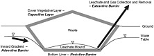
FIGURE 2.1 Schematic illustration of functional mechanisms for engineered barriers.
direction of its origin (e.g., release of stored water from soil covers by evapotranspiration). The use of zeolites in barriers for radioactive waste is an example of a capacitive barrier that also relies on other mechanisms to reduce contaminant transport: the zeolites retain the radioactive isotopes while radioactive decay processes reduce their potential impacts.
Advective barriers rely on advective flow to control the migration of contaminant transport media. In an advective barrier, gradients are introduced to generate a flow counter to the indigenous direction of contaminant transport. An example is a groundwater pumping system surrounding the waste that creates an inward gradient so that liquid flows into and not out of the system (Figure 2.1). Advective barriers also include pneumatic barriers, where a suction pressure is applied to control landfill gas transport.
Extractive barriers are used in conjunction with advective transport to remove contaminated liquid or gas for treatment and/or disposal. Examples are leachate and gas collection and removal systems that remove contaminated liquid and gas from inside the barrier system (Figure 2.1). Extractive barriers include extraction wells, trenches, and blanket leachate collector systems.
2.2.2
Barrier System Orientations
Final covers are the most common type of engineered barrier system. They are used for both engineered containment systems and nonengineered contaminated sites and dumps to keep waste and contaminants in and to keep potentially infiltrating water out. Most are resistive barriers, and many incorporate capacitive and extractive barriers to control surface water infiltration (Table 2.2). Enhanced capacitive covers, also referred to as alternative covers because they can
TABLE 2.2 Orientation, Components, and Functional Mechanisms of Engineered Barrier Systems
be substituted (with regulatory approval) for cover systems prescribed by regulation (i.e., composite or compacted clay covers), rely on evaporation and transpiration to control infiltrating surface water. They are becoming more common in arid or semiarid regions where potential evapotranspiration significantly exceeds actual precipitation (Shackelford, 2005).
Bottom barrier systems are used in landfills, surface impoundments, and other containment systems to hold waste and contaminants and to facilitate collection and removal of contaminated liquids. Basal liner systems for landfills are the most common bottom barrier system. Landfill basal liner systems are typically composed of several different components, including protection layers, liquid collection and removal systems, resistive barrier layers (liners), and diffusion attenuation layers. They generally employ a combination of mechanisms, including extraction, resistance, capacitance, and sometimes advection and reaction. Extractive bottom barriers (e.g., horizontal leachate collection wells) are also occasionally installed as remediation systems for contaminated sites. Resistive bottom barriers have also been proposed as remediation measures, but they are not commonly used because of practical difficulties associated with installing a continuous barrier beneath an existing contaminated site.
Lateral barrier systems are used to enclose wastes and provide barriers to groundwater flow or to facilitate removal of groundwater. They include side slope liner systems for landfills, vertical barrier walls, interceptor and extraction trenches, vertical extraction well systems, and vertical advective barriers. Side slope liner systems for landfills work in much the same way as landfill basal liner systems and rely on similar mechanisms and employ similar components. Vertical barrier wall systems are generally resistive barriers but may also include extractive components (e.g., extraction wells inside the barrier) or capacitive/reactive and advective mechanisms to supplement their resistance to contaminant transport. Extractive and injection lateral barrier systems, including vertical wells and trenches filled with granular materials, are used to control advective transport of liquid and gas in the subsurface. Extractive barriers, including vertical walls and extraction trenches, are usually accompanied by treatment and/or disposal of the extracted liquid and/or gas. The most common type of injection barrier is a vertical well into which air is injected to control the migration of gas in the vadose zone. Vertical liquid injection trenches can be used to create hydraulic gradients counter to the direction of contaminant transport. Injection barriers are often used in conjunction with some type of source control (e.g., gas or groundwater extraction) to limit the operating period of these systems. Vertical barrier walls and extraction trenches are commonly an integral part of systems used to isolate and contain waste and contaminated ground at previously uncontrolled disposal sites, many of which have been designated for remediation under the Superfund program.
2.2.3
Barrier Components
Common components of engineered barrier systems are listed in Table 2.2. These components can be classified broadly as soils, aggregates, cementitious and bituminous materials, and geosynthetics. Geomembrane liners (Box 2.1) and low-permeability soil liners, which both serve as resistive barriers, are common components in engineered barriers and
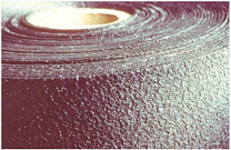
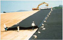
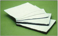

are frequently placed together to form a composite liner. Soil liners, often referred to as compacted clay liners, are generally made from fine-grained silts and clays or admixtures of coarse-grained soils with bentonite. The soil is compacted in 150-mm-thick lifts with a kneading action to form layers that are typically between 0.3 and 0.9 m thick. Alternatives to low-permeability soil liners include geosynthetic clay liners and Portland cement concrete or asphalt cement concrete, in which a granular soil aggregate is bound with cement or asphalt into a low-permeability layer that is 0.15 to 0.3 m thick. Portland cement concrete layers are commonly used to store hazardous and radioactive wastes until the radioactivity has decayed to levels that meet waste disposal criteria (10 CFR 61), prior to transport to permanent waste disposal sites. Asphaltic cement concrete layers have been used in cover and liner systems for long-term containment of radioactive wastes and in more conventional landfills.
Resistive barrier components in vertical walls include soil bentonite, cement bentonite, soil-cement-bentonite, steel or polymeric sheet piles, and geomembrane panels. These materials may be placed in a trench in a continuous mass or in interlocking panels or overlapping columns. The depth of installation depends on the type of vertical wall and the method of installation (EPA, 1998): a maximum of approximately 30 m for jet-grouted and soil-cement column walls, 25 m for soil-bentonite and cement-bentonite walls excavated with a backhoe,1 and 15 m for geomembrane panel and sheet pile walls.
Blanket drainage systems, including granular and geosynthetic drainage layers and horizontal and vertical wells,
are typically employed for liquid and gas removal (i.e., extractive control) and injection (i.e., for advective control). Capacitive barrier components are generally simple soil layers, sometimes enhanced by the addition of reactive or sorptive substances. Barrier components often include layers to protect against (1) mechanical distress or intrusion, such as puncture or tearing of resistive barriers; (2) erosion of final covers; and (3) clogging or mechanical penetration and disruption of drainage systems. Typical protective layers include soil, cobbles, or select waste mechanical buffers, and graded soil or geotextile filters and cushions.
2.2.4
Typical Engineered Barrier System Configurations for Landfills
Regulations often dictate the configuration of engineered barrier systems. Configurations that follow prescriptive minimum standards for bottom barriers and cover systems are illustrated in Figures 2.2 and 2.3, respectively. Figure 2.2a illustrates a bottom barrier system for municipal solid waste (MSW) landfills. The minimum prescriptive barrier system for an MSW landfill is a composite liner system composed of a 1- to 2-mm-thick geomembrane underlain by a 0.6-m-thick low-permeability soil layer and overlain by a 0.3-m-thick granular drainage layer with a minimum saturated hydraulic conductivity of 1 × 10⁻⁴ m/s. This layer comprises the leachate collection and removal system and is used to collect and remove the leachate from above the composite liner system. Barrier components that provide equivalent environmental protection to the prescribed components may be employed in practice. These include substitution of geosynthetic clay liners for low-permeability soil layers and substitution of geosynthetic drainage layers for granular drainage layers. Some existing MSW landfills have single-barrier layers with extraction (drainage) layers on top, but due to their potential for higher leakage potential in comparison with composite liners, they are not generally allowed for new construction. Some jurisdictions require double-liner systems for MSW landfills, with two separate resistive barrier layers overlain by extraction layers.
Figure 2.2b shows a bottom barrier system for hazardous waste landfills. The prescriptive minimum standard for the barrier system is generally a double liner with a single geomembrane primary liner over a drainage layer, over a geomembrane and low-permeability soil composite secondary liner system. A double composite liner system (i.e., a barrier system with two stacked composite liners) is used in many hazardous landfills to provide better protection against leakage than is achievable with a single composite liner. The extraction layer of the underlying composite liner is referred to as the leak detection system because monitoring of this layer provides a quantitative measurement of the leakage through the primary (upper) liner system.
Figure 2.3a shows a final cover system for MSW landfills according to RCRA Subtitle D. The prescriptive minimum barrier is a single 0.45-m-thick low-permeability soil barrier layer with a saturated hydraulic conductivity no greater than 1 × 10⁻⁵ cm/s, overlain by at least 0.15 m of vegetated cover soil for protection and underlain by a prepared foundation layer. However, Subtitle D also requires that the permeability of the final cover be less than that of any engineered bottom barrier or natural geological formation. This requirement is generally implemented by placing a geomembrane on top of the low-permeability soil layer in the cover of any landfill that has a geomembrane in the base liner system. Typical alternatives to the minimum prescriptive cover systems for MSW landfills include a 0.3-m-thick low-permeability soil barrier layer with a saturated hydraulic conductivity no greater than 1 × 10⁻⁶ cm/s (the California prescriptive minimum) or a geosynthetic clay liner or geomembrane used in lieu of the low-permeability soil layer. A drainage layer is often placed on top of the barrier layer and the overlying protection layer is frequently 0.3 m thick or more. In addition to these resistive barrier alternatives, capacitive evapotranspirative
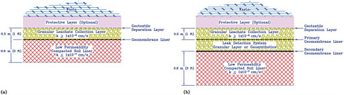
FIGURE 2.2 Prescriptive minimum bottom barrier system for (a) municipal solid waste landfills and (b) hazardous waste landfills under RCRA regulations in 40 CFR §264 and §258, respectively. The protective layer between the waste and the geotextile separation layer is typical but is not part of the prescriptive standard.
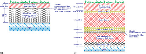
FIGURE 2.3 Prescriptive minimum final cover system for (a) municipal solid waste landfills and (b) hazardous waste and low-level radioactive waste landfills under RCRA 40 CFR §258.
final covers are increasingly being used as alternative cover systems in locations with arid and semiarid climates, where the performance of low-permeability soil barrier layers is in doubt because of the potential for desiccation cracking.
Figure 2.3b illustrates a final cover system for hazardous waste and low-level radioactive waste landfills. To limit infiltration to the greatest possible extent, a composite barrier is employed that generally consists of a geomembrane underlain by a 0.6-m-thick low-permeability soil layer with a saturated hydraulic conductivity no greater than 1 × 10⁻⁶ cm/s and overlain by a 0.3-m-thick granular drainage layer. A biotic barrier—a layer of rock or other mechanically resistant material—may be used to prevent inadvertent human and animal intrusion. The cover systems of low-level radioactive waste landfills may include thicker foundation and protective soil layers than those used in hazardous waste landfills.
The prescriptive final cover system for a site regulated under RCRA Subtitle C is a composite cover barrier with a biotic barrier, similar to that shown in Figure 2.3b. This type of final cover is sometimes referred to as a RCRA cap. RCRA caps may be used in conjunction with lateral barriers such as vertical barrier walls and extraction or injection trenches or wells to control lateral migration of contaminated groundwater or volatilized contaminants or lateral infiltration of groundwater. Although many uncontrolled waste sites are remediated under CERCLA or state-run programs and require a feasibility study to establish an appropriate cover system, RCRA caps are frequently employed at these sites.
2.2.5
Alternatives to Prescriptive Requirements
Prescriptive designs provide a good initial basis for landfill design and work well in many situations. However, landfills and other containment systems logically should be designed on a site-specific basis, taking into account the landfill size and nature of the waste, the operating environment (e.g., different designs might be needed for bioreactor landfills and conventional landfills; Rowe, 2005), and the local climate and hydrogeology. Alternative designs that require less engineering than prescriptive designs can be justified in certain circumstances. Under other circumstances, the prescriptive design may not be adequate and a higher level of engineering is required to provide adequate long-term environmental protection. It should be noted that simply meeting prescriptive standards does not relieve the design engineers of legal liability if the prescriptive design proves not to provide adequate environmental protection (see Estrin and Rowe, 1995, 1997, for a discussion of some of the legal issues related to design).
2.3
LIFE CYCLE OF A LANDFILL
Landfills are typically developed as a set of contiguous cells over a period of one or more decades. The life cycle of a cell begins with the initial construction of its base barrier system. Good construction quality control and quality assurance are critical at this stage to minimize subsequent leakage through the barrier system. The three stages following construction of the barrier system are (1) the initial period, (2) the active period, and (3) the postclosure period. During the first few months of landfilling (Stage 1), there is generally not enough waste in a cell to significantly control the flow of rainwater or snowmelt into the leachate collection system. The leachate collection system flow rates can be quite high (relative to later stages) after significant rainfall events. During the active period, waste is placed and covered with daily and intermediate layers of soil. Precipitation percolates through the waste and cover soils, which absorb and release some of the moisture at slower rates than the infiltration rate. Consequently, flow rates in the leachate collection system(s)
decrease as the cells fill and eventually stabilize. At closure of the cell, a cover is placed, which will substantially reduce the percolation of moisture into the waste and further dampen the effects of rainfall events. As a result, flow rates in the leachate collection system(s) decline further.
These three stages are common to all landfills. Municipal solid waste landfills also include stages related to the decomposition of waste and biological processes in the leachate collection system. Hence, leachate composition varies with time. Periods of heavy precipitation can dilute the leachate, especially after new sections of the leachate collection system have been constructed. Transport of leachate in a waste mass can be affected by settlement of wastes caused by decomposition and mechanical stress. The residence time of leachate in the waste mass can increase and flow of leachate into a collection system can decrease due to increased waste density.
The processes that occur in municipal landfills are reasonably well understood (e.g., Reinhart and Townsend, 1998). Concentrations of inorganic contaminants (e.g., chloride), largely unaffected by biological and chemical interactions, increase in the leachate over periods of up to several decades (Rowe, 2005) but eventually level off and then decrease because of dilution. Contaminants like calcium and volatile fatty acids reach a peak concentration in the leachate much earlier than chloride and then decrease because of waste biodegradation processes and biological activity in the leachate collection system (Rowe, 2005). Biodegradation of volatile fatty acids produces landfill gases (mostly methane and carbon dioxide), increases the pH of the leachate, and causes a number of inorganic contaminants (e.g., calcium, heavy metals) to precipitate (Rittman et al., 1996; Jefferis and Bath, 1999). In addition, when leachate enters a leachate collection system that is at or near atmospheric pressure, there may also be a substantial decrease in pCO2, which can lead to additional calcite precipitation in the collection system. The precipitates can clog leachate collection systems and also substantially reduce the concentrations observed in leachate pumped out of the landfill. Thus, the processes that occur in the leachate collection system have both advantages and disadvantages. On the negative side, they cause clogging, which reduces the hydraulic conductivity and hence, potentially, the flow. On the positive side, they treat (“clean up”) the leachate by immobilizing a significant fraction of ions like calcium and some heavy metals and by reducing the concentrations of organic contaminants (e.g., volatile organic compounds, volatile fatty acids) in the collected leachate. As a consequence, the leachate that is collected is not necessarily representative of what may leak through liners. The concentration of contaminants available to leak or diffuse through the liner may be higher than what is observed in the collected leachate (Rowe, 2005).
Degradation of organic waste in MSW landfills generates gas and heat, which can increase the temperature both on the base liner and in the cover and adversely affect the barrier components (Rowe, 2005; Yesiller et al., 2005). Aerobic degradation of organic wastes produces primarily carbon dioxide, while anaerobic degradation produces 40 to 45 percent methane and traces of other volatile and semivolatile organic compounds. Aerobic degradation generates water, while anaerobic degradation consumes water. The gas generated by anaerobic degradation contains roughly similar amounts of methane and carbon dioxide, minor amounts of nitrogen and a few other compounds, and trace amounts of volatile organic compounds. Semivolatile compounds are not easily volatilized and thus are not present in meaningful concentrations. The gas may condense and form a contaminated liquid (e.g., an acidic liquid with small amounts of volatile organic compounds). Some can also dissolve in leachate. Waste placed in an MSW landfill generally degrades aerobically until the oxygen trapped in the pores is consumed; then anaerobic degradation begins. However, improperly operated landfill gas systems and poor daily cover practices can lead to the introduction of additional oxygen to the waste and sustained aerobic degradation. Sustained aerobic degradation produces higher temperatures than anaerobic degradation. Gas generation in MSW landfills, whether aerobic or anaerobic, generally increases steadily during the active life of the landfill, peaks at or near the time when the last waste is placed in the landfill, and then decreases with time during the closure period. How long significant quantities of gas are generated depends to a large extent on the local climate and operational practices. With sufficient liquid, anaerobic degradation may be essentially complete in decades. In an arid climate, on the other hand, anaerobic degradation may continue at a slow rate for hundreds of years. Therefore, a final cover that limits infiltration can actually extend the period over which decomposition processes are active in MSW landfills.
Occasionally, water or oxygen is intentionally introduced during the active life of MSW landfills to accelerate anaerobic or aerobic degradation, respectively. One of the objectives of these bioreactor landfills is to reduce the period during which the waste remains active by accelerating stabilization of the waste and reducing potential long-term environmental liability.2 However, bioreactor landfills remain an experimental technology because many issues have not yet been resolved (e.g., the effect of extra heat on the service life of the liner, the effect of additional heat and leachate on the long-term performance of the leachate collection system).
MSW landfill temperatures typically increase gradually over time, then peak and ultimately decrease as degradation tapers off. The time-temperature history is linked to biological activity in the waste and hence in most cases to gas production. Both gas production and temperature can be increased by addition of moisture to the waste. Although organic matter may be degraded relatively quickly,
|
2 |
Technical information on bioreactor facilities can be found on websites such as <http://www.epa.gov/epaoswer/non-hw/municipal/landfill/bioreactors.htm>, <http://www.wm.com/WM/environmental/Bioreactor/index.asp>, and <http://www.itrcweb.org>. |
contaminants will likely continue to be released for decades to centuries because of their slow release through garbage bags and the slow degradation of waste such as cellulose. In addition, time-dependent sorption/desorption of contaminants from low-permeability soil layers in barriers may affect the release of contaminants to the environment. Overall, the period during which a large landfill will potentially release contaminants at unacceptably high levels may be on the order of hundreds of years for municipal solid wastes (Rowe et al., 2004). The threat can be mitigated through long-term cap maintenance to minimize the migration of liquid into the landfill. In the case of radioactive wastes, it may take hundreds to thousands of years (e.g., mill tailings, see NRC, 2002) before decay reduces radiation to preemplacement levels. Low-level radioactive waste landfills (e.g., Fernald, Ohio) are thus designed for a very long lifetime (i.e., 200 to 1,000 years; 40 CFR §192.02).§192.02).
Hazardous waste landfills are generally not subject to the same long-term biological and chemical processes as MSW landfills because hazardous waste is generally stabilized chemically prior to disposal. However, the life span of a hazardous waste landfill is generally assumed to be on the order of a hundred years or more. Nonengineered hazardous waste dumps and contaminated soil and groundwater sites subject to corrective action may have life spans on the order of tens to hundreds of years, depending on the source and nature of the contaminants. Low-level radioactive waste landfills may have life spans on the order of hundreds of years up to a thousand years, depending on the rate of radioactive decay (GAO, 2005; NRC, 2006).


