
4
Performance of Barrier System Components
The performance of a barrier system component depends on two factors: (1) the performance of the component itself and (2) the way individual components interact as a system to contain contaminant transport. This chapter focuses on observations and predictions of the performance of individual barrier system components. Component interaction and overall barrier system performance are discussed in Chapter 5.
Problems that may arise with the performance of barrier system components in the short, medium, and long terms (see definitions in Box 1.2) are summarized in Table 4.1.
4.1
EARTHEN BARRIERS
Processed natural soils and mineral admixtures such as bentonite are extensively used as components of liners, covers, and vertical barrier walls in waste containment systems. At some sites the natural soil layer underlying a waste landfill or contaminated ground may be relied on to isolate and/or absorb contaminants in an engineered barrier system. If geological conditions and testing indicate that such layers are suitable in their initial state, they may still be subject to the same types of long-term performance concerns as earthen layers within liners and covers, including secondary structure development, incompatibility with the waste, and defects arising from induced deformations. Key performance concerns for earthen barriers, such as compacted clay liners, include the following:
-
Short term: the ability to achieve the specified hydraulic conductivity upon construction in the field and slope stability.
-
Medium and long term: increases in hydraulic conductivity with time caused by desiccation, shrink/swell, freeze/thaw, root penetration, thermal stresses, differential settlement, or chemical incompatibility; erosion of protective soil layers, development of secondary structures from cracking; and waste and slope stability.
Observations and predictions associated with these performance considerations are discussed below.
4.1.1
Hydraulic Conductivity
Field performance data on as-constructed compacted clay liners are summarized by Benson and Boutwell (1992), Daniel (1984, 1990), Cartwright and Krapac (1990), Elsbury et al. (1990), Gordon et al. (1990), Johnson et al. (1990), Reades et al. (1989), Trautwein and Williams (1990), King et al. (1993), Benson et al. (1999), Rowe et al. (2000), and Rowe (2005), among others. Reliable field permeability measurements generally require use of relatively large-scale tests, such as sealed double-ring infiltrometer tests or back calculation from lysimeter performance, to account for potential development of secondary structures within the compacted clay. An example of the measurement of the hydraulic conductivity of a compacted clay liner in the field using a sealed double-ring infiltrometer is given in Box 4.1. Available field performance data indicate that a target saturated hydraulic conductivity value (e.g., the prescriptive value of 1 × 10⁻⁹ m/s for Subtitle D low-permeability liner systems) can generally be achieved at the end of construction if the soil is compacted wet of the optimum moisture content and proper construction procedures are used.
Hydraulic conductivity data on compacted clay low-permeability soil layers for 85 cases from active landfill cells (8) and test pads (77) were reported by Benson et al. (1999). All of the compacted clay layers were intended to achieve a saturated hydraulic conductivity of less than 1 × 10⁻⁹ m/s. Although the test results indicated that the low-permeability soil layers for all 8 of the active landfill cells achieved a saturated hydraulic conductivity of less than 1 × 10⁻⁹ m/s (as measured by lysimeters), 22 of the 77 test pads tested did not achieve that goal, despite the fact that in all but 3 cases laboratory testing on thin-walled tube samples recovered from the test pad yielded a saturated hydraulic conductivity of less than 1 × 10⁻⁹ m/s.
TABLE 4.1 Performance Concerns for Barrier System Components
Relatively good agreement was achieved between hydraulic conductivities measured in the field using lysimeters (underdrains) and sealed double-ring infiltrometers, with geometric means of 9 × 10⁻¹¹ m/s (8 cases) and 5 × 10⁻¹⁰ m/s (77 cases), respectively. However, the field-measured hydraulic conductivities did not correlate well with laboratory values of hydraulic conductivity measured on samples recovered from the test pad using thin-walled tubes when the soils were compacted dry of the optimum moisture content. This result reaffirms the need to compact clay liners wet of the optimum moisture content. Provided that this criteria is met and that there are no obvious visible secondary features (e.g., desiccation cracks), experience has shown that the hydraulic conductivity obtained in the laboratory on samples recovered with thin-walled tubes correlates well with values obtained in the field using lysimeters (e.g., Rowe et al., 2004).
Direct measurements of field hydraulic conductivity using sealed double-ring infiltrometers, as described in Box 4.1, are generally made only on test pads to establish compaction procedures and index properties (e.g., compaction moisture content and density) for quality control of the actual liner. Although the majority of field hydraulic conductivity measurements on compacted clay liners are made during or just after the completion of liner construction, some data are available on the hydraulic conductivity of a liner in the medium term. Box 4.2 describes the performance of a compacted clay liner test section subject to a constant hydraulic head of 0.3 m over a 14-year period. The performance of a liner in a waste containment environment may be influenced by the effects of increased temperatures, accompanying waste decomposition, and overburden pressures, as illustrated by the case history in Box 4.3.
4.1.2
Secondary Features
The difference between laboratory- and field-measured saturated hydraulic conductivity values for compacted earthen barriers can be attributed to macrostructure that often occurs when the soil is compacted at or dry of the optimum moisture content (Benson et al., 1999). Secondary features
|
BOX 4.1 Case History on Measuring Field Performance of Compacted Clay Liner This case history illustrates the use of hydraulic conductivity measurements in the field to demonstrate the short-term performance of a compacted clay liner. The field data come from a test pad constructed to evaluate a compacted clay liner for a proposed hazardous waste landfill near Phoenix, Arizona (Gilbert, unpublished). The compacted clay liner was a soil-bentonite admixture, and the test method was a sealed double-ring infiltrometer (Daniel, 1989; ASTM D 3385-88). A 1.5-m square “ring” was placed on top of the liner and filled with water to a depth of 0.3 m. The infiltration rate (the volumetric rate of flow per unit area seeping into the top of the clay liner under a constant head) was measured by tracking the mass of water lost from the ring as a function of time. The infiltration rate in Figure 4.1 was calculated assuming that all of the water lost was infiltrated down into the clay liner. Tensiometers in the clay liner at depths of 0.15, 0.3, and 0.45 m were used to track the change in matric suction, and therefore pore water pressure, with depth and time as the water infiltrated the liner. When the measured matric suction is zero in a tensiometer, the hydraulic gradient can be estimated by assuming the pore water pressure is equal to zero at the elevation of the tip of the tensiometer. The infiltration rate, q, is related to the hydraulic conductivity as follows: q = ki, where k is the hydraulic conductivity and i is the hydraulic gradient. Hence, the hydraulic conductivity in Figure 4.1 is calculated by dividing the infiltration rate by the estimated gradient. The calculated or “measured” hydraulic conductivity changes with time for several reasons: (1) the soil swells during the test, so some of the flow lost from the inner ring goes into storage and does not infiltrate through the clay liner; (2) the depth of soil used to estimate the hydraulic conductivity increases with time and the soil displays variability with depth (such as layering); and (3) the hydraulic gradient changes rapidly with time and is more difficult to estimate at the beginning of the test. The reported value is typically taken from the last reading, a hydraulic conductivity between 2 × 10⁻¹⁰ and 3 × 10⁻¹⁰ m/s in this case. Note that this hydraulic conductivity does not necessarily correspond to saturated conditions because of the possible existence of entrapped air, but the measured value probably corresponds reasonably well to the field value since the test conditions are similar to those expected in the field except for the lack of overburden stress on the clay liner. In the field application the applied stress from waste in the actual landfill will tend to increase the degree of saturation and reduce the saturated hydraulic conductivity due to consolidation. The saturated hydraulic conductivity was measured in the laboratory on small-scale (64-mm-diameter), thin-walled tube samples taken from the clay liner at the end of construction. The laboratory measurements, which correspond to saturated conditions, ranged from 1 × 10⁻¹⁰ m/s to 7 × 10⁻¹⁰ m/s with a geometric mean of 3 × 10⁻¹⁰ m/s. Therefore, in this case, the hydraulic conductivity measured at the field scale (a 1.5-m square area), between 2 × 10⁻¹⁰ and 3 × 10⁻¹⁰ m/s, was both comparable to the laboratory measurements on small-scale samples under saturated conditions and less than the regulatory-specified maximum of 1 × 10⁻⁹ m/s. 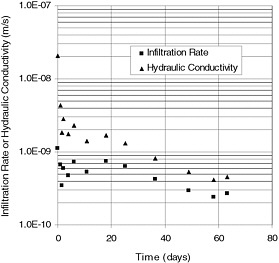 FIGURE 4.1 Field data from sealed double-ring infiltrometer test on a compacted clay liner. |
|
BOX 4.2 Case History on Field Performance of a Compacted Clay Liner This case history documents the monitoring of an instrumented earthen liner for changes in hydraulic conductivity over 14 years. In 1987 a heavily instrumented earthen liner was constructed by the Illinois State Geological Survey in Champaign, Illinois. The liner had dimensions of 7.3 m × 14.6 m × 0.9 m and was impounded with 0.3 m of water for 14 years. Two years after construction a hydraulic conductivity of 3–4 × 10⁻¹⁰ m/s was measured using large- and small-ring infiltrometers (Cartwright and Krapac, 1990). The liner was originally compacted to a mean gravimetric water content of 11.6 ± 1.2 percent, a dry density of 1.83 ± 0.071 kg/m3, and a saturation of 64.0 ± 9.6 percent (Frank et al., 2005). After 14 years of ponding, the water content remained relatively constant (10.6 ± 1.0 percent during excavation), even though water infiltration into the liner was documented. The essentially constant water content was attributed to insufficient hydraulic pressure to saturate the unsaturated portions of the liner. In contrast, the mean dry density of the liner increased approximately 10 percent by the conclusion of the test, and the saturation increased to 80.0 ± 6.3 percent. Tracer studies and modeling performed at the conclusion of the test indicated that the advective transport of tracers through the liner was negligible, with model results yielding k ≤ 1 × 10⁻⁹ m/s (Willingham et al., 2004). |
|
BOX 4.3 Case History on Long-Term Field Hydraulic Conductivity Changes Resulting from Consolidation and Heating This case history illustrates how the hydraulic conductivity of a clay layer in a bottom liner system in a municipal solid waste landfill can decrease over time because of consolidation but also increase over time (to a lesser extent) because of increased liner temperature. The Keele Valley Landfill, located in Maple, Canada, covers 99 hectares. The barrier system typically consists of a 1.5-m-thick compacted clay liner overlain by a 0.3-m-thick sand protection layer and a leachate collection system (described in Box 4.4). The landfill capacity is approximately 33 million m3, and the maximum depth of waste at closure was about 65 m. Between the first acceptance of waste in 1984 and closure in December 2002, the landfill received 28 million tonnes of municipal solid waste. The landfill has been extensively monitored and studied (Rowe, 2005). The hydraulic conductivity of the compacted clay liner was monitored by means of several lysimeters below the liner. Consolidation was an important factor affecting changes in the hydraulic conductivity k with time. For example, at 1 lysimeter the waste thickness increased from 1 m in November 1984 to 33 m in April 1987, then remained relatively constant. The annual average k of the liner dropped from 4 × 10⁻¹⁰ m/s in 1984 to 3.1 × 10⁻¹¹ m/s in 1991. Two consolidation-related factors could have affected flow to the lysimeter during this period. First, expulsion of water from voids during consolidation is not explicitly considered in calculating k, so the inferred k value will be higher than the actual value until consolidation is complete. This effect was greatest from 1984 to 1987 when the waste thickness increased. Second, the decrease in void ratio of the soil due to consolidation will result in a decrease in k with time. Both effects occurred relatively quickly in the liner since consolidation was fast (95 percent consolidation in less than a year for a given load increment), but the decrease in void ratio was the dominant factor (Rowe, 2005). Hydraulic conductivity of the compacted clay liner was also influenced by temperature. The temperature above the compacted clay liner was monitored at four locations over a 21-year period (Barone et al., 2000; Rowe, 2005). At one location the average annual temperature above the liner increased from 14°C in 1991 to 35°C in 1995, after which time the temperature remained constant (see Box 5.3 for the relationship between temperature and the performance of the overlying leachate collection system). Over the same period, the average annual hydraulic conductivity at this location increased from 3 × 10⁻¹¹ m/s to 5 × 10⁻¹¹ m/s. This increase matches what would be expected from theoretical consideration of the effect of temperature on the viscosity and density of the leachate. Since both the temperature and the hydraulic conductivity have stabilized, no significant effect of clay-leachate interaction over the subsequent 8 years is likely (Rowe et al., 2004). |
such as cracks and voids can degrade the performance of both compacted earthen barriers and natural clay layers, where secondary features such as fissures are known to have a significant impact on performance (e.g., Keller et al., 1986; Rowe et al., 2000). Stress relief from differential settlement in soil covers can create secondary zones of high permeability, even in the absence of detectable cracking. The development of secondary features in a clay barrier as a result of desiccation, freeze/thaw damage, or tensile strains can cause significant increases in hydraulic conductivity. This effect is a particular concern for cover systems and for clay liners that are left uncovered during and after construction. Field data on air desiccation and freeze/thaw damage have been reported by Montgomery and Parsons (1990), Benson and Othman (1993), Corser and Cranston (1991), Benson and Khire (1995, 1997), Melchior (1997), Albrecht and Benson (2002), and Albright et al. (2006).
Desiccation of compacted clay liners in cover systems has been reported to result from both drying and freezing (Benson and Khire, 1997; Benson, 1999; Albrecht and Benson, 2002; Albright et al., 2006). Test pits excavated in compacted clay liners 6 months and 3 years after construction showed
extensive cracking in a profile with a single compacted clay liner.
Desiccation of compacted clay liners in bottom barrier systems is also possible if the liners are left uncovered (or covered only by a geomembrane) for weeks or months after construction (Corser and Cranston, 1991). Heat generated in the waste may also cause desiccation over the long term. The potential for desiccation depends on the temperature gradient, the water retention curve of the soil below the clay liner, and the location of the water table (Rowe, 2005). For example, a test plot of a barrier system with a geomembrane overlying a compacted clay liner was subjected to a constant temperature of 40°C above the liner system and an overburden stress of approximately 40 kPa for 2.5 years (August et al., 1997). The compacted clay liner was underlain by a fine-grained soil in one section and a coarse-grained soil in another section. The water content of the section over the fine-grained soil remained relatively constant with maximum changes of less than 1 percent, whereas the water content of the section over the coarse-grained soil decreased up to 7 percent under thermal gradients as low as 5°C/m. Additional studies of desiccation of clay liners in composite liner systems caused by the heat from decomposing waste are reported by Rowe (2005).
4.1.3
Chemical Compatibility
The long-term performance of earthen barriers with respect to advective flow depends directly on the hydraulic conductivity of the soil barrier materials after saturation by the liquid being contained, which for liner systems is typically leachate rather than water. It is important to know, therefore, whether or not the barrier soil and permeating liquid are compatible so that permeation with the liquid causes no significant increase in hydraulic conductivity relative to that based on permeation with water (Fernandez and Quigley, 1985, 1988; Bowders et al., 1986; Bowders and Daniel, 1987; Shackelford, 1994; Shackelford et al., 2000; Rowe et al., 2004; Lee et al., 2005). Chemical incompatibility may create adverse effects both by increasing the saturated hydraulic conductivity of the soil and by creating secondary features that increase the mass saturated hydraulic conductivity (e.g., by inducing cracking due to shrinkage or embrittlement of the clay). An adverse interaction due to chemical incompatibility is a particularly important consideration when clay soils are used for waste containment, since an adverse interaction may result in an increase in saturated hydraulic conductivity and potentially unacceptable release rates of contaminants into the surrounding environment. The importance of compatibility testing is highlighted in the industry standard ASTM D 7100.
Most, if not all, of the available data on chemical compatibility of compacted clay liners or other earthen barriers are based on the results of laboratory tests, performed either as part of the design process for the waste containment facility or as research studies. Field data on chemical compatibility are not readily available for several reasons, including (1) less control inherent in field tests, especially when dealing with potentially harmful liquids; (2) lack of evidence of chemical incompatibility in waste containment facilities that are performing satisfactorily; and (3) years or even decades may be required before there is any evidence of chemical incompatibility processes that lead to volume change and cracking (Shackelford, 2005).
Numerous studies performed primarily to evaluate factors that potentially influence chemical compatibility of earthen soils used as barriers have provided some insight into expected behavior (e.g., Anderson and Jones, 1983; Fernandez and Quigley, 1985, 1988; Griffin and Roy, 1985; Mitchell and Madsen, 1987; Goldman et al., 1988; Shackelford, 1994; Stern and Shackelford, 1998). In general, the results indicate that qualitative predictions of chemical incompatibility can be made based primarily on three considerations: (1) the type and properties of the liquid, (2) the type and properties of the soil, and (3) the physical conditions imposed on the barrier soil.
The higher the concentration and/or the charge of ions in inorganic solutions, the greater the possibility for chemical incompatibility. In addition, decreasing pH tends to increase the potential for chemical incompatibility in two ways. First, as pH decreases, the concentration of ionic species in solution tends to increase. Second, solutions with pH less than about 2 can dissolve clay soils, resulting in the development of relatively large pores that cause increases in hydraulic conductivity (Shackelford, 1994). Very high pH (>12) solutions may also dissolve silica, although no examples of such solutions causing compatibility problems in compacted earthen liners have been published. Finally, high concentrations of hydrophilic organic compounds and pure-phase organic liquids (i.e., light and dense nonaqueous-phase liquids) can cause incompatibility due to clay shrinkage when the dielectric constant of the liquid is significantly lower than it is for water (e.g., Mitchell and Madsen, 1987; Shackelford, 1994). However, the specific threshold values at which chemical incompatibility becomes a potential issue for each of these parameters will also depend on the type and properties of the soil and the physical conditions imposed on the barrier soil.
The potential for incompatibility generally increases as the activity, defined as the plasticity index divided by the percent of clay-size particles (<2 µm), of the soil increases (Shackelford, 1994). The activity reflects both the mineralogy of the soil, with higher values for a plasticity index correlating with higher contents of high-activity clay minerals, such as sodium smectite, as well as the surface area effects, with greater surface areas reflected by higher contents of the smaller, clay-sized particles. Fortunately, available evidence suggests that many, if not most, natural clay soils used as compacted clay liners have relatively low plasticity index values. For example, of the 85 compacted clay liners
evaluated by Benson et al. (1999), 49 were constructed using clays of low plasticity (ASTM D 2487), with the remainder exhibiting moderate rather than high plasticity index values (maximum of 71 compared with >300 for bentonite). Consequently, waste containment barriers that contain significant bentonite contents, such as compacted sand-bentonite and soil-bentonite liners, soil-bentonite backfills for vertical cutoff walls, and geosynthetic clay liners (GCLs) may be particularly susceptible to chemical attack by invading liquids, resulting in chemical incompatibility and increased hydraulic conductivity.
Three factors relating to the physical conditions are particularly important: (1) the stresses imposed on the barrier soil (Fernandez and Quigley, 1991; Shackelford et al., 2000; Lee et al., 2005), (2) the initial level or degree of hydration of the barrier soil (e.g., Shan and Daniel, 1991; Daniel et al., 1993; Shackelford, 1994; Didier and Comeaga, 1997; Gleason et al., 1997; Kajita, 1997; Petrov and Rowe, 1997; Petrov et al., 1997a; Quaranta et al., 1997; Ruhl and Daniel, 1997; Stern and Shackelford, 1998; Lin and Benson, 2000; Shackelford et al., 2000; Vasko et al., 2001; Ashmawy et al., 2002; Shan and Lai, 2002), and (3) the hydraulic gradient of the liquid across the barrier (Shackelford, 1994). In general, the higher the effective stress in the soil, the less susceptible the soil is to adverse consequences of chemical attack. Thus, consolidation of barrier soils (e.g., from the weight of the overlying waste) not only tends to decrease the hydraulic conductivity of the barrier soil but also reduce the potential for chemical incompatibility.
A higher initial degree of water saturation of the barrier soil prior to permeation with a chemical solution, commonly referred to as prehydration, also has been reported to provide increased resistance to increases in hydraulic conductivity. However, prehydration by continuous permeation results in a different degree of resistance to chemical attack than prehydration by capillary wetting. In addition, most of the studies reporting a significant prehydration effect have involved barrier soils either comprised of or containing high-activity sodium bentonite. Recent studies also indicate that the prehydration effect is concentration dependent and tends to diminish as the concentration of chemical species in solution decreases (Lee and Shackelford, 2005a). Lastly, much of the data supporting the claim of increased chemical resistance with increased prehydration has been criticized on the basis that the data were derived from hydraulic conductivity tests that were terminated before chemical equilibrium between the effluent and influent had been achieved (Petrov et al., 1997b; Shackelford et al., 2000).
Finally, two-phase flow, the migration of mixtures containing two separate liquid phases in soil, requires special consideration. The interaction between the two liquid phases is particularly important when nonpolar hydrophobic organic liquids migrate through a barrier soil at an initially high degree of water saturation, such as a compacted clay liner. Due to surface and interfacial tension effects, the non-polar liquid (a non-wetting fluid) can displace the water (a wetting fluid) in the pore space of the soil only after a minimum pressure (known as the entry pressure) for the non-wetting fluid is reached. Although some studies have shown that permeation of compacted clay soils by hydrophobic organic liquids has resulted in significant increases in hydraulic conductivity (e.g., Fernandez and Quigley, 1985), the hydraulic gradients required to force these liquids through the soils typically have been quite large (>100). Thus, the relevance of these results to situations where much smaller hydraulic gradients are applicable is questionable (Shackelford, 1994).
4.1.4
Chemical Transport
Chemicals migrate through earthen barriers primarily by two transport processes: advection and diffusion. A third process that causes spreading of the contaminant front due to variations in flow, referred to as mechanical dispersion, is typically insignificant in the case of thin, low-permeability earthen barriers and is consequently ignored. In addition to advection and diffusion, chemicals are subject to the myriad of physico-chemical processes (e.g., adsorption/desorption, precipitation/dissolution, acid/base, redox) and biological processes during migration that can ultimately affect the contaminant mass that flows through the barrier.
Temperature affects advective/diffusive transport as well as other physico-chemical and biological processes that contribute to contaminant mass transport. Hydraulic conductivity is expected to increase with temperature (see Section 4.1.2), which would increase advective transport. The free solution diffusion coefficient for species common in municipal solid waste (MSW) leachate (Rowe et al., 2004) and the soil diffusion coefficient for a clay soil beneath a landfill (Crooks and Quigley, 1984) increase with temperature, which would increase diffusive transport.
The advective mass flux of contaminants is essentially the product of the liquid flow or leakage rate and the contaminant concentration at a specified location and time. According to Darcy’s law, typical steady state leakage rates for an intact compacted low-permeability earthen barrier (e.g., a compacted soil layer with no secondary permeability features such as cracks or fissures) are shown in Table 4.2. These values do not take into account that both the gradient and the hydraulic conductivity may vary with time for reasons such as those discussed above.
The results of several field studies indicate that diffusion can be a significant, if not dominant, transport process for
TABLE 4.2 Representative Leakage Rates for Clay Liners
|
Hydraulic Conductivity (m/s) |
Steady State Leakage Ratea (lphd) |
|
1 × 10⁻⁹ |
100 to 10,000 |
|
1 × 10⁻¹⁰ |
10 to 1,000 |
|
1 × 10⁻¹¹ |
1 to 100 |
|
aFor typical range of hydraulic gradients from 1/10 to 10. |
|
chemicals through intact clayey tills and low-permeability compacted clay liners (Goodall and Quigley, 1977; Crooks and Quigley, 1984; Johnson et al., 1989; Toupiol et al., 2002; Willingham et al., 2004). For example, the results of a tritium and bromide tracer test conducted over 13 years on a 0.3-m-thick compacted clay liner demonstrate that diffusion was the dominant transport mechanism and that there was no apparent preferential flow (Box 4.2; Toupiol et al., 2002; Willingham et al., 2004). As a result of these and other studies, minimizing advective mass flux transport has long been recognized as a necessary, but not sufficient, condition for minimizing chemical transport through low-permeability earthen barriers (Shackelford, 1988).
However, in contrast to these studies, Munro et al. (1997) found that advection and mechanical dispersion were more important than diffusion for a case involving migration of landfill leachate from an unlined landfill located directly on a fractured clayey till. This result underscores the importance of two considerations in terms of minimizing the extent of chemical release from waste disposal sites, namely the importance of a low-permeability engineered barrier system and the importance of disposal site location. Furthermore, in those cases where diffusion dominates advection, the total chemical transport is likely to be relatively small compared to those cases where advection dominates.
Recently, volatile organic compounds at various concentrations have appeared in a number of samples from 91 large (~ 110 m2) collection lysimeters (underdrains) located beneath both composite and compacted clay liners at 38 Wisconsin landfills that have been in operation for about 10 to 20 years (Shackelford, 2005; Klett et al., 2006). For example, concentrations greater than allowable maximum contaminant levels for toluene, tetrahydrofuran, dichloromethane, benzene, and ethylbenzene have been found in 90 of the 1,200 samples (~ 8 percent) from cells with liners containing geomembranes (Benson and Edil, 2004). These observations were not anticipated because the liners in Wisconsin have traditionally been thicker than those required by Resource Conservation and Recovery Act (RCRA) Subtitle D for MSW disposal facilities (Federal Register, 1991). That is, prior to 1996, Wisconsin required landfill cells to be lined with a minimum of 1.5 m of compacted clay, compared to 0.91 m required by RCRA Subtitle D. Subsequent to 1996, both Wisconsin and RCRA have required a composite liner consisting of a geomembrane liner overlying compacted clay, but Wisconsin requires 1.2 m clay compared to 0.62 m required by RCRA. The effects of natural attenuation processes such as dilution, adsorption, and degradation likely will render concentrations of these volatile organic compounds below detectable levels by the time the contaminants reach a regulatory compliance point, such as a perimeter monitoring well (Benson and Edil, 2004). The performance record is still relatively short (~ 10 to 20 years), so continued monitoring of these and other landfills will be required over the longer term before any final conclusions can be drawn regarding the performance of modern waste containment systems.
4.1.5
Mechanical Performance Issues
The ability of an earthen barrier to serve its intended function can be affected by cracking, erosion, and slope stability. Although attention often focuses on the resistance of barriers to advective flux of liquids and diffusive flux of chemicals, earthen barrier layers may also serve as intrusion barriers, provide protection for other layers in the barrier system, and resist advective flux of gases.
Gas control is a persistent problem at municipal landfills with earthen cover systems. Frequent maintenance (i.e., reworking the cover in areas where monitoring indicates gas emissions exceed regulatory standards) is commonplace at landfills that produce gas. This need for frequent maintenance can be attributed in part to cracking induced by subsidence of the waste and in part due to desiccation (e.g., from freeze/thaw). Observations of the susceptibility of earthen covers to gas emission suggests that they may also be poor infiltration barriers because cracks that let gas out are likely to indicate secondary structure development that degrades the hydraulic conductivity of a cover barrier layer.
Erosion of the uppermost earthen layer in a barrier system can also be a persistent problem at sites with covers that are steeper than the surrounding stable landforms. Establishment of healthy vegetative cover and provision of a mechanically resistant erosion control layer can mitigate soil cover erosion. However, until a stable ecosystem that mimics stable regional landforms develops on the cover, continued maintenance is likely to be required for vegetative cover layers. The longevity of mechanical erosion control layers depends upon the steepness of the cover, the severity of erosion-inducing forces (e.g., wind, water, freezing, thawing), and the character of the erosion-resistant material.
The integrity of earthen barriers can also be affected by displacements associated with slope instability. Earthen barrier layers in liner systems can be disrupted by foundation instability that develops as the waste is placed and the load on the foundation increases. Earthen barrier layers in cover systems are susceptible to veneer instability, wherein a planar failure surface develops along one of the interfaces in the system. Soil-geomembrane interfaces may be particularly susceptible to veneer failure due to the reduced strength of the interface compared to the soil. Failures at drainage layer interfaces are also common due to clogging or inadequate capacity of the drainage layer and the associated buildup of pore pressures within the drainage layer.
4.1.6
Summary
Documented observations of the hydraulic performance of compacted clay barriers for more than about 15 years do
not exist. However, the hydraulic conductivity of clay barriers is generally acknowledged to be susceptible to significant increase as a result of processes such as desiccation cracking, differential settlement, lateral spreading (induced tension), freezing and thawing, and root penetration. These processes are most significant in cover systems because bottom barrier performance is generally enhanced by increases in the confining pressure associated with waste disposal. Earthen barriers are also susceptible to a variety of mechanical performance problems, including erosion and cracking of earthen cover systems, disruption of base liner barrier layers due to foundation instability, and veneer failure of cover barrier layers due to low interface strength, clogging, or inadequate capacity of drainage layers.
Both laboratory research and field observations suggest that the following conclusions can be drawn about the performance of earthen barriers:
-
Clay layers, as components of barrier systems, are generally effective in the short and medium term unless poor construction and/or operational practices diminish layer integrity.
-
Unprotected clay layers in covers may develop secondary permeability that can lead to decreased effectiveness.
-
Temperature effects and postconstruction moisture changes in earthen barriers used in bottom liner systems have received insufficient attention.
-
Laboratory data indicate that there may be circumstances (e.g., when dealing with active clays) where there is cause for concern about chemical compatibility effects within clay liners, but corroborating field data are lacking.
4.2
GEOMEMBRANES
Short-term performance concerns for geomembrane barriers include defective material, physical damage caused by construction activities, and defective seams. Medium- and long-term performance concerns include geomembrane puncture due to increased overburden pressure and global stability and local slope stability failures, as well as loss of integrity caused by degradation. Global and local stability are addressed in Chapter 5. Geomembrane degradation is generally considered to be a long-term performance issue. However, as discussed below, under some conditions geomembrane degradation may develop in the medium term.
Modern manufacturing and construction quality assurance (CQA) processes have improved the as-manufactured quality of geomembranes. However, geomembranes can be easily damaged during installation, which emphasizes the importance of continuous observation of liner construction until a sufficient buffer layer of soil or waste shields the geomembrane from construction equipment and other potential sources of damage (see Box 5.2).
4.2.1
Chemical Transport
Chemical transport through geomembranes occurs via two mechanisms (Rowe, 1998; Katsumi et al., 2001): (1) advective transport of chemicals via leakage through holes or defects in the geomembranes and (2) molecular diffusion through the intact geomembrane. Equations for calculating the rate of leakage through geomembrane defects were proposed initially by Giroud and Bonaparte (1989) and refined subsequently by other investigators. Measurements of flow rates through geomembranes are sparse, although monitoring of leak detection systems provides information on likely leakage levels (Bonaparte et al., 2002) and the equations that should be used to predict leakage (Rowe, 2005). Chemical transport flow rates have usually been estimated from laboratory studies aimed at assessment of the prediction capabilities of proposed transport equations (e.g., Benson et al., 1995; Rowe et al., 2004), rather than evaluation of the performance of geomembranes used in liner systems (although Rowe, 2005, reports monitoring in a clay liner below a geomembrane over a 12-year period). In lieu of field measurements of leakage through geomembranes, the general practice has been to either estimate (in design) or measure (during CQA) the number of holes or defects that occur per unit area in a geomembrane and then estimate the resulting leakage rate using predictive equations. The amount of leakage through a geomembrane will depend on the particular situation but in general will be proportional to the number of holes or defects in wrinkles in the geomembrane. With good construction, the chemical transport of organic compounds (especially volatile organic compounds) will be controlled by diffusion through the barrier, rather than by the number of holes (Rowe, 2005).
Diffusion of volatile organic compounds occurs through geomembranes, in both the aqueous phase (e.g., Rowe et al., 1995; Rowe, 1998; Sangam and Rowe, 2001; Edil, 2003) and the gas (vapor) phases (e.g., Koerner, 2005). Shackelford (2005) compared the concentrations of dichloromethane in samples collected from lysimeters beneath both composite-lined cells (geomembrane overlying compacted clay) and clay-lined cells in Wisconsin landfills that had been in operation for periods ranging from about 10 to 20 years. The comparison indicated that the concentrations of dichloromethane collected in lysimeters beneath composite-lined cells were not substantially lower than those in samples collected beneath cells lined only with compacted clay. This result suggests that the geomembranes used in the composite liners have provided little, if any, resistance to diffusion of this volatile organic compound. Rowe (2007) showed that volatile organic compounds can diffuse (1) through high-density polyethylene (HDPE) geomembranes in as little as a few days to a few weeks, (2) through a 0.6-m-thick composite liner in 1 to 2 years (at 1 percent of the source concentration) or 4 years (at 10 percent of the source concentration), and (3) through a
1-m-thick composite liner in 4 to 6 years (at 1 percent of the source concentration) or 10 years (at 10 percent of the source concentration). Both theoretical modeling (Rowe, 2007) and laboratory tests (Sangam and Rowe, 2001) show that the geomembrane offers little resistance to diffusion of these contaminants. These results are consistent with the findings of Shackelford (2005).
In summary, leakage through holes or defects as well as diffusion of volatile organic compounds can result in significant chemical mass transport through single geomembrane liners. As a result, the use of single geomembranes alone as liners for liquid containment is not advisable.
4.2.2
Geomembrane Defect Frequency
Geomembranes can develop leaks as a result of defective materials, physical damage caused by construction activities, and defective seams. Information on the short-term integrity of geomembrane barriers, immediately after installation, can be obtained using electrical leak detection surveys. These surveys are generally conducted after the leachate collection gravel is placed on top of the primary geomembrane and can be a powerful addition to CQA programs. A variety of factors can affect the results of an electrical leak detection survey, but if properly performed they are capable of detecting all but the smallest defects in a geomembrane liner (Hruby and Barrie, 2003). Average hole frequencies have been estimated for a large number of emplaced geomembranes, ranging from 0.7 to 11 holes per hectare for landfills (Rollin and Jacquelin, 1999; Nosko and Touze-Foltz, 2000; Hruby and Barrie, 2003; Forget et al., 2005) and up to 15 holes per hectare for leachate impoundments (Rollin and Jacquelin, 1999). Compiling 205 results from four published leak detection surveys, Rowe et al. (2004) found that (1) no holes were detected for 30 percent of the cases; and (2) less than five holes per hectare were detected for half of the surveys. In general, hole frequencies were higher in liners of MSW landfills than in liners of hazardous waste landfills, and hole frequencies were inversely proportional to the size of the facility. Furthermore, there was no correlation between the number of leaks and the geomembrane thickness, and leak densities were significantly lower (0.5 per hectare) for systems installed under strict CQA programs compared to those installed with no CQA (16 per hectare; Forget et al., 2005).
Although geomembrane leak frequency is important, so are the size and location of the defect. Geomembrane defects are often assumed to be relatively small holes caused by poor seaming, inadvertent puncture of the geomembrane, or thinning of the geomembrane during manufacture. Colucci and Lavagnolo (1995) reported that 50 percent of holes had an area of less than 1 cm2. While a hole in a geomembrane in intimate contact with the underlying clay may be relatively small, much greater leakage will be observed if that same hole is in a wrinkle (Rowe et al., 2004). Although defects are generally assumed to be on the geomembrane only, and not in the underlying low-permeability soil layer of a composite barrier, careless construction, waste placement, or compaction operations can cause relatively large through-going holes that can have a disproportionate effect on barrier effectiveness. Through-going holes may be particularly significant in composite liners that employ GCLs as the low-permeability soil layer because GCLs are thin (on the order of 6 mm) compared with typical compacted clay liners (on the order of 600 mm).
The primary medium-term concerns with respect to geomembrane integrity are geomembrane puncture by the overlying or underlying material (e.g., leachate collection gravel or rocks in the subgrade) and global or local stability failure. Once more than 1 or 2 m of material is placed on top of a geomembrane, there is no practical way to determine if the geomembrane has been punctured or torn. In landfill practice, cushion geotextiles are often used to protect geomembranes against puncture from the overlying leachate collection and removal system’s gravel. A cushion should not be used for subgrade puncture protection because it would negate the “intimate contact” between the geomembrane and underlying low-permeability layer required for composite liner effectiveness.
4.2.3
Impact, Tear, Burst, and Puncture Protection
Geomembranes are protected from puncture during construction and waste placement with a layer of soil cover, select waste, geosynthetics, or a combination of these materials. Several methods are used to design adequate puncture protection. The two primary approaches used in practice are (1) the “European” approach, which employs site-specific laboratory testing (ASTM D5514), and (2) the U.S. approach, which employs design charts and equations (Wilson-Fahmy et al., 1996; Narejo et al., 1996; Koerner et al., 1996). The European method is generally more restrictive than the U.S. method and results in a thicker cushion or a smaller allowable grain size of the leachate collection and removal system’s gravel. Although few field data exist to verify either approach, limited field tests of a geomembrane puncture seem to indicate that the U.S. approach provides adequate short-term protection against punctures (Richardson, 1996; Richardson and Johnson, 1998). However, the U.S. design method does not account for induced strains that could eventually lead to stress cracking (e.g., Tognon et al., 2000).
4.2.4
Geomembrane Durability
A key consideration in assessing the long-term performance of barrier systems is the durability and service life of the geomembrane component. The service life is the period of time that an engineered component of a barrier system performs in accordance with the design assumptions. Assessing the likely service life of geomembranes is difficult because of their relatively short history of use in
waste containment applications. A few field studies have provided some guidance. An HDPE geomembrane used in a contaminated soil containment facility for 7 years exhibited lower tensile resistance and elongation at rupture than the original material (Rollin et al., 1994). HDPE geomembrane samples from a 7-year-old leachate lagoon showed no substantial change in the internal structure of the geomembrane or its engineering/hydraulic containment properties (Hsuan et al., 1991). In contrast, an exposed HDPE geomembrane exhumed from a leachate lagoon liner after 14 years of operation was significantly degraded, severely cracked, and highly susceptible to stress cracking (Rowe et al., 1998, 2003). Geomembranes from the bottom of the same lagoon (covered by leachate rather than exposed to the elements) appeared to have been sufficiently protected to prevent significant degradation over the 14-year period. Tests on four different geomembranes from metal sludge impoundments after 20 to 31 years of service life indicated no significant change in the mechanical properties of interest (Tarnowski et al., 2005). These field performance evaluations are relatively positive; however, they do not assure the long-term effectiveness of geomembranes in landfill applications.
The potential for medium- and long-term degradation of HDPE geomembranes has been examined in the laboratory by several investigators (Hsuan and Koerner, 1998; Sangam and Rowe, 2002; Müller and Jakob, 2003; Tarnowski et al., 2005; Rowe, 2005). The primary geomembrane degradation mechanism is antioxidant depletion. Once the antioxidant used in modern HDPE geomembrane formulations is depleted, other geomembrane properties begin to degrade and the geomembrane becomes very susceptible to stress cracking and other damage. Given the relatively slow aging of geomembranes at room temperature, predictions of service life must be based on data from accelerated aging in laboratory tests. Even though no free oxygen is present at the base of a landfill, laboratory tests have shown that geomembranes can break down and reach the end of their service lives under highly reduced conditions (Rowe and Rimal, unpublished).
Typical laboratory tests to examine aging involve immersion of the geomembrane in a fluid (air, water, or leachate). The depletion of antioxidants is most rapid when the geomembrane is immersed in leachate and then in water and is slowest in air (Sangam and Rowe, 2002). Tests have been performed in which the geomembrane was placed on dry sand and covered with wet sand (Hsuan and Koerner, 1998) and also with geomembranes placed in simulated landfill liners with leachate-filled collection material above (Rowe, 2005). The latter tests show that the antioxidant depletion rate in a simulated liner is much slower than when immersed in leachate but substantially faster than when immersed in air.
Based on data on antioxidant depletion for a geomembrane in a simulated liner combined with published data for polyethylene pipe with a wall thickness comparable to a geomembrane (2.2 mm), Rowe (2005) inferred estimates of the likely range of the service life of HDPE geomembranes
TABLE 4.3 Estimated HDPE Geomembrane Service Life at Different Temperatures
|
Temperature (°C) |
Service Life (years)a |
|
20 |
565−900 |
|
30 |
205−315 |
|
35 |
130−190 |
|
40 |
80−120 |
|
50 |
35−50 |
|
60 |
15−20 |
|
aAll times have been rounded to nearest 5 years. SOURCE: Rowe (2005). |
|
in MSW landfills for a range of temperatures (Table 4.3). The estimated service life of geomembranes at a temperature of 20°C is 565 to 900 years, depending on the assumptions. While this is a large range, it suggests that geomembrane liners are likely to have a service life of more than 500 years at a temperature of 20°C (and longer at lower temperature). This is generally consistent with the findings of Tarnowski et al. (2005), who concluded that the service life of properly produced and installed HDPE geomembranes at least 2 mm thick could be more than 500 years. At a typical MSW landfill primary liner temperature of 35°C, the service life is on the order of 130 to 190 years (median 160 years). At temperatures of 50 to 60°C, the service lives are very short (15 to 50 years). These high (50 to 60°C) temperatures have been observed when there is a leachate mound in the waste (Rowe et al., 2004) but are not expected in modern solid waste landfills with operational leachate collection systems (Rowe, 2005). It should be noted that, while these temperatures are measured just above the liner, high temperatures can also be observed with depth. Even with a 1-m-thick primary composite liner, the temperature at 1 m may be only about 5°C lower than at the geomembrane (Rowe and Hoor, 2007). The depletion of antioxidants from geomembranes exposed to acid rock drainage has been reported by Gulec et al. (2004), and the data will assist in assessing the service life of HDPE geomembranes under these conditions.
The service life of cover geomembranes depends on the temperature and exposure conditions. Koerner and Koerner (2005) suggest that the service temperature of a soil-covered geomembrane used in a cover of a dry landfill will be approximately equal to the ambient temperature of the site. Thus, for cover geomembranes in a temperate climate, with a mean ambient temperature of less than 30°C, the service life should be on the order of several hundred years (Table 4.3). This logic does not apply to geomembranes exposed to solar radiation or to geomembranes made of materials other than HDPE (e.g., linear low-density polyethylene, flexible polypropylene). Tarnowski et al. (2005) report on the service life of exposed HDPE geomembranes estimated from testing on four different exposed geomembranes after 20 to 31 years of service life and on 2.5 mm HDPE geomembrane specimens stored in air for 13 years at 80°C. Based primarily on tests conducted on specimens recovered from the exposed
geomembranes from the four projects in Galing, Germany, Tarnowski et al. (2005) concluded that a service life of more than 50 years could be expected for the 2.5 mm HDPE geomembranes studied. Inadequate data are available for materials other than HDPE to assess their long-term performance as geomembrane liners or covers.
The values in Table 4.3 provide order-of-magnitude estimates of the geomembrane service life and also highlight the importance of liner temperature. However, as discussed by Rowe (2005), these estimates should be used with caution. Only the results for antioxidant depletion are based on actual tests on geomembranes typically used in landfill applications in a simulated liner configuration. Degradation of the polymer is based on tests for polyethylene pipe with water inside and air outside and is subject to a number of limitations (Viebke et al., 1994). Long-term testing to address these limitations is currently under way and the estimates of service life are likely to evolve as more data becomes available.
The calculated service lives (Table 4.3) all assume a constant temperature. However, the temperature of the liner is likely to vary with time, and this will influence both the antioxidant depletion time and the service life. The effect of time varying temperature on service life has been examined theoretically by Rowe (2005).
4.3
GEOSYNTHETIC CLAY LINERS
The primary performance concerns with GCLs are defective material and seam separation in the short term and desiccation, freezing, chemical incompatibility, and strength degradation in the medium and long terms.
Numerous laboratory measurements have established that the saturated hydraulic conductivity of GCLs permeated with water at nominal overburden pressure (on the order of 20 kPa) generally ranges from about 1 × 10⁻¹¹ m/s to about 5 × 10⁻¹¹ m/s (e.g., Daniel et al., 1997). With increasing overburden pressure, the saturated hydraulic conductivity of a GCL can be significantly lower.
Rowe (2005) concluded that the service life of a GCL used in a composite liner system should be on the order of thousands of years, provided that (1) the seams of the GCL do not separate; (2) the GCL does not desiccate; (3) the design hydraulic conductivity is based on considerations of chemical effects such as bentonite-leachate compatibility, groundwater and subgrade soil chemistry, and applied stress; (4) there is no significant loss or movement (thinning) of the bentonite in the GCL during placement or in service; and (5) the geosynthetic component of the GCL is not critical to the long-term performance of the bentonite component of the GCL (otherwise the service life of the GCL is controlled by that of the geosynthetic component). Predictions of GCL performance. must include consideration of local and global slope stability, strength degradation, and chemical transport.
4.3.1
Seam Separation
Seam separation is a relatively recently observed phenomenon. Separation of lapped seams beneath exposed geomembranes at a number of sites has been reported not only in areas of relatively steep (1.5H:1V to 2H:1V) side slopes but also on relatively flat slopes (Thiel and Richardson, 2005; Koerner and Koerner, 2005). In all cases, the GCL was installed with a state-of-the-practice CQA program using overlaps between 150 and 300 mm at the seams, and the separation occurred prior to placement of waste against the side slope. The observed separation between panels was typically between 0 and 300 mm and occurred from 2 months to 5 years after placement, although separation exceeding 1 m also was observed. For the cases reported, the GCL had a high initial (as manufactured) moisture content and no scrim reinforcement. Although research assessing the significance of various factors in causing shrinkage of GCL panels is ongoing, quick covering of the liner system clearly is desirable as a means for minimizing potential shrinkage. Figure 4.2 shows the GCL seam separation observed at a California landfill.
Postulated mechanisms for seam separation include necking of the GCL panel under gravity loads and shrinkage of GCLs manufactured at moisture contents greater than the in situ equilibrium moisture content (Thiel and Richardson, 2005). Exposure of the overlying geomembrane to large temperature extremes can result in moisture loss and shrinkage of GCLs on side slopes. At night the colder air temperature draws water vapor up to the bottom of the geomembrane, where it condenses, drains down the slope along the interface between the geomembrane and GCL, and is no longer available to rehydrate the GCL the following day. Free water has been found accumulating between the
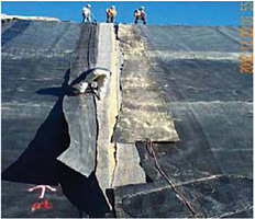
FIGURE 4.2 GCL seam separation at a California landfill. SOURCE: County of Riverside (2004).
GCL and geomembrane at the toe of steep side slopes under these conditions (personal communication, J.P. Giroud, independent consultant, and Jeff Dobrowolski, Geosyntec Consultants, October 2004), which appears to support this shrinkage mechanism. Recent laboratory tests suggest that cyclical wetting and drying can explain a large percentage of the observed shrinkage (Thiel et al., 2006). However, no single mechanism can explain the magnitude and prevalence of panel separations in all cases.
4.3.2
Chemical Compatibility
Chemical compatibility of GCLs, including both cation exchange and pore fluid chemistry effects, has been investigated extensively in both the laboratory and the field. Chemical degradation of the hydraulic conductivity of GCLs is possible when relatively high concentrations of divalent cations such as calcium and magnesium in the natural pore water or soil cause cation exchange with the sodium in the bentonite. For example, in one field investigation of a cover, laboratory tests on exhumed samples and field percolation rates showed that the saturated hydraulic conductivity of the GCL increased by about 100 times due to cation exchange (Benson, 1999, 2001). In a study of the effects of cation concentration and valence, the saturated hydraulic conductivity was correlated to the volumetric swell of GCL bentonite (Jo et al., 2001). Although this investigation was limited to a single cation species, subsequent investigations showed similar correlations with multispecies inorganic chemical solutions as well as with waste leachate (Kolstad et al., 2004; Katsumi and Fukagawa, 2005).
Bentonite quality (e.g., percent sodium smectite, plasticity, cation exchange capacity) and microstructure also influence the chemical compatibility of GCLs. Lee and Shackelford (2005b) and Lee et al. (2005) investigated the effect of bentonite quality on the hydraulic behavior of GCLs permeated with inorganic salt solutions and demonstrated that the higher-quality bentonite GCLs (i.e., higher cation exchange capacity, higher plasticity, higher swell capacity in the presence of water, lower hydraulic conductivity) were more susceptible to chemical attack and increased hydraulic conductivity than the lower-quality bentonite GCLs. Sodium bentonite can be quite susceptible to an increase in hydraulic conductivity when permeated by solutions with a high salt content (Petrov and Rowe, 1997; Lee and Shackelford, 2005b; Lee et al., 2005), especially when the effective stress is low. Under these circumstances it may be more appropriate to use a modified bentonite. However, as noted below, there are many practical situations when the sodium bentonite commonly used in GCLs performs well.
A number of GCL tests have focused on the effects of prehydration (e.g., Katsumi et al., 2004; Lee and Shackelford, 2005a; Thiel and Criley, 2005), confining pressure, cation exchange, and other factors on chemical compatibility. The hydraulic conductivity of a prehydrated and calendared (density has been increased to achieve a uniform thickness and void ratio) GCL appears resistant to degradation from permeation with CaCl2 solutions (Kolstad et al., 2004; Katsumi et al., 2006a). The effects of overburden pressure on the hydraulic conductivity of GCLs permeated by sodium and calcium solutions were found to be significant and depended on the type of chemicals (Katsumi and Fukagawa, 2005). The effect of prehydration is also affected by the applied head pushing the prehydration water into the GCL. However, prehydration by capillary action alone is relatively ineffective in improving chemical compatibility of GCLs in the presence of salts (Vasko et al., 2001). Thiel and Criley (2005) showed that the hydraulic conductivities of GCLs prehydrated and permeated with a variety of waste leachates and water under high effective confining stresses (>500 kPa) were independent of fluid chemistry.
The importance of performing hydraulic conductivity tests long enough to achieve chemical equilibrium between the effluent and influent has been demonstrated for both prehydrated GCLs (Shackelford et al., 2000; Lee and Shackelford, 2005a, 2005b) and nonprehydrated GCLs (Jo et al., 2004, 2005; Katsumi et al., 2006b). Unconservative (low) values of hydraulic conductivity may be measured if the test is terminated before complete chemical equilibrium has been established. For example, in a test for salt compatibility in which the influent contains no sodium cations, true chemical equilibrium is not established until the concentration of sodium in the effluent is zero or below the method detection limit for practical purposes. At this point, cation exchange with the chemical solution has essentially been completed. However, because the method detection limit for sodium is so low (e.g., 0.2 mg/l) and the process of cation exchange in sodium bentonites can be slow (Jo et al., 2005), establishment of true chemical equilibrium can require long test durations (>1 year), which generally increase with decreasing concentration of multivalent cations in the permeant liquid (Jo et al., 2005; Lee and Shackelford, 2005a, 2005b). Thus, measuring the chemical composition of the influent and effluent precisely may be impractical, and meeting method detection limit criteria may not be possible for most applications.
As a result, Jo et al. (2005) recommend that electrical conductivity be used as a measure of chemical composition for the influent and effluent as proposed by Shackelford et al. (1999) and that tests be terminated once the effluent-to-influent electrical conductivity ratio is within 1.0 ± 0.05. This would acknowledge that the long-term hydraulic conductivity may be as much as three times higher than the reported hydraulic conductivity. Alternatively, Jo et al. note that if tests are terminated when the electrical conductivity ratio is within 1.0 ± 0.1 (as per ASTM D 6766), the hydraulic conductivity could be as much as 10 times higher than the reported hydraulic conductivity for conditions similar to those examined by Jo et al. (2005).
The hydraulic conductivity k of nonprehydrated GCLs
permeated with inorganic chemical solutions was correlated with two chemical parameters: (1) the ionic strength of the solution I, which is the sum of the product of the molar concentration and the square of the charge for all ionic species in solution, and (2) the ratio of the molar concentrations of monovalent cations MM to divalent cations MD in the solution, or RMD (= MM/MD0.5; Kolstad, 2000; Kolstad et al., 2004). The RMD is similar to the sodium adsorption ratio commonly used in the soil science literature. The resulting correlation between the k of GCLs and I and RMD of the permeant liquids is shown in Figure 4.3.
Two observations are apparent from the data plotted in Figure 4.3. First, the hydraulic conductivity increases with increasing ionic strength for a given value of RMD and also increases for a given ionic strength as the RMD decreases toward zero. These trends are consistent with expected behavior in the sense that an increase in concentrations and/or charge is expected to result in an increase in hydraulic conductivity (Shackelford, 1994). Second, the hydraulic conductivity of GCLs to chemical solutions with ionic strengths greater than about 0.2 to 0.4 M can be higher than the typical regulatory standard value of 1 × 10⁻⁹ m/s, and much higher in some cases (e.g., for mine waste, k = 1.2 × 10⁻⁵ at I = 0.81 M). Although the relationship shown in Figure 4.3 is relatively new, several independent assessments using different GCLs and different chemical solutions have shown good agreement between measured k values and the predicted k values based on Figure 4.3 (e.g., Lee and Shackelford, 2005a; Shackelford, 2005; Brown and Shackelford, 2007).
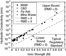
FIGURE 4.3 Correlation among hydraulic conductivity, ionic strength, and the ratio of monovalent-to-divalent cations (RMD) for nonprehydrated GCLs. NOTE: MSW = municipal solid waste; C&D = construction and demolition. SOURCE: Kolstad (2000).
4.3.3
Freeze/Thaw and Shrink/Swell
Freeze/thaw and shrink/swell are medium-term GCL performance concerns associated primarily with GCLs used in covers. The higher confining and overburden pressures applied to bottom-liner systems tend to mitigate these effects. Several studies have investigated resistance of GCLs in the laboratory after as many as 20 freeze/thaw cycles. Little if any change in hydraulic conductivity was measured, suggesting that freeze/thaw is not an important degradation process for GCL performance (Foose et al., 1996; Kraus et al., 1997; Della Porta et al., 2005; Rowe et al., 2006).
In contrast to freeze/thaw cycles, shrink/swell cycles can cause significant degradation of GCLs if (1) the wetting fluid contains multivalent cations, such as calcium or magnesium; (2) the dehydration during drying is severe enough for desiccation cracks to form in the bentonite layer; and (3) the overburden pressure is too low to prevent the formation of desiccation cracks. Under these circumstances, desiccation, combined with the chemical incompatibility effects of cation exchange discussed in the previous section, can cause increases of as much as three to five orders of magnitude in hydraulic conductivity. Desiccation is particularly important when combined with cation exchange because the multivalent cations reduce the ability of the bentonite to swell and heal the desiccation cracks (Lin and Benson, 2000; Sporer and Gartung, 2002a, 2002b). This mechanism of degradation is a particular concern for GCLs in cover systems where the potential for desiccation is greatest because of the combination of large fluctuations in temperature and low overburden pressures. For instance, Melchior (2002) showed the adverse effects of desiccation on five sodium-bentonite GCLs overlain by 0.45 m of cover soil. Both cation exchange and desiccation cracking were observed in exhumed samples (Figure 4.4) and the saturated hydraulic conductivities after exhumation were approximately five orders of magnitude
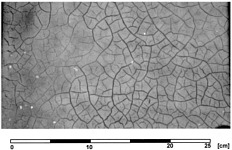
FIGURE 4.4 X-ray image showing desiccation cracks in the bottom layer of a GCL after 5 years in a landfill cover at HamburgGeorgswerder. SOURCE: Melchior (2002).
higher than when the GCLs were installed. Plant-root penetration through the GCL also was observed.
Meer and Benson (2007) exhumed GCL samples from four landfill covers and found similar increases in hydraulic conductivity caused by cation exchange and desiccation cracking. In one case, although the GCL was overlain by a geomembrane, it was still affected by cation exchange, apparently from pore water in the underlying subgrade. Other field investigations confirm that desiccation occurs in GCLs after cation exchange and results in severe degradation of GCLs (Aboveground Tank Update, 1992; James et al., 1997; Benson, 2002; Mackey and Olsta, 2004).
Degradation caused by wet/dry cycles can be prevented by avoiding contact between the GCL and pore fluids containing relatively high concentrations of multivalent cations. A number of laboratory studies have shown that wet/dry cycles do not significantly degrade the performance of sodium-bentonite GCLs, provided that the sodium is not exchanged for divalent cations (e.g., Shan and Daniel, 1991; Boardman and Daniel, 1996; Lin and Benson, 2000). In addition, Mansour (2001) showed that the saturated hydraulic conductivity of a needle-punch-reinforced sodium GCL buried under a moderate thickness (0.66 m) of vegetated cover soil was unchanged after 5 years of exposure to the semiarid climate of Bakersfield, California. The cover soil was rich in sodium, and there was little potential for cation exchange in the GCL. The conclusion drawn from these studies is that desiccation cracks in a sodium-bentonite GCL may heal upon rehydration as long as the pore fluid chemistry in the GCL does not change with wetting and drying cycles and there is sufficient overburden pressure.
In addition, if the extent of drying is not severe, wet/dry cycles may not significantly degrade the performance of sodium-bentonite GCLs. For example, a GCL covered by a thick (1-m) layer of silty sand in a landfill cover subjected to a humid climate exhibited no significant desiccation cracking or other notable defects over a 3-year period despite dry summertime conditions (Blümel et al., 2002). Mineralogical testing on exhumed GCL samples showed that the transition from sodium- to calcium-bentonite due to cation exchange was essentially completed during the 3-year observation period but that ion exchange did not cause any significant increase in permeation (as measured by a lysimeter beneath a GCL) since the dehydration during the drying cycles was not severe. Della Porta et al. (2005) reported that drying temperatures of 105°C degraded GCL performance more than drying temperatures of 60°C.
Other examples of good and bad field performance of GCLs in covers has been discussed by Henken-Mellies et al. (2002), Sporer (2002), Heerten and Maubeuge (1997), Sivakumar Babu et al. (2002), and the potential for cracking and desiccation of GCLs in bottom composite liners due to heat generated by the waste has been discussed by Southen and Rowe (2002, 2004, 2005), and Rowe (2005).
4.3.4
Chemical Transport
Chemical transport parameters, including sorption effects, for GCLs exposed to volatile organic compounds have been reported by Lake and Rowe (2004, 2005a) and Rowe et al. (2004, 2006). Diffusion and sorption factors were such that volatile organic compound migration could be reduced but not controlled to the same level as with a compacted clay liner, unless the GCL was underlain with a suitable thickness of a soil attenuation layer. This effect results primarily because of the relative thinness of GCLs (typically 6 mm) compared to compacted clay liners (typically 0.6 to 0.9 m). Under diffusion-dominated conditions, such as can occur in low-permeability earthen barriers, the steady state diffusive mass flux is estimated by the product of the diffusion coefficient for the chemical species within the porous material (soil) and the concentration gradient, or the difference in concentration across the barrier divided by the barrier thickness. Thus, for the same concentration difference, the concentration gradient for a GCL will be much higher than that for a compacted clay liner. If, in addition, the effective diffusion coefficients for a given chemical species are similar between the GCL and a compacted clay liner (not unexpected since the GCL is usually composed of a natural clay mineral), the diffusive mass flux across the GCL may be expected to be greater than that across the compacted clay liner. In addition, the sorptive capacity of the GCL may be lower than that of the compacted clay liner because the GCL has a lower total mass of sorbent (clay) than the thicker compacted clay liner.
The results of studies aimed at measuring the diffusion coefficients of simple salt ions (e.g., Na+, K+, Cl−) diffusing through GCLs under transient and steady state conditions have been reported by Lake and Rowe (2000), Malusis et al. (2001), and Malusis and Shackelford (2002a). Of particular note is the observation that GCLs can act as semipermeable membranes that restrict the migration of aqueous chemical species (Malusis et al., 2001; Malusis and Shackelford, 2002b). The membrane efficiency coefficient ranges from 0 percent in soils that exhibit no membrane behavior to 100 percent in ideal membranes that restrict the migration of all solutes. In general, the membrane efficiency of natural clay soils that exhibit semipermeable membrane behavior tends to be more prevalent in clay soils with a significant portion of high-swelling clay, such as the sodium bentonite in GCLs (Shackelford et al., 2003). For example, membrane efficiencies ranging from 8 to 69 percent have been reported for a GCL subjected to electrolyte solution with KCL concentrations ranging from 3.9 to 47 mM (Malusis and Shackelford, 2002b). Other factors that affect the existence and extent of semipermeable membrane behavior in clay soils include the stress conditions on the soil and the concentrations and valences of the cations in the pore water (Shackelford et al., 2003). Membrane behavior tends to be most significant for solutions with relatively low concentrations of monovalent cations. However, such dilute solutions can still significantly
exceed regulatory limits (e.g., maximum contaminant levels) for individual contaminant species (e.g., cadmium, zinc, lead; Malusis et al., 2003; Shackelford et al., 2003).
When GCLs exhibit semipermeable membrane behavior, the diffusion of aqueous chemical species (both inorganic and organic) through the GCL will decrease as the membrane efficiency of the GCL increases, so at 100 percent membrane efficiency diffusion of the chemical species is effectively prevented. Thus, GCLs that act as semipermeable membranes perform better as barriers than those that do not. The potential existence of membrane behavior in GCLs adds an order of complexity to the analysis of chemical transport through GCLs that may not be warranted in practical applications, particularly since ignoring the existence of membrane behavior will result in conservative (higher) estimates of contaminant mass flux (Malusis and Shackelford, 2004). However, failure to recognize and account for the existence of membrane behavior also can affect the accuracy of predictions of contaminant mass flux through GCLs, as well as the accuracy of the measurement of transport parameters, which may be important in predicting long-term impacts.
In summary, laboratory and field observations of GCL performance under a variety of conditions suggest that although GCLs alone are not an effective barrier to diffusive transport, they can be effective replacements for low-permeability soil layers as operational barriers to advective transport, provided the integrity of the GCL is maintained during installation and operation. Further, although desiccation may be of concern to GCL integrity, particularly when coupled with cation exchange, it can be mitigated effectively by providing sufficient overburden pressure (e.g., in liner systems). Finally, the adverse effects of chemical incompatibility can be mitigated to some extent or delayed by prewetting the bentonite in the GCL or by permeating the GCL under sufficient overburden pressure.
4.4
DRAINAGE LAYERS
Modern engineered resistive barrier systems generally contain both a low-permeability barrier layer and an overlying high-permeability granular and/or geosynthetic drainage layer. The rate of leakage through a barrier layer increases as the hydraulic head on the barrier layer increases. For example, the rate of leakage through a 1-m-thick compacted clay liner with a hydraulic conductivity of 1 × 10⁻⁹ m/s would increase by about 300 percent if the head on the liner increases from 0.3 to 3 m (i.e., assuming a 1-m-thick clay liner with zero head at the base).
The effectiveness of the barrier system depends not only on the ability of the resistive low-permeable barrier layer to restrict flow but also on the ability of the drainage layer to limit the hydraulic head on the barrier by providing a path for effluent flows of liquid away from the barrier. Inadequate drainage layer capacity is a primary short-term performance concern as leachate flows are generally highest immediately after construction. Medium- and long-term performance concerns include the potential for reduction of capacity from clogging of the drainage layer or overlying filter due to soil infiltration, biological growth, and mineral precipitation. Geosynthetic drainage layers, which are relatively thin, are also susceptible to a reduction in flow capacity caused by penetration of adjacent geosynthetic or soil materials or by compression of the layer itself.
4.4.1
Field Performance
Measurements of field performance of drainage layers in leachate collection or cover systems are much less common than for barrier layers. Most of the available information is indirect, such as indications of leachate mounding or a significant reduction in pumping rates over time in a leachate collection system. The most significant concern with field performance of drainage layers over time is the buildup in head on the underlying barrier layer.
Clogging of leachate collection systems has been observed in landfills with a wide range of collection systems, ranging from French drains (gravel drains at spacing of 50 to 200 m leading to a collection sump) to continuous sand and gravel layers and in systems both with and without geotextile filters (see Table 4.4 and Rowe, 2005). Clogging typically involves a combination of biological clogging, mineral precipitation, and an accumulation into the clog material of fines, as discussed in detail by Rowe (2005). Several field examples of clogging have been reported. For example, field exhumations found that the upper portion of the sand protection layer over a compacted clay liner became clogged within 4 years and thus did not contribute to the hydraulic performance of the collection system (Reades et al., 1989; Barone et al., 1993). Koerner and Koerner (1995) reported clogging of a sand layer where, after 10 years, the hydraulic conductivity dropped three orders of magnitude from 4 × 10⁻⁴ m/s to 2 × 10⁻⁷ m/s and leachate was flowing through the waste rather than through the sand. Koerner et al. (1994) and Koerner and Koerner (1995) reported excessive clogging in two cases where the geotextile was wrapped around either the perforated pipe or the gravel in a drainage trench and some clogging in a third case. A detailed description of a case history where clogging occurred in a leachate collection system is provided in Box 4.4.
Field evidence of leachate collection system performance commonly exhibits deposits of both biofilm and inorganic mineral precipitate on the surface of granular materials. These deposits reduce the drainable porosity and hydraulic conductivity of the drainage material. Clogs of minerals precipitate have been reported to contain over 50 percent calcite, 16 to 21 percent silica, 8 percent iron, and 5 percent manganese (e.g., Brune et al., 1991; Fleming et al., 1999). Calcite (CaCO3) was also the dominant mineral in clog scale obtained from a leachate collection pipe in a Florida landfill that received incinerator ash and municipal solid
TABLE 4.4 Observations from Exhumation of Leachate Collection Systems
waste (Maliva et al., 2000) and in clog scale obtained from a leachate collection pipe in the United Kingdom (Manning, 2000).
Unpublished laboratory studies by Rowe suggest that geonet drainage layers are susceptible to clogging in a manner similar to granular drainage layers. However, much less research has been conducted on these systems. The potential for degradation of flow capacity in geonets—which could arise from clogging, sustained overburden stress, and/or elevated temperatures—is an area that requires more research and collection of field data.
Field evidence for clogging in cover drainage layers is mostly related to slope failures. Clogging by fine particles and/or roots has reduced the drainage capacity of a cover drainage layer and led to slope failure due to increased pore water pressures in several cases (e.g., Koerner and Soong, 1998; Bonaparte et al., 2002; Richardson and Pavlik, 2004). Drainage layers can also become temporarily clogged with ice during a cold spell (Bonaparte et al., 2002) or inadvertently clogged with soil during construction of an adjacent landfill cell (Gilbert, unpublished data).
4.4.2
Geotextile Filters
The use of geotextiles as filters in leachate collection systems has been controversial. Geotextiles will experience some amount of particulate, biological, and chemical clogging, and, as a consequence, a decrease in hydraulic conductivity of up to four to five orders of magnitude could occur. However, based on published data (Koerner et al., 1994; Rowe, 1998), it is unlikely that the hydraulic conductivity of a typical nonwoven needle-punched geotextile would be below 4 × 10⁻⁸ m/s for normal conditions and more likely would be on the order of 1 × 10⁻⁷ m/s or higher. Nonetheless, clogging can be quite problematic if the geotextile is wrapped around leachate collection pipes (Rowe et al., 2004). On the other hand, this level of clogging may not have a significant impact if it is used as part of a blanket drain (McIsaac and Rowe, 2006), especially if measures are taken to control perching of leachate above the geotextile (Rowe et al., 2000).
There is some evidence to suggest that monofilament woven geotextiles selected in accordance with Giroud’s (1996) recommendations are likely to experience less clogging and reduction in hydraulic conductivity with time than the needle-punched nonwoven or slit film geotextiles normally used in practice. Giroud’s recommendations are based on the premise that minimizing clogging of the filter is the objective. This may indeed be the case for some design situations (e.g., wrapping the geotextile around a pipe). However, while excessive clogging is undesirable, the processes that cause clogging provide some beneficial leachate treatment that (1) decreases the potential for clogging at more critical zones (e.g., near collection pipes) and (2) reduces the level of leachate treatment required after removal of leachate from the landfill (Rowe, 2005). Based on the available evidence, it appears that suitably selected geotextiles used as a filter above a coarse gravel leachate collection layer can have a
|
BOX 4.4 Case History on Clogging in a Leachate Collection System This case history illustrates that leachate collection systems can clog, giving rise to both a significant leachate mound and a rapid increase in temperature on the liner. The Keele Valley Landfill, described in Box 4.3, is divided into four quadrants (Rowe, 2005). Stage 1 (northeast portion) was constructed between 1983 and 1985. Stage 2 (northwest portion) was constructed between 1986 and 1988. Construction of Stages 3 (southeast portion) and 4 (southwest portion) was started in 1988 and 1990, respectively, and completed in 1994. The leachate collection system in Stages 1 and 2 consists of a series of French drains (50-mm washed, crushed gravel mounds 0.5 m high and spaced 65 m apart) draining into four main 150-mm-diameter, perforated collection pipes (8-mm-diameter perforations) encapsulated in 40-mm washed, crushed gravel mounds 0.5 m high and 200 m apart. In Stages 3 and 4 the leachate collection system consists of a granular drainage blanket (0.3-m thick, 50-mm washed, crushed gravel) draining into the four main leachate collection pipes. The four primary pipes are 900 to 1,200 m long and run predominantly northwest to southeast across the full length of the landfill and drain to a common holding tank. Field exhumations (Reades et al., 1989; Barone et al., 1993) found that the upper portion of the sand “protection” layer over the liner became clogged within the first 4 years and did not contribute to the hydraulic performance of the collection system. In addition to visual evidence of clogging in the upper portion of the sand layer, the absence of flow in the sand layer was clearly shown in the diffusion profile, which demonstrates that the sand layer was acting as part of the liner in terms of a “diffusion barrier.” A particularly notable observation is that both the inorganic contaminant chloride and several organic contaminants (especially toluene) exhibit diffusion profiles through both the sand and the clay. Such profiles would not be found if there was any significant flow in the sand layer. Exhumation of portions of the continuous gravel drainage blanket in later stages of the landfill (Fleming et al., 1999) indicated a drop of three orders of magnitude in the hydraulic conductivity of relatively uniform 50-mm gravel near the leachate collection pipe after 4 years (although the hydraulic conductivity was still sufficient to transmit leachate without the development of a significant leachate mound). Clogging was observed to be substantially less in areas where a geotextile filter was used between the waste and the gravel than in areas where the waste was in direct contact with the gravel. The main header line leading to the main manhole was found to be partially occluded by solid, biologically induced precipitant, which included some particulate material that had become part of the clog and had formed within the pipe. In the spring of 2001 the main header was so occluded with clog material that a pipe observation camera could not enter the pipe. The liner temperature above the compacted clay liner has been monitored at four locations over a 21-year period (Barone et al., 2000; Rowe, 2005). In Stage 1 the temperature increased slowly and remained low (average 12°C) for the first 6 years and then increased rapidly as the leachate mound grew from 1 to 6.5 m. Subsequently, the temperature stabilized at about 37°C, although the leachate mound continued to increase to about 8.4 m (the leachate mound has subsequently reduced slightly, likely due to installation of the final cover). In Stage 2 the temperature remained relatively constant and low (average 10°C) for the first 5 years and then increased rapidly to 24°C over the next 6 years as the leachate mound grew from about 1 to 5 m. The temperature has continued to increase to 35°C (with no sign of stabilization to date), even though the leachate mound has dropped to about 3 m (due primarily to installation of the final cover). In Stages 3 and 4 the blanket drain leachate collection system continues to function well, although the temperature rose from 15°C in 1998 to 31 to 32°C in 2004. At monitors where the leachate head is less than 0.3 m, 8 to 12 years was required for the temperature on the liner to reach 20°C but only another 3 to 4 years to reach 30°C. The current temperature appears to have stabilized at about 35–40°C. |
beneficial effect of extending the service life of the leachate collection system (Fleming et al., 1999; Rowe, 2005; McIsaac and Rowe, 2006).
4.4.3
Mechanisms of Biological and Chemical Clogging
Field evidence suggests that biological and chemical clogging is a significant concern for leachate collection systems. Biological clogging is initiated by microorganisms that are suspended in leachate attaching to and colonizing the porous media surfaces as a biofilm (Rowe et al., 2004). The development of the biofilm is a function of the growth rate of the microorganisms, substrate concentration, attachment of microorganisms from the leachate onto the surface of the porous medium, and the detachment of microorganisms from the biofilm into the passing leachate. For MSW landfills, the precipitation of Ca2+ as CaCO3 is directly correlated with the biodegradation of organic acids.
Available information (Rowe, 2005) indicates that development of a biofilm occurs relatively quickly and then, with time, changes from a soft slime to a slime with hard particles (sand-size solid material in a soft matrix), to a solid porous concretion of a coral-like “biorock” structure (VanGulck and Rowe, 2004). During the early phases of clog development, the biofilm is relatively easy to clean from leachate collection pipes (e.g., by pressure jetting). However, once the biofilm becomes sufficiently established to cause significant precipitation of CaCO3, the inorganic film becomes firmly attached to the adjacent media (e.g., perforation) and the
inside of pipes (Fleming et al., 1999) and is very difficult to remove. This behavior implies that leachate collection pipes in landfills need to be regularly cleaned to remove the soft biofilm in its early stages of development. The rate of clog development has been found to accelerate with time, and hence the rate of inspection/cleaning required in pipes may need to increase with time as biofilms develop and as the concentration of volatile fatty acids in the leachate (or chemical oxygen demand) increases.
Due to the level of “treatment” that occurs in a leachate collection system before the leachate reaches the collection point, end-of-pipe analyses of volatile fatty acids and Ca2+ concentrations in the leachate only indicate the condition at the collection point and provide little evidence regarding the nature of the leachate that enters the system (Rowe, 2005).
Use of carbonate gravel in the drainage layer has been suggested as unsuitable because it could dissolve and contribute to subsequent calcite crystallization on alkaline biofilms covering drainage gravel (e.g., Brune et al., 1991). However, a considerable body of evidence now suggests that calcium carbonate is generally supersaturated in landfill leachate very early in the life of the landfill such that it is unlikely dissolution would occur under these conditions (e.g., Rittmann et al., 1996; Owen and Manning, 1997; Jefferis and Bath, 1999; Manning and Robinson, 1999; Bennett et al., 2000). The evidence points to Ca2+ leaching out of the waste and being transported to the point of deposition by the leachate, while the CO32− predominantly forms from the mineralization of organic carbon by microorganisms (Brune et al., 1991; Owen and Manning, 1997; Bennett et al., 2000).
An understanding of basic clogging mechanisms from laboratory and field studies led to the development of a simple method for estimating the rate of clogging of different collection system designs that uses calcium as a surrogate for other clog materials (e.g., magnesium, iron) that may deposit within the drainage layer (Rowe and Fleming, 1998; Rowe et al., 2004). Although this methodology is dependent on porosity, no distinction is made for different particle sizes and specific surface areas; thus, it should be used with caution and only for relatively uniformly graded granular material (Rowe, 2005).
New understanding of clogging has allowed the development of a numerical model, BioClog, to simulate clogging in both column experiments (Cooke et al., 2005) and two-dimensional flow systems. Reactive chemical transport is modeled with consideration of biological growth, mineral precipitation, and attachment and detachment of suspended solids. The porous medium is represented as a fixed-film reactor, and changes in porosity resulting from the development of biofilm and inorganic films (e.g., calcium carbonate) can be directly calculated based on a geometric model. The corresponding changes in hydraulic conductivity are then deduced based on empirical relationships derived from laboratory tests. For two-dimensional systems a flow model is coupled with the transport model.
The BioClog model is sufficiently mature to be used to predict clogging in landfill drainage systems. However, because of the highly coupled and complex nature of the model, it is unlikely to be used in routine engineering practice. Nonetheless, models such as this provide insight that can both improve interpretations of laboratory test results and field monitoring measurements and aid in evaluating the likely difference in the performance of different types of leachate collection systems.
4.4.4
Summary
In summary, drainage layers are important barrier components for reducing leachate head on liners and covers, thereby reducing advective transport and enhancing slope stability. However, field measurements of performance of drainage layers in leachate collection or cover systems are much less common than for barrier layers. The available evidence indicates that drainage layers can be susceptible to clogging from a variety of mechanisms, including chemical and biological precipitation and infiltration of fine particles. More research is needed on the field performance of drainage layers.
4.5
EVAPOTRANSPIRATIVE BARRIERS
Performance concerns for evapotranspirative barriers include the following:
-
Short term: inadequate material, inadequate thickness, and inability to establish vegetation, which lead to excessive infiltration.
-
Medium and long term: inadequate storage capacity for infiltration, inability to sustain vegetation, and the development of cracks and other secondary permeability features, which lead to excessive infiltration; erosion and invasion of inappropriate vegetative species, which lead to intrusion and/or exposure of the waste.
Evapotranspirative barriers have a similar capability as other vegetative soil layers to control gas emissions and resist intrusion and erosion. Pan lysimeters are the primary method used to evaluate the infiltration performance of evapotranspirative covers. Lysimeters provide an accurate representation of this performance, subject to the boundary conditions imposed by the lysimeter installation, and thus can provide valuable information on their effectiveness as a capacitive barrier to infiltration. Two case histories of lysimeter measurements illustrating the effectiveness of evapotranspirative barriers in controlling infiltration are given in Box 4.5. Lysimeter test pads are being used to monitor the performance of these barriers as elements of a waste containment system, although lysimeter measurements have shortcomings when used in this way (see Section 3.2.3).
Few conclusive data are available on the performance of evapotranspirative covers in temperate climates. However, available field evidence suggests that these covers can be an
effective alternative to compacted clay or composite covers in arid and semiarid climates where evapotranspiration is an important component of the water balance and in wetter climates where it is not essential to minimize infiltration. Since most test sites being monitored were established in the late 1990s, it is difficult to effectively predict the performance of evapotranspirative barriers over extended periods of time. However, natural analogs can be used to estimate the long-term performance of cover systems (Caldwell and Reith, 1993). For instance, natural landscapes that have remained stable for hundreds or thousands of years exist in arid and semiarid regions, such as a desert varnish crust in the southwestern United States, and may provide analogs for erosion control. Geological and hydrological data from these established landscapes suggest that long-term infiltration to the subsurface is negligible. Studies of natural analog sites could provide valuable insights on the long-term efficacy of evapotranspirative systems in arid and semiarid climates as well as the long-term performance of other types of cover systems in other climate regimes.
4.6
VERTICAL BARRIERS
Vertical waste containment barriers (cutoff walls) have been constructed using soil-bentonite, cement-bentonite, soil-cement-bentonite, Portland cement concrete (PCC), sheet piling, and geomembrane panels. In addition, gravel-filled interceptor and extraction trenches can be effective vertical barriers by cutting off the continuity of lateral advective and diffusive flow and removal of contaminants from the system. These types of barriers are commonly incorporated as components of site remediation and cleanup systems.
Slurry wall construction methods have been used most extensively for vertical barrier construction. Deep soil mixing and jet grouting methods have also been used, although deep soil mixing is limited by the ability to achieve sufficiently low saturated hydraulic conductivity and the use of jet grouting is limited by concerns about continuity of the barrier. As few data specific to vertical barrier walls are available for evaluation of their effectiveness as waste containment barriers, unambiguous conclusions concerning their performance cannot be reached. Some relevant considerations, findings, and data that provide preliminary indications of how well they may meet their objectives are summarized below.
Short-term performance concerns for soil-bentonite and cement-bentonite vertical cutoff walls include defective material and “windows” caused by caving or trapped low-quality material at joints between panels. Extensive experience using these types of walls for groundwater control in excavations, however, indicates that if properly designed and constructed, they provide excellent barriers against groundwater flow under heads ordinarily considerably higher than those likely to be encountered in waste containment applications. Medium- and long-term performance concerns include property changes due to chemical incompatibility and to desiccation above the water table for soil-bentonite walls, cracking for soil-bentonite and cement-bentonite walls, and chemically-induced deterioration (e.g., sulfate attack) for cement-bentonite walls. Failure of vertical cutoff walls can be attributed to two primary mechanisms: (1) defects in the constructed wall, including entrapped sediment, improperly mixed backfill, inadequate excavation of the key, and formation spalling (Evans, 1991); and (2) changes in the material properties after the wall has been constructed. Inadequate excavation for keying the vertical wall into the underlying impervious layer is among the most common problems when using cement-bentonite walls. Property changes within cutoff walls can be caused by the same mechanisms that affect compacted clay liners: desiccation, freeze/thaw, chemical incompatibility, and excessive deformations.
Short-term concerns for PCC cutoff walls are similar to those for cement-bentonite walls, especially if they are constructed using tremie placement methods in slurry trenches. Formed Portland cement concrete walls are susceptible to a variety of short-term cracking mechanisms. Longer-term concerns for PCC walls include cracking caused by several possible mechanisms and corrosion of reinforcement.
Driven sheet pile walls can be an attractive alternative for construction of vertical waste containment barriers because of their relative ease of installation and the imperviousness of the sheet piles themselves. Sheet pile walls include both steel sheet piles and polymer sheet piles. Leakage through the interlocks and the possibility that some piles may be driven out of their interlocks during installation are major limitations on the short-term performance of sheet pile walls. Other factors that potentially affect the performance of sheet pile walls include the ability to effectively key sheet piles into low-permeability soils and rocks, and the potential limitation on the depth of penetration. Corrosion may limit the long-term effectiveness of steel sheet piles.
Geomembrane panels may also be used as vertical barriers. As is the case for steel sheet pile walls, one of the most critical factors that affect short-term performance of geomembrane panels is the integrity of the interlocks that connect the geomembrane panels in the barrier. Medium-and long-term durability concerns for vertical geomembrane panels are similar to those for geomembrane liners.
4.6.1
Soil-Bentonite Walls
Measurement of the hydraulic conductivity of soil-bentonite cutoff walls can be performed in the laboratory or in situ. Laboratory tests can be performed on samples recovered using thin-walled tubes from the wall after construction. The tests can be conducted in consolidometer permeameters or flexible-wall permeameters, although this type of laboratory testing may be difficult because the soft nature of the materials makes sample recovery and extrusion of the sample difficult (Britton et al., 2004). Laboratory tests on remolded specimens created using bulk samples of wall
backfill recovered during wall construction are likely to be useful only if the testing procedures provide a sample state and confinement conditions that are representative of the material in situ. In situ hydraulic conductivity tests can be conducted within the wall following construction. In situ tests include slug tests, piezocone soundings with pore pressure dissipation measurements, and large-scale pumping and injection (Britton et al., 2004).
A comparison of laboratory and field methods to evaluate the hydraulic conductivity of soil-bentonite backfill in pilot-scale cutoff walls showed that laboratory tests performed on remolded and thin-walled tube samples, respectively, yielded
|
BOX 4.5 Case Histories on Performance Assessments for Evapotranspirative Barriers These case histories illustrate the field performance of evapotranspirative barriers. Evapotranspirative barriers were constructed and monitored as part of the Environmental Protection Agency’s Alternative Cover Assessment Program (Albright et al., 2004). All test sections were installed withina 10- to 20-m instrumented pan-type lysimeter for direct measurement of surface runoff, soil-water storage, and percolation. The base and sidewalls of each lysimeter consisted of polyethylene geomembrane. A geocomposite drainage layer was placed in the base of the lysimeter to route water to a collection and measurement system. Diversion berms were constructed around the perimeter of each test section to prevent run-on and to collect runoff for measurement. The water content of cover soils was measured with time domain reflectometry probes placed at varying depths in the cover profile. Thermal dissipation sensors were used to measure soil-water matric potential. A description of installation methods for the lysimeters is given in Benson et al. (1999). Surface runoff (SRO), percolation (Pr), and precipitation (P) were all measured directly, whereas soil-water storage (SWS) was calculated by integrating volumetric water content measurements over the volume of the lysimeter. Evapotranspiration (ET) was calculated according to the water balance equation ET = P − SRO − Pr − Lo − ∆SWS, where Lo is lateral drainage. The test sections described in this case history did not contain internal drainage layers such that lateral drainage was assumed as nil (Lo = 0). Boardman, Oregon. The alternative cover is located at the Finley Buttes Regional Landfill in Boardman, Oregon. Boardman receives an average annual precipitation of 225 mm with a precipitation/potential evapotranspiration (P/PET) ratio of 0.23, which corresponds to a semiarid climate (Albright et al., 2004). The weather in Boardman is warm and dry in the summer and cool and wet in the winter, with over two-thirds of the annual precipitation occurring between November and March. The alternative cover is a monolithic cover consisting of a storage layer over an interim cover (Figure 4.5). Construction of the test section was completed in November 2000, and data collection began in December 2000. The test section was seeded in December 2000 with a mixture of indigenous grasses, including crested wheatgrass, alfalfa, and clover (Bolen et al., 2001). The surrounding native vegetation is described as shrub-steppe (i.e., sagebrush and grasses). Polson, Montana. The alternative cover at Polson, Montana, is located at the Lake County Landfill. Polson has an average annual precipitation of 380 mm and a P/PET ratio of 0.58, which corresponds to a subhumid climate (Albright et al., 2004). The alternative cover is a capillary barrier cover consisting of topsoil overlying a sandy silt storage layer overlying a capillary break comprised of coarse-grained silty sand, which in turn overliesa sandy gravel layer that serves as an interim cover and gas vent (Figure 4.5; Roesler et al., 2002). Construction of the test sections was completed in October 1999, and data collection began in November 1999. The test sections were seeded in March 2000 with a combination of native and introduced vegetation, including bluegrass, wheatgrass, alfalfa, and prickly rose shrubs (Bolen et al., 2001). 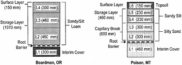 FIGURE 4.5 Schematic cross sections of alternative earthen final covers discussed in this case history. SOURCE: Ogorzalek (2005). |
|
Water Balance Measurements. The measured water balances at both sites are shown in Figure 4.6. Although several factors differ, including the periods of record (3 years for Boardman and 4 years for Polson), the type of alternative cover, and the amount of precipitation, some consistent trends can be observed. First, the surface runoff at both sites is relatively insignificant. Second, the vast majority of the precipitation at each site is taken up by evapotranspiration, emphasizing the importance of vegetation in evapotranspirative barriers. Finally, both alternative covers apparently performed exceptionally well over the period of record, with no measured percolation occurring at Boardman and only 0.8 mm of cumulative percolation occurring at Polson. 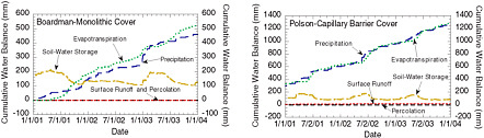 FIGURE 4.6 Measured water balances for alternative covers at Polson, MT, and Boardman, OR. SOURCE: Modified from Shackelford (2005); data from Bohnhoff (2005) and Ogorzalek (2005). |
the lowest values for hydraulic conductivity, followed by the in situ methods (piezocone and piezometer; Britton et al., 2004). Large-scale pumping/injection tests performed using wells located in the aquifer contained by the cutoff wall gave higher values than either the laboratory or field measurements, suggesting that isolated defects within the wall exert a significant influence on barrier effectiveness. Testing of soil-bentonite walls using slug tests (instantaneous change in water level, followed by monitoring until the water level returns to static conditions) with a push-in piezometer tip has been recommended as an efficient method for evaluating soil-bentonite wall hydraulic conductivity that limits disturbance while still testing a relatively large volume of material (Britton et al., 2005a; Choi and Daniel, 2006a, 2006b). Nevertheless, such tests do not ensure detection of isolated defects that could dominate the overall effectiveness of the barrier, as suggested by the large-scale pumping tests.
The possible effects of chemical incompatibility, described above for earthen barriers and geosynthetic clay liners, may also apply to soil-bentonite cutoff walls. However, factors such as the type of soil used to create the soil-bentonite backfill and stress conditions within the wall may also be important in the case of soil-bentonite walls because of the lack of significant waste overburden.
4.6.2
Cement-Bentonite Walls
Cement-bentonite is sometimes used as an alternative to soil-bentonite for construction of subsurface vertical barriers. Cement-bentonite is also sometimes used as a flowable low-permeability backfill around pipes carrying leachate or other contaminated liquids and in trenches. Cement-bentonite barriers are much more popular in Europe than in the United States, where soil-bentonite barriers predominate because of cost considerations and concerns about the hydraulic conductivity of cement-bentonite mixtures. The technical basis for resistance to the use of cement-bentonite as a barrier material in the United States is the difficulty of achieving a sufficiently low initial hydraulic conductivity. Cement-bentonite mixes usually have an initial hydraulic conductivity on the order of 10−8 and 10−9 m/s, whereas a value no greater than 10−9 m/s is typically employed as the standard for vertical barriers. However, extensive research and experience in the United Kingdom and Europe show that a hydraulic conductivity of <10−9 m/s can be achieved by supplementing the cement-bentonite mixture with ground granulated blast furnace slag (Jefferis et al., 1999). Although the initial hydraulic conductivity of a cement-bentonite-slag mixture may be >10−9 m/s upon initial emplacement, laboratory testing of both archived samples and cores recovered from walls shows that the hydraulic conductivity subsequently decreases and routinely achieves a value of <10−9 m/s within a year (Jefferis, 1995), as illustrated in Figure 4.7. In the United States, fly ash is often added to cement-bentonite mixes to lower the initial hydraulic conductivity below 10−9 m/s. Blast furnace slag has also been used in some U.S. installations (Opdyke and Evans, 2005) to decrease the permeability of cement-bentonite mixes.
Limited information on chemical compatibility suggests that both the short-term resistance and the medium-term
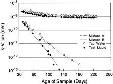
FIGURE 4.7 Hydraulic conductivity of soil-bentonite (mixture A) and cement-bentonite (mixture B) mixtures from Jefferis (1995). SOURCE: Rumer and Mitchell (1995).
resistance of cement-bentonite mixtures to degradation by organic solvents are good. Compatibility tests conducted by Manassero et al. (1995) on cement-bentonite mixtures with pure ethanol indicate that the ethanol did not have a significant effect on the hydraulic conductivity of the test specimens because the intrinsic permeability of the specimens with ethanol and water were similar. Similarly, relatively low effects were observed on the hydraulic conductivity of cement-bentonite mixtures tested in the laboratory with leachate from a phosphogypsum (calcium sulfate) landfill (pH = 2.0) when compared to permeation with water (Fratalocchi et al., 2005). Diffusion coefficients similar to those for compacted clay soils were reported for cement-bentonite mixes (Manassero et al., 1995).
Construction quality assurance procedures for cement-bentonite walls are similar to those for soil-bentonite vertical barriers. Besides monitoring the placement of the cement-bentonite in the slurry-filled trench used for wall construction, cylinders of the cement-bentonite mix are periodically recovered, cured for 7 to 28 days, and then tested for hydraulic conductivity. Recommendations for the design of cement-bentonite walls and CQA procedures are provided in Manassero et al. (1995). Cement-bentonite vertical barriers have been employed for environmental remediation in the United Kingdom since the late 1960s, and as of 1994 no failures of these types of barrier walls had been reported (Rumer and Mitchell, 1995).
4.6.3
Portland Cement Concrete Barriers
The intact (uncracked) hydraulic conductivity of PCC depends primarily on the water/cement ratio, the degree of hydration, and supplemental cementitious materials or mineral admixtures (e.g., fly ash, silica fume, blast furnace slag) used in the concrete mix. The bulk hydraulic conductivity depends on the intact hydraulic conductivity and microstructural features, including cracks in the concrete, concrete diffusivity, the internal pore system of the concrete, and the character of the cement paste-aggregate transition zone. High-strength concrete generally has a relatively low intact hydraulic conductivity, suggesting that it can provide a high degree of effectiveness as a barrier to advective flow. However, its brittleness and susceptibility to plastic shrinkage and restrained cracking create secondary features that reduce the bulk hydraulic conductivity. Hydraulic conductivity on the order of 1 × 10⁻¹⁰ cm/s is readily achievable in uncracked PCC with a low to moderate water-cement ratio (Hearn et al., 1994). The inclusion of supplemental material, such as blast furnace slag, silica fume, and fly ash, in addition to or as a partial replacement for Portland cement, further decreases the intact hydraulic conductivity of concrete (Thomas et al., 1999; IAEA, 2001). However, relatively few through-going cracks can increase the bulk hydraulic conductivity by several orders of magnitude compared to the intact value (Snyder, 2000).
There are two main approaches to mitigating the impact of cracking on the performance of concrete barriers: (1) accept that cracking will occur and engineer a containment system that meets performance requirements even after the concrete cracks or (2) develop measures to minimize cracking. Cracking mechanisms in PCC include plastic shrinkage and restrained shrinkage cracks that develop during curing, settlement cracking that occurs during placement, flexural cracking caused by deformation after placement, thermal cracking, drying shrinkage cracking, cracking caused by corrosion and subsequent expansion of steel reinforcement, and autogeneous shrinkage cracks caused by chemical shrinkage stresses that develop after curing (ACI, 2006). The use of coarser cement paste with longer curing times may mitigate cracking associated with curing. Cracks that develop as a result of placement conditions (e.g., plastic shrinkage, settlement) can be minimized by using good construction practices, but some cracking of this sort may be inevitable. Similarly, some, but not all, thermal cracking and flexural cracking can be mitigated through reinforcement. Finally, cracking may be mitigated by incorporating supplemental water into the concrete mixture. Approaches that attempt to employ this mechanism include the use of lightweight aggregates saturated with water and the inclusion of absorbent polymers saturated with water into the concrete mixture (Bentz and Jensen, 2004). However, these approaches are still experimental, and little information is available on how they affect long-term performance.
Cracking caused by ion transport is a problem for long-term performance of PCC barriers. Both sulfate and chloride ion diffusion can induce degradation and cracking in concrete. While the use of ASTM Type V cement can slow the onset and progression of sulfate degradation, the ability of sulfate-resistant concrete to prevent cracking from sulfate
ion diffusion for hundreds to thousands of years is unknown (Ferraris et al., 1997). Chloride diffusion is perhaps an even more serious problem for steel-reinforced concrete. Chloride ions that move through concrete by diffusion and advection can induce corrosion of metallic reinforcement and generate expansion products. The permeability of concrete to chloride may be inhibited by the use of supplemental cementitious materials and other admixtures. Techniques for measuring the chloride permeability of concrete include ponding tests and rapid chloride permeability measurement (Mobasher and Mitchell, 1988).
The corrosion of reinforcement and the associated expansion products can lead to both expansion-induced stresses and loss of tensile capacity of the reinforcement and thus make the concrete more susceptible to cracking. Nonmetallic reinforcing elements (e.g., fiber, fiber-reinforced plastic, or polymer grid reinforcement) may be used to mitigate problems with corrosion of steel reinforcement. However, experience with this type of reinforcement for long-term durability is limited. Other mitigation measures include the use of ASTM Type V low-alumina cement to minimize sulfate-induced degradation and/or blended cements (e.g., cements with supplemental cementitious materials and mineral admixtures to reduce concrete permeability). Extensive laboratory testing indicates that supplemental cementitious admixtures combined with relatively low water-cement ratios reduce both concrete permeability and chloride diffusivity (IAEA, 2001). However, in some cases diffusion may be beneficial. For example, fine cracks may close through autogeneous healing caused by transport of sulfate and other minerals with low gradients.
The susceptibility of PCC barriers to cracking is demonstrated by the difficulty in controlling vapor transmission through building slabs (EPA, 2002a). Indoor air pollution caused by transmission of volatile organic compounds through concrete foundation slabs is a persistent problem at sites underlain by contaminated groundwater plumes. When buildings are constructed on top of or within MSW landfills that generate methane, building codes often require that a geomembrane be placed beneath the slab to control vapor intrusion. Although incorporation of supplemental water or beneficial material (e.g., blast furnace slag) into the concrete mixture, use of nonmetallic reinforcement, and more rigorous CQA procedures may limit cracking in concrete slabs used as barriers for waste containment, some cracking appears to be inevitable with current technology and must be accommodated in the design of the barrier.
Construction quality assurance of PCC barriers generally consists of strength testing of cylinders created at the time the concrete mix is poured. Although these tests can detect deficiencies in the concrete mix, they are not really suitable for detecting cracks that develop in the concrete during or after curing. Furthermore, statistical methods used to evaluate the test results are generally targeted at evaluating the overall strength of the concrete mass, not its hydraulic conductivity or susceptibility to cracking. However, there appears to be a good correlation between the strength and cracking resistance of PCC in the short term. Several nondestructive testing methods have been proposed as a means of PCC quality assurance. Seismic velocity testing is now used routinely to evaluate the integrity of cast-in-drilled-hole deep foundations. However, this method is aimed at identifying relatively large zones of defective concrete rather than the micro-cracking of concrete that is likely to impair the long-term integrity of a PCC barrier. Air permeability measurements (Kollek, 1989; Torrent, 1992; Lydon, 1993; Ismail et al., 2006) may provide a more direct measure of microstructural cracking in concrete.
4.6.4
Sheet Pile Barrier Walls
The primary short-term problem with the performance of sheet pile barriers is inability to achieve an adequate seal at the interlock between adjacent sheet piles. Several different sealing systems have been developed, including the use of hydrophilic material to line the interlocks and the provision of tubes and channels to facilitate grouting of the interlocks after driving is complete. The so-called Waterloo Barrier, a patented sheet pile system specially designed for environmental containment system applications that employs a sealable joint, is one of the more common systems.1
The results of two studies to evaluate flow through sheet pile walls used as vertical barriers were reported by McMahon (1995). In one study, bentonite slurry and an organic polymer were used to seal the interlocks between the panels of Waterloo Barrier sheet piles. With the bentonite slurry as an interlock sealant, a bulk hydraulic conductivity of 6 × 10⁻¹¹ m/s was reported for the wall system, whereas the bulk hydraulic conductivity for the Waterloo sheet pile wall using the organic polymer sealant was reported to be less than 1 × 10⁻¹¹ m/s. In the other study, a sheet pile barrier using Arbed sheet piles (European sheet piles with a different interlock system than sheet piles manufactured in the United States) was driven through a silty sand deposit into an underlying clay deposit and a field pumping test was performed using a pumped well and four observation wells. In this case, no interlock sealant was used and the measured bulk hydraulic conductivity of the wall system was 7 × 10⁻⁹ m/s.
Concerns about medium- and long-term performance of sheet pile vertical barriers include deterioration of the joint sealing material due to chemical incompatibility, material degradation, sustained hydraulic gradients, the impact of ground displacement and vibrations on the integrity of joint seals, corrosion of steel sheet piles, and stress cracking of polymer sheet piles. Few data on medium- and long-term field performance exist for sheet pile barriers. However, sheet pile containment systems are frequently used only for short-term containment, after which they can be removed
and reused, which is beneficial because of their greater cost compared to soil-bentonite vertical barrier containment systems.
4.6.5
Geomembranes as Vertical Barriers
Geomembranes have been used as vertical barriers either alone or in conjunction with other relatively low permeability materials, such as in composite cutoff walls (see Chapter 2) since about 1985. Koerner and Guglielmetti (1995) describe several case studies involving the use of geomembranes as vertical barriers, either alone or in conjunction with other materials (e.g., cement-bentonite slurry) or other technologies (e.g., jet grouting) for a variety of purposes, including as seepage cutoffs in earth dams and for containment of hazardous, petroleum, municipal, and contaminated drilling wastes. However, the case studies focused on the use and installation of the geomembranes, not their field performance. Similar to vertical sheet pile barriers, the primary short-term performance concern associated with geomembrane barriers is the integrity of the joints between panels. Several joint sealing systems have been developed, but little performance data on these systems is available. The installation of a vertical geomembrane barrier within a soil-bentonite wall is one approach that has been used to alleviate concerns over joint integrity. Long-term performance concerns with vertical geomembrane barriers are similar to long-term performance concerns associated with geomembrane liners.
4.6.6
In Situ Grouting for Vertical Barriers
In situ grouting is an established technology that has been used extensively in construction applications for two primary purposes: (1) to shut off seepage or create a barrier against groundwater flow and (2) to increase strength and decrease compressibility of soil formations for the purposes of increasing bearing capacity and stability and decreasing settlement and ground movement (Koerner, 1984; Karol, 2003). However, the use of in situ grouting for waste containment applications is relatively new. The primary short-term concern with the use of grouted barriers for environmental protection is the lack of continuity in the barrier. This concern, as well as the lack of a reliable method for evaluating the continuity of a grouted barrier, are perhaps the most significant reasons that grouting is not used more extensively for containment applications. The primary long-term concern with the performance of grouted barriers is the potential for degradation of the grout due to chemical incompatibility. While extensive laboratory tests have been performed for a wide range of chemical grouts, only a few chemical grouts have been tested in field studies, and those field studies have emphasized evaluation of placement methods, not barrier performance (Whang, 1995). As a result, data on the long-term field performance of vertical waste containment barriers created by in situ grouting are virtually nonexistent.
4.6.7
Gravel-Filled Trenches as Vertical Containment Barriers
Vertical trenches, typically up to a meter wide and filled with gravel, can cut off the lateral advective and diffusive flow of contaminants, while also facilitating removal and treatment or disposal of the contaminants. This system provides both an effective waste containment barrier and source reduction. A fluid collection and removal system at the bottom of the trench is an essential component of such a barrier. In hard ground it may be possible to excavate an open trench and then dump in gravel. In soft ground, lateral support is needed prior to replacement of the native material by the gravel backfill. This can be done by using the slurry trench method and a biodegradable drilling mud to hold the trench open and then backfilling with gravel. A case history illustrating the effective use of a gravel-filled trench at a Superfund site is described in the next chapter. The primary performance concerns with gravel-filled trenches are long-term clogging of the collection system and mechanical breakdown of the extraction system. Clogging can occur due to accumulation of sediment or, in some cases, biological growth and/or mineral precipitation. Because gravel-filled extraction trenches are active systems, they require constant maintenance and monitoring, which increase costs but facilitate identification and remediation of clogging and mechanical breakdown.
4.6.8
Contaminant Transport Through Vertical Barriers
The possible scenarios for chemical transport through vertical cutoff walls are depicted in Figure 4.8. Pure diffusion (a) is an ideal case; diffusion with advection (case b) occurs when unmitigated buildup of contaminated water retained by the wall is allowed to occur; and diffusion against advection (case c) occurs when the contaminated water inside the containment area is drawn down (e.g., by pumping or drainage) to induce inward flow of water.
Recently, the effect of variability in aquifer hydraulic conductivity on chemical transport through soil-bentonite vertical barriers has been evaluated (Filz et al., 2003; Britton et al., 2005b). In the Britton et al. study, the impact of log-normal variation in hydraulic conductivity values on both steady state and transient contaminant flux through a cutoff wall with idealized initial and boundary conditions was investigated. The results showed that contaminant flux through cutoff walls increases as the variability in hydraulic conductivity increases, all other variables being constant. The effect of variability was found to be most pronounced for the case of diffusion against advection (Figure 4.8c) because the increase in inward advective flux in areas where the seepage velocity is higher than average is more than offset by the increase in outward diffusive flux in areas where the seepage velocity is lower than average.
As with GCLs, the existence of membrane behavior in soil-bentonite cutoff walls has been postulated on the basis of
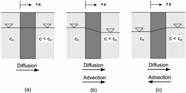
FIGURE 4.8 Chemical transport scenarios for vertical barriers: (a) pure diffusion, (b) diffusion with advection, and (c) diffusion against advection. SOURCE: Sleep et al. (2006). Copyright 2006 by Taylor and Francis Group LLC, Books. Reproduced with permission of Taylor and Francis Group LLC Books via Copyright Clearance Center.
laboratory tests performed on model soil-bentonite backfills consistent with those expected in field-constructed walls (Yeo et al., 2005). More recently, laboratory tests performed on field-recovered backfill materials have confirmed the existence of membrane behavior, but the measured membrane efficiencies were lower than those previously reported for the model soil-bentonite backfills (Henning et al., 2006). The difference was attributed primarily to the lesser amount of fine-grained soils in the field-constructed backfills.
Advection and diffusion are the primary contaminant transport mechanisms through concrete barriers, and sorption also plays an important role. Advective and diffusive transport of ions (e.g., chloride, sulfate) can also have a major impact on the properties of concrete. The resistance of a concrete barrier to advective flow depends on both the intact hydraulic conductivity of the barrier and the presence of through-going cracks that can serve as conduits for the advective flow of liquids and gas. Cracks also affect the rate of diffusive transport through the barrier, even if they are not through-going, as they allow fluids containing the diffusing ions to penetrate the barrier through advective flow, shortening the diffusion pathway and increasing the rate at which the adsorptive capacity of the barrier is expended. Diffusion of ions, particularly chloride and sulfate ions, can also lead to material degradation and enhanced cracking, although at low concentrations sulfate diffusion can help seal cracks. Sorption affects both the time required for radionuclides to break through and the rate at which various degradation mechanisms proceed. These include, notably, corrosion of steel reinforcement, which is a significant contributor to concrete cracking. Hence, the coupling between advective and diffusive flow and interaction between the concrete, concrete reinforcement, and transported ions is an important consideration in concrete barrier performance.
4.6.9
Conclusions
Although few monitoring data on field-installed vertical barrier walls used for environmental protection exist, available evidence suggests that the primary short-term factor affecting vertical cutoff wall performance is poor construction. Chemical incompatibility and corrosion and/or material degradation may be important medium- and long-term concerns for almost all types of vertical barriers.
Only a few high-permeability defects can have a significant adverse impact on the performance of a barrier (Benson and Dwyer, 2006), and soil-bentonite, soil-cement, and tremie concrete walls are particularly susceptible to construction defects. Poor joint seals in sheet pile and geomembrane panel barriers and lack of continuity in grouted barriers can have a similar effect on vertical barrier effectiveness.
Despite the existence of several laboratory and field methods to measure the hydraulic conductivity of soil-bentonite and cement-bentonite walls, none are free of complicating factors that can compromise the reliability of the results (Benson and Dwyer, 2006). These factors include the extensive lengths of cutoff walls and corresponding large volumes of the subsurface contained in the walls, the potential for leakage from the underlying floor (e.g., aquitards into which the wall is keyed) or from the overlying cap, and the inability to distinguish the volume of water passing through the wall during a pump test from that due to drainage of aquifer materials. In addition, most, if not all, of the studies that have been performed to evaluate the potential for chemical
incompatibility of vertical barriers were conducted over time frames that are too short to provide a realistic assessment of the long-term effects that contaminated groundwater can cause in cutoff wall materials (Benson and Dwyer, 2006). Finally, there is virtually no available field evidence or data on the performance of vertical barriers with respect to chemical transport. Because of problems such as these, determination of the effectiveness of vertical barriers in assuring adequate long-term performance of the overall containment system is difficult and requires more study.
4.7
ASPHALT CONCRETE BARRIERS
The primary performance concerns for asphalt cement concrete (ACC) barriers are cracking and degradation. Asphalt concrete barriers are susceptible to similar cracking concerns as PCC walls, although their greater ductility may reduce the cracking potential caused by ground deformations. On the other hand, asphalt is more susceptible to chemical attack by solvent-bearing wastes.
Asphalt cement concrete can have a relatively low intact hydraulic conductivity. By limiting the air voids ratio and increasing the asphalt cement or binder content, the intact hydraulic conductivity of ACC can be as low as 1 × 10⁻⁸ cm/s (Asphalt Institute, 1976). ACC can be used for hydraulic containment structures, such as dams (Creegan and Monismith, 1996). A major limitation of ACC as a barrier material, however, is its susceptibility to chemical attack from solvents (Bowders et al., 2002). Like PCC, the bulk hydraulic conductivity of ACC is also increased by cracking. ACC is often said to be able to last thousands of years based on the recovery of asphalt artifacts up to 5,000 years old (Kays, 1977; Freeman et al., 1994). However, physical longevity does not guarantee that the material can maintain a sufficiently low hydraulic conductivity.
ACC mixes are designed with a variety of mix gradations and air void structures. The air void structure (porosity) is typically about 4 percent (conventional dense graded mix) but can be as high as 20 percent (open graded mix). However, low-permeability mixes generally strive for an air void structure of less than 4 percent. Although the hydraulic conductivity of asphalt mixes is measured easily in the laboratory, field measurement of permeability is problematic. ACC barrier quality assurance and quality control therefore rely on indirect assessment based on measurement of factors that control the in-place hydraulic conductivity of the ACC: the asphalt cement content and the in-place unit weight (Bowders at al., 2003). The quality assurance and quality control of asphalt barriers rely on measuring these properties in much the same way that water content and unit weight are monitored during placement of earthen barriers. However, large-scale field permeability tests like the sealed-ring infiltrometer, which are used to detect the effects of cracking and nonhomogeneities on the hydraulic conductivity of earthen barriers (see Box 4.1), are not conducted for asphalt barriers.
ACC is subject to similar cracking mechanisms as PCC, although the greater ductility of ACC may mitigate their severity. Thermal, flexural, and chemical shrinkage cracks can cause significant problems with the hydraulic integrity of ACC barriers. The use of resin-impregnated nonwoven geotextile reinforcing in the asphalt barrier layer has been suggested as a measure to mitigate cracking and to provide secondary advective flow resistance (through the low-permeability nature of the geotextile) should cracking develop (Marienfeld and Baker, 1998; Kavazanjian and Dobrowolski, 2003). Fiber reinforcement has also been used to mitigate cracking, but little is known about the long-term performance of this material.
The use of asphalt rubber (or rubberized asphalt) has proven successful in minimizing or eliminating cracking in ACC pavements. The asphalt cement used in this process is a field-blended asphalt rubber material, which is composed of roughly 80 percent performance-graded asphalt cement and 20 percent ground tire rubber. The asphalt cement content in these mixes is typically higher (7.5 to 9.5 percent) than that in conventional asphalt mixtures (~ 5 percent) (Kaloush et al., 2004; Zborowski and Kaloush, 2006). However, the long-term durability of rubberized asphalt is largely unknown, and the application of this technology to the construction of engineered barrier layers has not been investigated.
Low-permeability asphalt layers are generally more ductile but weaker than conventional asphalt pavement mixes. Asphalt concrete barriers are often used in final covers when a firm working surface is required for postclosure use, such as for parking vehicles or storing materials. The higher ductility of low-permeability asphalt mixes can be detrimental for this postclosure use. However, there is no evidence that asphalt remains ductile for thousands of years. In fact, the resins and oils in the asphalt binder are known to be susceptible to reduction/transformation from oxidation and weathering. The potential for volatilization of hydrocarbons in the asphalt binder is often cited as a reason for not considering ACC liners for municipal solid waste and hazardous waste containment facilities, as it may be difficult to determine if hydrocarbons detected in landfill monitoring systems are from the binder or from other sources. Research on aging of asphalt binders and mixtures for pavements has been addressed through test protocols developed under the American Association of State Highway and Transportation Organizations Strategic Highway Research Program (Bell and Sonsnovske, 1994; Bell et al., 1994).
4.8
SUMMARY AND CONCLUSIONS
Most containment barrier performance evaluation studies to date have focused on the components used in cover and liner systems. Available quantitative information documenting the field performance of earthen barriers, particularly compacted clay liners, is based largely on the results of in situ testing of prototype barriers and test pads. Compaction
control is the most important consideration with respect to the ability of the barrier to achieve a suitably low hydraulic conductivity (e.g., 1 × 10⁻⁹ m/s). Few medium- or long-term data on the performance of earthen barriers exist primarily because (1) the time frames associated with the construction of modern waste containment systems are still relatively short (<30 years), and (2) no formal program was established for assessment of barrier performance at the time of construction. Available medium- and long-term data indicate that compacted clay layers generally perform effectively as components in barrier systems unless poor construction and/or operational practices diminish layer integrity. Over longer terms, unprotected clay layers in covers may develop secondary permeability that can lead to decreased effectiveness. Desiccation is especially a concern for compacted clay liners used in cover systems because of the close proximity of the liner to the atmosphere. Available evidence suggests that compacted clay liners should be used in cover systems only as the underlying component of a composite liner with an overlying geomembrane and sufficient overburden to maintain intimate contact between the geomembrane and the compacted clay liner.
Diffusion can be a significant contributor to the migration of chemical contaminants through well-constructed earthen barriers. Consolidation of the barrier due to the weight of overlying waste can decrease its hydraulic conductivity with time, thereby enhancing the overall performance of the barrier. However, high temperatures near the barrier (e.g., due to biodegradation of solid waste) as well as chemical incompatibility (i.e., adverse interactions between migrating chemicals and the earthen materials used for the barrier) can potentially increase the hydraulic conductivity in both the medium and long terms. The effects of chemical incompatibility may not be apparent for decades, although such effects likely will be significant only for barriers comprised of highly active soils, such as bentonite. Additional long-term monitoring will be required before any definitive conclusions can be drawn about the long-term effectiveness of compacted clay and composite barriers to halt volatile organic compound migration.
Short-term performance concerns with geomembrane barriers include defective material, physical damage caused by construction activities or defective seams, and the potential for leakage through such defects. The number and sizes of leaks vary, depending on such factors as the size and type of waste containment system (e.g., MSW vs. hazardous waste), and therefore so does the performance of the geomembrane barrier. Field data indicate that membranes installed with strict CQA exhibit significantly fewer leaks and perform better than geomembranes installed in the absence of CQA.
Medium- and long-term performance concerns for geomembranes include puncture due to increased overburden pressure, geomembrane degradation, and limited resistance to diffusion. Once more than 1 or 2 m of material has been placed on top of a geomembrane, there is no practical way to determine if the geomembrane has been punctured. The estimated service lives of geomembranes vary widely and are strongly dependent on the temperatures to which the geomembrane is exposed, ranging from about 1,000 years at 10°C to as little as 15 years at 60°C. To refine predictions of geomembrane performance in the medium and long term, continuous monitoring is required over these same time frames. Although intact geomembranes provide adequate resistance to advective liquid transport, available evidence indicates that they offer little, if any, resistance to diffusive transport of several volatile organic compounds. This can be a short-term problem if a geomembrane is used as the sole barrier, or a medium-term or long-term problem if the geomembrane is used as a component of a barrier system comprised of more than one barrier material or type. However, this problem can be mitigated by having a suitable diffusion attenuation layer (e.g., a relatively thick layer of compacted soil) incorporated into the barrier system.
Short-term concerns with geosynthetic clay liners include the possibility of defective materials and separation of overlapped GCL panels. Chemical incompatibility (increases in hydraulic conductivity due to interactions with contaminant liquids) may develop in the short term if there is exposure to relatively strong liquids (e.g., high ionic strength chemicals). Medium- and long-term concerns for GCLs include effects of desiccation and chemical incompatibility, as well as overall local and global slope stability concerns. Although chemical incompatibility could even become an issue in the presence of relatively weak strength liquids due to the low flow rates associated with chemical transport through GCLs, adverse consequences may be mitigated by prehydration or applied overburden stresses. Chemical transport through individual GCLs also is a concern in cases where defects (holes) are sufficiently large that self-healing (e.g., swelling of bentonite) cannot fill them and because of the short distances of transport required for chemical transport through the GCL. Although field observations indicate that GCLs alone may not be an effective barrier to diffusive transport, they may be effective replacements for low-permeability soil layers as barriers to advective transport, and when combined with a suitable diffusion attenuation layer they can be effective as part of a diffusion barrier.
Short-term performance concerns for granular drainage layers include inadequate discharge capacity and clogging. Over the medium and long terms, granular drainage layers can be susceptible to clogging due to soil infiltration, biological growth, and chemical precipitation. Recent studies have led to a better understanding of clogging mechanisms and the development of models for predicting long-term performance of granular drainage layers.
Short-term performance concerns for geosynthetic drainage layers include installation damage and inadequate capacity. Medium- and long-term performance concerns include clogging due to soil infiltration, soil and geosynthetics penetration, creep of the geonet core, biological activity, and
mineral precipitation. While unpublished laboratory studies show that geonet drainage layers are quite susceptible to clogging in a manner similar to that of granular drainage layers, little research has been done on these systems and few field data exist on their performance.
Evapotranspirative barriers are used in capacitive cover systems (monolithic covers and capillary break covers). This type of cover has only recently been considered as an alternative for more traditional types of covers, such as those required under RCRA Subtitles C and D for hazardous and MSW disposal facilities. Thus, most available data cover only a few years. The results of field-scale evaluations suggest that evapotranspirative covers can be an effective alternative to compacted clay or composite covers for infiltration control in arid and semiarid climates where evapotranspiration is an important component of the water balance. Evapotranspirative covers may also be effective alternatives in wetter climates where infiltration control is not a primary concern. However, significantly more data over much longer time frames are required to make a reliable prediction of the long-term performance of evapotranspirative barriers.
Short-term performance concerns for vertical barriers include gaps in the wall as a result of poor mixing, defective material, and high-permeability zones caused by caving or trapped low-quality material and leakage at joints between panels. Medium- and long-term performance concerns include chemical incompatibility, desiccation above the water table, cracking caused by ground deformation, and deterioration of the barrier material. The addition of supplemental cementitious materials (e.g., fly ash, blast furnace slag) can significantly reduce the saturated hydraulic conductivity of cement-bentonite barriers, at least over the short term. Although few monitoring data on field-installed cutoff walls exist, available evidence suggests that the primary short-term issue affecting vertical barrier wall performance is poor construction. An important medium- and long-term issue for soilbentonite barriers includes chemical incompatibility. Overall, it is not yet possible to determine whether vertical barrier walls are effective containment barriers for the long term.
Short- and medium-term performance of cementitious barriers appears, in general, to be good. Long-term performance concerns for cementitious barriers are associated primarily with degradation and cracking of the cementitious barrier material. Cracking caused by restrained shrinkage during curing, settlement during placement, flexure, thermal changes, drying shrinkage, and chemical shrinkage can all create microstructural features that increase the bulk permeability of a PCC barrier. Sulfate-induced degradation of concrete and expansion due to chloride-induced corrosion of reinforcement within the concrete are also important degradation mechanisms for PCC barriers. A variety of mitigation techniques have been developed to address these problems, including the use of ASTM Type V cement; the addition of supplemental cementitious materials, superabsorbent polymers, and saturated lightweight aggregate to the concrete mix; and the use of nonmetallic reinforcement. However, little is known about the long-term behavior of concrete barriers that incorporate these mitigation measures. Although 5,000-year-old asphalt artifacts have been recovered, this does not demonstrate the ability of asphalt concrete to serve as effective hydraulic intrusion barriers for thousands of years. ACC is subject to many of the same cracking mechanisms as PCC. Nonmetallic reinforcement (e.g., synthetic fibers, geogrids, geotextiles) has been used to mitigate cracking in ACC, but little is known about its long-term performance. Asphalt rubber mixtures have been shown to have reduced cracking potential compared to conventional ACC for pavements, but no work has been done on the use of rubberized asphalt in engineered barriers.
The performance of many of these systems could be improved by the use of better component materials. Areas that are fruitful for future research on the properties and behavior of different materials include
-
HDPE and other geomembrane formulations that have greater resistance to degradation by thermal oxidation.
-
Drainage materials that are more resistant to clogging.
-
GCLs that are more effective acting as semipermeable membranes.
-
Geomembranes that have lower coefficients of thermal expansion and contraction.
-
Admixtures that reduce shrinkage and cracking of cement-bentonite, soil-cement-bentonite, and concrete barriers.


