G
Vehicle Simulation
Vehicle simulation has been referred to several times in this report as part of the fuel consumption assessment and certification process and is described in Chapter 3 as already part of Japan’s heavy vehicle fuel consumption rules. Any simulation relies on the availability of accurate submodels or good-quality test data from the components and on accurate portrayal of the physical and control linkages between the components.
Several key requirements are necessary to answer both industry needs to accelerate the introduction of advanced technologies and regulatory needs to evaluate benefits in the most cost-effective manner.
The simulation tool should provide a set of default models, processes, and postprocessing, but also allow users to integrate any legacy code. Indeed, future regulations might recommend that companies use the same assumptions but might also give the option to use legacy codes (e.g., engine and vehicle models) that have been internally developed. Using the same models regardless of the technology considered might penalize a particular company. However, if proprietary models are used, a validation process should be clearly defined to ensure their accuracy under specific operating conditions.
Due to the large number of power train configurations, which will continue to increase with hybrid electric vehicles, the tool should also be able to quickly simulate any drivetrain configurations. Finally, all the physical equations and control parameters should be open source, at least to the regulator, to ensure transparency of the process. It may be necessary to require that proprietary codes be available to the regulatory body either as soon as they are used for regulatory compliance or after some waiting period.
A review of currently available software reveals that, while the tools all provide a set of existing models, each has existing limitations. Some of the existing tools do not represent realistic vehicle behavior (e.g., ADVISOR), are not open source (e.g., AVL CRUISE, GT-DRIVE, AMESIM) or cannot be compiled to perform model-based design (MBD; e.g., AVL CRUISE), or linkage with database management is not available or incomplete.
Most of the models used throughout the industry to simulate fuel consumption are based on steady-state look-up tables representing the losses of the components. Table G-1 lists the main maps for each component. Some of the look-up tables listed can also be multidimensional (e.g., the transmission will have different maps for each gear, the electric machine losses and maximum torque might depend on voltage). The models also require additional parameters such as mass, inertia, ratios, and fuel characteristics.
Most of the parameters can be directly obtained from manufacturers’ specifications. However, some, like tire losses, require specific testing. Additional testing is also required to characterize the losses of the different components. While some of the test procedures are well characterized, others remain different from one manufacturer to the next and consequently should be clearly defined.
TABLE G-1 Main Vectors for Component Models
|
Component |
X-Axis |
Y-Axis |
Z-Axis |
|
Engine |
Speed |
Torque |
Fuel Rate |
|
|
Speed |
Maximum torque |
|
|
|
Speed |
Closed throttle |
|
|
|
|
Torque |
|
|
Transmission |
Speed |
Torque |
Efficiency |
|
Final drive |
Speed |
Torque |
Efficiency |
|
Electric machine |
Speed |
Torque |
Efficiency |
|
|
Speed |
Continuous torque |
|
|
|
Speed |
Maximum torque |
|
|
Energy storage |
State-of-charge |
Open-circuit voltage |
|
|
|
State-of-charge |
Internal resistance |
|
VEHICLE SIMULATION TOOL REQUIREMENTS FOR REGULATORY USE
In a world of growing competitiveness, the role of simulation in vehicle development is constantly increasing. Because of the number of possible advanced power train architectures that can be employed, development of the next generation of vehicles requires accurate, flexible simulation tools. Such tools are necessary to quickly narrow the technology focus to those configurations and components that are best able to reduce fuel consumption and emissions.
With improvements in computer performance, many researchers started developing their own vehicle models. But often computers in simulation are used only to “crunch numbers.” Moreover, model complexity is not the same as model quality. Using wrong assumptions can lead to erroneous conclusions; errors can come from modeling assumptions or from data. To answer the right questions, users need to have the right modeling tools. For instance, one common mistake is to study engine emissions by using a steady-state model or to study component transient behavior by using a backward model.
Figure G-1 summarizes the main requirements, discussed below, for vehicle simulation tools required to fulfill both needs.
Basic Requirements
Maximum Reusability
While numerous plant and control models exist throughout companies, it is critical that the work performed during a project can be reused throughout the companies for future applications. Several approaches are necessary to achieve this goal:
-
Duplication of systems without duplication of models stored. For example, a wheel model should be reused numerous times without storing it several times under different names, which would make versioning management difficult.
-
Location of expert models in a single site. For example, an engine system comprised of control, actuator, plant and sensor models, and initialization file, by being located under the same folder, would facilitate its transfer to another expert.
-
Open source of the plant and control models (rather than compiled) to facilitate understanding of the assumptions and the modifications of equations to model new phenomena.
Maximum Flexibility
With the consistently increasing number of possible power train configurations for medium- and heavy-duty applications and the need to select the different level of modeling to properly meet different needs (i.e., fuel efficiency, emissions, drive quality), the need to quickly simulate any application is crucial. A vehicle modeling software should be able to provide the following features:
-
Simulation of subsystems, systems, collections or combinations of systems and subsystems (e.g. power trains), or entire vehicles. Providing a common environment to different experts (e.g., engine and vehicle experts) will facilitate the model’s reusability and ensure process consistency (e.g., validation, calibration).
-
Allow any configuration (assembly of systems) to be quickly modified and built automatically. For maintenance purposes, saving hundreds of models (a number
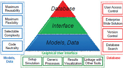
FIGURE G-1 Vehicle modeling tool requirements.
-
that can easily be achieved through combination of configurations and model complexity) is not feasible.
-
Allow users to quickly add their own configurations.
-
Allow users to implement any test data from subsystems, systems, or entire vehicles in the same environment as the models to facilitate the validation process.
Selectable Complexity
Different studies (e.g., fuel efficiency, emissions, drive quality) require different levels of modeling. Throughout a project, the level of model complexity will increase to take into accounts new physical phenomena.
-
Common nomenclature, including naming convention, units. If nomenclature is not consistent, an automated process should be provided to users to easily integrate any legacy code into the agreed upon format.
-
Common model organization to facilitate interactions of different expert models. For example, consistent format between controllers and plant would allow integration between both areas of expertise.
-
Model compatibility check. When used in a large organization, users do not know what models are compatible with each other. For example, a particular gearbox should be used along with a specific torque converter. Using another combination could lead to a software crash—or worse—erroneous results. While the original developers are aware of the potential issue, it is necessary to enforce that when one model is used, it is in conjunction with the other one.
Code Neutrality
While most software companies claim to be able to model any particular plant with different levels of accuracy, some software packages are used mainly for specific applications. As a consequence, different experts will use different packages to model specific plants. One needs to have a plug-and-play platform that allows the user to:
-
Integrate any legacy code from any software package and
-
Run all models in the same environment or through co-simulation.
Graphical User Interface
Setup Simulation
The graphical user interface (GUI) should be able to allow users to quickly set up different simulations, including:
-
Select architecture, model, and data
-
Check model compatibilities to avoid crash or erroneous results
-
Select simulation type, including component evaluation, vehicle fuel efficiency, or drive quality
Generic Processes
When evaluating specific technologies, having consistent processes is critical for proper comparison. Differences in the definitions of processes could lead to discrepancies in results, which could become a significant issue for regulatory purposes. For example, the definition of the term “validation” varies significantly from one engineer to another. In addition clear definition of generic processes (e.g., calibration, validation, tuning) for major tasks throughout a company will lead to increased productivity.
Users should have the ability to easily modify any processes or implement new ones. One could assume that specific processes would be developed and agreed upon for validation, report generation, and so forth for regulatory purposes.
Results Visualization
The GUI should allow users to quickly analyze the simulation.
-
Predefined calculation. Since most tools only record efforts (e.g., torque, voltage) and flows (e.g., rotational speed, current), existing calculations should allow users to quickly calculate powers, energies, efficiencies, and so forth.
-
Predefined plots should be available to quickly analyze the operating conditions of each component or control strategies.
-
Energy balance information should be available.
-
Reports should be automatically generated.
-
All results should be saved along with the assumptions and any files required to rerun the simulation.
-
Any existing calculation, plot, or report should be easily modified by users or new ones should be implemented.
Linkage with Other Tools
As discussed previously, linkage with other tools is compulsory to properly integrate detailed legacy models. While numerous tools exist, the list should include at a minimum MathWorks toolboxes, GT-Power, AMESim, TruckSim, ADAMS, and AVL DRIVE.
Database
User Access Control
The sharing and distribution of proprietary models can be achieved successfully only if their producers can trust that only the proper users will have access to them. User access control is the cornerstone of that trust.
User access control can be used in two ways:
-
Intra-enterprise, to define the access at each process steps. For instance, during the design stage, only the design team can access the model. Once a version is ready, access can be granted to a larger group, such as calibration, testing, and so forth.
-
Extra-enterprise, to define the access to outside users, including suppliers, regulatory committees, and so forth.
Access control should be of at least four types:
-
Producer, for the people who can add and/or modify models and data on the database.
-
Consumers with full access, for people who can download the models and data to run on their computers, but not modify them (or at least not upload them on the database).
-
Consumers with restricted access, who can only run the models remotely on a dedicated server (no access to the models or data themselves).
-
Administrator, who manages access control for everyone.
Users can also be a combination of these types. For example, some people creating models may need to access existing ones, and consumers with full access on some models may have only restricted access on others, or they can access only low-fidelity versions of some models.
Enterprise-Wide Solution
Another requirement for the sharing and distribution of proprietary models is their enterprise-wide accessibility, including for producer and consumer teams spread across the country or even the world for some global companies—for example, a control design team can have members in the United States and England, or a model calibration and validation team might be located hundreds of miles from the model design team.
Up-to-date models should be accessible to all people who have the right access, wherever they are located.
This constraint requires a unique and secure point of access for all users. However, there can be one point of access for intra-enterprise use only in each company and another global one outside, specifically for regulatory purposes.
Version Control
As models and data evolve with time owing to improved data and/or algorithms, or even issues such as new modeling software version compatibility, the need for version control is mandatory for auditing and regulatory purposes. Any study done with those models needs to specify which version was used to ensure 100 percent traceability of the results.
Moreover, version control can also be used intraenterprise as a way to get feedback on the original designs. For example, the model producer can follow which modifications were needed to his model during the calibration and validation process, which can then be used to create a better model next time. Version control can also be used to locate the original designer to get more information about some of the model.
User access control applies on versioning as well. Some users should have access to all model versions, when some others have access only to the latest version and others can only see the history.
Database Search
To maximize the reusability of models, any user should be able to search for an existing one available to them. Search should be available on name and versions of the files, as well as specific criteria, such as, engine technology, displacement, and wheel radius.
The search should also be possible by specific vehicle or project, so that all of the models and data used for a specific application can be found together and eventually run or downloaded on the user’s computer.
Only the models and data that the user has access to should be returned in the search query. As an optional functionality, the search could inform the user that other models exist but are not available and could provide the coordinates of people to contact to request their access.
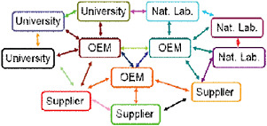
SINGLE VERSUS MULTIPLE TOOLS SELECTION FOR REGULATION
Numerous tools are currently being used by companies, both internally developed and commercially available. For regulatory purposes, consistency between all approaches is critical for a fair comparison. As a result, while legacy code shall be used, a single platform is necessary to ensure proper integration of the different systems. Indeed, due to the large number of companies involved, the models used to simulate a specific application will most likely come from numerous sources. Common tool and formalism are then critical. As shown in Figure G-2, the lack of common nomenclature makes reusability of models among companies very cumbersome.