
THE NATIONAL ACADEMIES
Advisers to the Nation on Science, Engineering, and Medicine
Board on Army Science and Technology
Mailing Address: 500 Fifth Street, NW Washington, DC 20001 www.nationalacademies.org
August 25, 2010
Mr. Conrad F. Whyne
Director
Chemical Materials Agency
5183 Blackhawk Road Edgewood Area Aberdeen Proving Ground, MD 21010-5424
Re: Review of the Design of the Dynasafe Static Detonation Chamber (SDC) System for the Anniston Chemical Agent Disposal Facility
Dear Mr. Whyne:
At your request, the National Research Council of the National Academies established the Committee on Review of the Design of the Dynasafe Static Detonation Chamber (SDC) System for the Anniston Chemical Agent Disposal Facility. The purpose of the committee was to review the SDC design as stated below and in the statement of task, given in Appendix A. The committee was provided with information on the Anniston SDC1200 system that was undergoing testing in Europe. This SDC system is being acquired as an efficient means to destroy mustard agent projectiles and mortar rounds at Anniston Army Depot that could present problems for processing through the existing Anniston Chemical Agent Disposal Facility.
The committee’s general findings and recommendations are given below. Specific findings and recommendations are given in the attached report. All of these findings and recommendations are based on the presentations, drawings, and design documents provided to the committee on March 30, 2010, and April 1, 2010, by the Army and its contractors—URS Corporation and UXB International, Inc.—and on the committee’s subsequent information-gathering activities.1 Together with Mr. Douglas Medville, another committee member, I visited the workshop in Kristinehamn, Sweden, where the unit was being assembled and tested. Before, during, and after the visit, our questions on construction and operation details were answered by the Army and its contractors. It is noteworthy that significant changes to the planned mode of operation of the pollution abatement system (PAS) were being made or contemplated as this report was being prepared, and that only information received as of June 27, 2010, has been considered by the committee. However, no changes in the overall design of the SDC system to be installed at Anniston from what is described in this report are anticipated.
The SDC system being readied for installation at Anniston is the eleventh to be manufactured and operated around the world and will be among four used to destroy chemical weapons. However, the Anniston unit will be the first to process chemical munitions in the United States. The committee was also provided with information on the performance of the Dynasafe SDC2000 installed at Gesellschaft für Entsorgung von Chemischen Kampstoffen und Rüstungs-Altlasten (GEKA), which has been in operation at Munster, Germany, since April 2006. By April 2008, this SDC system had destroyed 28,000 World War I and World War II chemical munitions, and since then has primarily been destroying conventional munitions. 2 It is similar in design to the SDC1200 to be installed at Anniston Army Depot. The GEKA system has demonstrated a destruction and removal efficiency of greater than nine nines (99.9999999 percent) for mustard agent while meeting German environmental regulation requirements (NRC, 2009a).3 Because the GEKA system has operated effectively and safely for a number of years and information on its design and operation was available, the committee focused on any impacts that might be expected from differences between the GEKA and Anniston systems. The review examined the system for feeding the munitions to the detonation chamber, the detonation chamber itself, the metal scrap discharge system, and the PAS (the latter must reduce emissions below U.S. environmental regulatory limits).
This letter report provides the technical information necessary to support the general and specific findings and recommendations of the committee. The analysis satisfies the tasks delineated in the following extract from the committee’s complete statement of task, given in Attachment A:
…Obtain detailed information on the design of the Anniston Dynasafe SDC1200 CM system and review and comment on the design of the system with emphasis on the pollution abatement system (PAS). Determine the design basis for each unit operation and review materials of construction. Compare the design of the PAS being designed for Anniston with that currently in use at the GEKA facility in Munster, Germany and identify all differences. Evaluate any potential impacts of these differences.
Obtain requirements for agent destruction within the Static Detonation Chamber (SDC) system and for emissions from the PAS. Evaluate and comment on the ability of the planned SDC system to meet these requirements.
The committee’s general findings and recommendations are the following:
General Finding 1. The SDC1200 system to be used at Anniston Army Depot offers a safe and effective method for destroying reject mustard agent munitions that could otherwise be difficult to disassemble safely through the machinery at the Anniston Chemical Agent Disposal Facility. Note, however, the concerns to be addressed by the Army regarding operation of the spray dryer and management of dioxin-and furan-containing waste as described in the following General Findings and Recommendations.
General Recommendation 1. The Army should use the Dynasafe system to destroy the reject mustard agent munitions from the Anniston Chemical Agent Disposal Facility, provided that the factory acceptance testing at Kristinehamn and the preoperational testing at Anniston are satisfactorily completed and the system receives a Resource Conservation and Recovery Act permit modification from the Alabama Department of Environmental Management for operation at Anniston Army Depot and Department of Defense Explosives Safety Board approvals.
General Finding 2. The committee was not convinced the thermal oxidizer in the pollution abatement system for the Dynasafe SDC1200 for Anniston will sufficiently oxidize all the organics, including dioxin and furan precursor compounds, to minimize formation of dioxins and furans in the downstream spray dryer.
General Finding 3. The committee did not find a precedent for using a spray dryer as a rapid quench to control formation of dioxins and furans (polychlorinated dibenzo-p-dioxins and polychlorinated dibenzofurans) as proposed by Dynasafe. The hot gas from the Dynasafe SDC1200 at Anniston in the spray dryer of the pollution abatement system must be quenched to below 200ºC rapidly to minimize dioxin and furan formation. Dynasafe has no previous experience in using a spray dryer for this purpose. However, the activated carbon beds in the pollution abatement system should adequately control dioxin and furan emissions from the stack.
General Recommendation 2. Computational fluid dynamics modeling should be performed to verify satisfactory performance of the spray dryer in the pollution abatement system of the Dynasafe SDC1200 at Anniston. Modeling of this complicated three-phase system might be difficult, but the modeling should attempt to verify uniform gas flow entering the spray section, proper dispersion of the scrubber liquid in the gas, rapid quenching, minimal buildup on the spray dryer walls, and the formation of dry, flowable solids.
General Recommendation 3. The Army and its contractors should develop backup plans in the event that the spray dryer for the Dynasafe SDC1200 system to be installed at Anniston Army Depot does not adequately minimize dioxin and furan formation. Options include installing a conventional rapid quench similar to the one used at GEKA and investigating how to dispose of activated carbon containing these compounds. The Army and its contractors should have a means of disposing of activated carbon and other secondary wastes that are produced in the pollution abatement system and may be contaminated with dioxins and furans.
General Finding 4. Although Dynasafe has some experience in spray drying spent scrubber brines, its ability to effectively reduce this particular brine to dry, flowable solids has not yet been demonstrated.
General Recommendation 4. The Army and its contractors should test the spray dryer during preoperational testing at Anniston to develop suitable conditions for reducing scrubber brine to dry, flowable solids.
General Finding 5. The materials of construction for the Dynasafe SDC1200 are the same or very similar to the materials that have been used for the SDC2000 at GEKA, which has been in operation since 2006. The committee found no cause for concern regarding the anticipated performance of the materials of construction for the Anniston installation.
More specific findings and recommendations are provided in the detailed analysis that follows.
Sincerely,
![]()
Richard J. Ayen,
Chair
Committee to Review the Design of the Dynasafe Static Detonation Chamber (SDC) System for the Anniston Chemical Agent Disposal Facility
Detailed Analysis of the Design of the Anniston Static Detonation Chamber
INTRODUCTION
The Army is in the process of destroying projectiles and mortars that contain the chemical agent mustard at the Anniston Chemical Agent Disposal Facility (ANCDF) located on the Anniston Army Depot (ANAD) in Anniston, Alabama. It has already collected 246 leaking and 61 rejected projectiles and mortars from among the munitions that have been processed, and based on statistics, anticipates that more rejects will be collected before the operations are completed. The “leakers” are sealed in overpacks and returned to storage. The “rejects” are munitions that could not be disassembled robotically in the linear projectile-mortar disassembly machine because the nose plug, burster, or burster well could not be removed. In some cases, the burster has broken and part of the burster remains in the well. As reject munitions become apparent, they are returned to a dedicated storage igloo to await future disposal. Were the leakers and rejects to eventually be processed through the ANCDF, it would require that they be disassembled manually by workers wearing personnel protective equipment known as demilitarization protective ensemble suits. This operation nonetheless would expose the operators to a high safety risk.
Rather than exposing the workers to this additional risk, the Army will use an explosive detonation technology (EDT) to destroy the munitions without disassembling them. The particular EDT system that the Army plans to use is a static detonation chamber (SDC) system manufactured by the Swedish company, Dynasafe AB. The detonation chamber is conceptually illustrated in Figure 1. It shows the munitions dropped into the heated, thick-walled detonation chamber and resting on a scrap bed of hot metal fragments from previously processed munitions. The heating of the explosives in the munitions and/or the pressure generated from the heated liquid agent contents eventually cause the munitions to rupture and add to the scrap bed, which is periodically reduced by a chamber tipping procedure.
The complete SDC system contains a munitions handling and loading system and a detonation chamber with a pollution abatement system (PAS) and a metal scrap disposal system. This SDC system was fabricated in Germany and, as this report was being prepared, was being assembled and tested in Kristinehamn, Sweden. When testing was completed, the system was to be shipped to ANAD. The various units are housed in between 20 and 25 ISO (International Organization for Standardization) shipping containers. They will remain in these containers and they will be abutted, stacked, and connected to form a complete system. These containers also will serve as secondary containment for the system. This system could be disassembled after operations are completed at ANCDF and moved to another site or used to destroy conventional munitions. As mentioned in the cover letter, Dynasafe has produced ten similar systems that have been used throughout the world. The system for Anniston will be the eleventh. As of April 2010, two of the eleven systems had been used to destroy chemical weapons. With the ongoing installations in Japan and at Anniston, the number put to this use increases to four. However, no two of these systems are identical, because specific
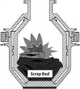
FIGURE 1 SDC cutaway showing basic detonation chamber construction and concept of operation. SOURCE: Tim Garrett, Site Project Manager, ANCDF and Charles Wood, ANCDF Deputy Operations Manager, URS, “Static detonation chamber (SDC),” presentation to the committee, March 30, 2010.
customer requirements have been implemented in each project.4 Also, the Army has two Dynasafe chambers—not complete explosive destruction technology systems—installed at its Munitions Assessment and Processing System facility at the Aberdeen Proving Ground in Maryland (NRC, 2009a), which processes chemical munitions recovered from burial sites, and which makes the Army familiar with, and comfortable with, Dynasafe detonation chambers.
The Army has requested the National Research Council through the auspices of the Board on Army Science and Technology to assemble a committee to
…Obtain detailed information on the design of the Anniston Dynasafe SDC1200 CM system and review and comment on the design of the system with emphasis on the pollution abatement system (PAS). Determine the design basis for each unit operation and review materials of construction. Compare the design of the PAS being designed for Anniston with that currently in use at the GEKA facility in Munster, Germany and identify all differences. Evaluate any potential impacts of these differences.
Obtain requirements for agent destruction within the Static Detonation Chamber (SDC) system and for emissions from the PAS. Evaluate and comment on the ability of the planned SDC system to meet these requirements.
The complete statement of task is presented in Attachment A. This report contains the committee’s detailed findings and recommendations. The general findings and recommendations are presented in the cover letter.
REGULATORY AND PERMITTING BACKGROUND, EMISSIONS LIMITS, AND OTHER PERFORMANCE REQUIREMENTS
The ANCDF is designed to dispose of chemical nerve agents, mustard agents, agent-containing munitions, contaminated refuse, ton containers, liquid wastes, and explosive and propellant components. From a regulatory perspective, the facility is considered a hazardous waste disposal facility. The ANCDF operates under a Resource Conservation and Recovery Act (RCRA) permit, AL3 210 020 027, issued pursuant to the Code of Alabama 1975 §§ 22–30–1 et seq. ANCDF must also comply with any ANAD Clean Air Act Permit.
On March 19, 2010, ANAD filed an application with the Alabama Department of Environmental Management (ADEM) to modify its RCRA permit to allow the addition of one permitted miscellaneous (RCRA Subpart X) unit—an SDC, which will enable the thermal treatment of both chemical and conventional waste munitions.5 Due to the varied nature of these units, requirements for construction and operation of Subpart X miscellaneous units are generally established in the permit. However, ADEM regulations require that miscellaneous units do not release materials that may adversely affect human health or the environment if waste constituents migrate in the groundwater or subsurface environment, surface water or wetlands or on the soil surface, or in the air. In addition, the terms and conditions for a miscellaneous unit permit must include the requirements for other types of treatment units, as appropriate for the miscellaneous unit being permitted.6
As set forth in the application and accompanying regulatory filings, this miscellaneous unit will need to meet the requirements for a hazardous waste incinerator. Under the regulations, RCRA regulations concerning hazardous air emissions do not apply to hazardous waste incinerators that demonstrate compliance with the Hazardous Waste Combustor Maximum Achievable Control Technology (MACT) requirements by conducting a comprehensive performance test, submitting to the ADEM a notification of compliance, and documenting compliance under the ADEM air quality regulations.7
As stated in the application for modification, ANAD will comply with National Emission Standards for Hazardous Pollutants Hazardous Waste Combustor MACT
requirements.8,9 This rule stipulates emission standards based on the performance of maximum achievable control technology, commonly referred to as MACT standards, because the EPA used the MACT concept to determine the levels of emission control.10 In essence, MACT standards ensure that all major sources of air hazardous air pollutant emissions are controlled to a level achieved by the best controlled and lowest emission sources in each category. The EPA found that this approach assures citizens that each major source of toxic air pollution is being effectively controlled.11 The MACT standards limit emissions of chlorinated dioxins and furans,12 carbon monoxide and hydrocarbons, toxic metals (including mercury and arsenic), hydrogen chloride and chlorine gas, and particulate matter. The ANAD application for RCRA permit modification states that performance standards to be met are as follows:
-
Destruction and removal efficiency (DRE) of 99.9999 percent for mustard agent (HD/HT);
-
Emissions from products of incomplete combustion from the stack such that the CO level in the stack, corrected to 7 percent O2, are not to exceed 100 ppm, dry volume, over a rolling hourly average;
-
Emission levels for mustard agent, measured by an automatic continuous air monitoring system (ACAMS) installed at the stack, are not to exceed a maximum stack emission (mg/m3) of 0.006 rolling hourly average and 0.03 instantaneous; and
-
Particulate matter emissions from the common stack, corrected to 7 percent O2, are not to exceed 0.013 grains per dry standard cubic foot (dscf).13
The final permit will establish the emissions limits for the following parameters in terms of grams per second (g/s):
-
HCl emissions;
-
Metal emission rates for antimony, arsenic, barium, beryllium, boron, cadmium, chromium, cobalt, copper, lead, manganese, mercury, nickel, phosphorus, selenium, silver, thallium, tin, vanadium, and zinc;
-
Volatile, semivolatile, and total organic compound emissions;
-
Dioxin/furan emissions; and
-
Energetic emissions.14
These emission limits will be established after emission testing is completed and the results are compared with the Human Health Risk Assessment.
During normal operations, the established emissions limits must be met by limiting the overall feed rate into the SDC. ANAD will submit a request to modify the permit to include numerically specified data for the above parameters not later than 90 days following the emissions test.15
As part of the application for a RCRA permit modification, ANAD filed a proposed emissions test plan. The test plan defines operating conditions and munitions feed rates that will be used to determine SDC performance in accordance with ADEM hazardous waste incinerator standards. ANCDF is proposing two emissions tests for the SDC system, one using worst-case mustard-agent-filled munitions and the other using conventional munitions. These tests must be done at Anniston after the system is installed there. The mustard-agent-filled munitions emissions test was developed to establish an agent feed limitation and to demonstrate a DRE of ≥99.9999 percent while processing 4.2-in. mortars fed up to 12 mortars per hour, which is equivalent to 72 pounds per hour (lb/hr) of mustard agent and/or 1.7 lb/hr of energetics. The emissions test should also demonstrate an allowable rolling average stack concentration for mustard agent of <0.006 mg/m3 and an allowable instantaneous stack concentration for mustard agent of <0.03 mg/m3. As described in Section 1.0 of the emissions test plan (Westinghouse Anniston, 2010), the overall goals of the emission tests are to demonstrate that emissions are less than the screening levels established in the Human Health Risk Assessment for the site and to verify that the SDC system does not pose an unacceptable risk to public health and the environment when operating at normal conditions.
In addition to complying with any Clean Air Act permit requirements, the generation, storage, treatment, and disposal of secondary wastes (i.e., wastes generated during the preparation and treatment of waste munitions in the SDC) must also comply with all applicable RCRA characterization and management regulations, including compliance with any waste control limits for mustard agent and standards for all other hazardous constituents, as established in the RCRA permit modification.
Finding 1. As detailed in documentation provided to the committee, the Army appears to be complying with all required procedures for obtaining permits for the planned static detonation chamber facility.
DESIGN OF THE DYNASAFE SDC SYSTEM FOR ANNISTON
Overall Process
This section provides a brief overall description of the SDC system. The various operations are described in greater detail in subsequent sections. The SDC system is being fabricated by Dynasafe with most components installed in ISO containers and as such delivered to Anniston. It will be installed on a concrete foundation near the existing ANCDF and housed in a Sprung structure. Most of the system will remain within the ISO containers, which will serve as secondary containment. The system will be operated 10 hours per day 5 days a week.
The flow of materials through the process is shown in Figures 2a and 2b. The munitions scheduled to be destroyed each day will be delivered at the beginning of each morning. First, each munition is strapped into a preformed polyethylene tray and then manually placed on the input conveyor (Dynasafe, 2010).16 Each tray will contain from one to four munitions depending on the physical size of the munitions and the nature and quantity of the contained energetics.17 After loading the munitions onto the conveyor, personnel will vacate the Sprung structure and move to the control facility. The remainder of the process is controlled remotely from the control room.
Each loaded tray is conveyed to the munition lift and raised to the top of the SDC (Dynasafe, 2010). The first blast door is opened and the tray is pushed into loading chamber 1. This door is closed and the second blast door is opened. The tray is pushed from loading chamber 1 onto a cradle in loading chamber 2 above the detonation chamber. In this position, the cradle assembly blocks the opening into the detonation chamber below. The cradle is rotated 90 degrees and the munition tray drops into the chamber. Loading chambers 1 and 2 are shown in Figure 2a, with loading chamber 2 shown in both its horizontal (loading mode) and vertical (discharging) positions.
The detonation chamber is double-walled with an air space between the two walls. It is split into upper and lower parts. When in operation, the two parts are sealed together with a hydraulically operated locking ring.
The inner wall, which receives damaging impacts from fragments, can be replaced. The chamber is heated electrically at the bottom, as indicated in the cutaway view shown in Figure 3, and maintained at an operating temperature of 1022ºF (550ºC), although the temperature will spike briefly above this value when a munition detonates or deflagrates. Agent contained within a munition cannot survive as agent when exposed to this temperature for more than 15 minutes.18 The burster charge in the projectile or mortar will either deflagrate or detonate as the munition heats up and will burst the munition open. Also upon heating, the liquid agent in the munition evaporates, generating enough
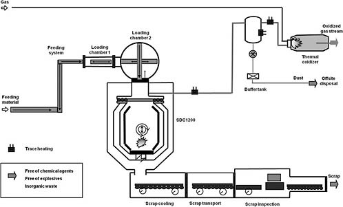
FIGURE 2a Process flow diagram for front components of Dynasafe SDC1200 installation for Anniston Army Depot. SOURCE: Adapted from personal communication between Holger Weigel, Vice President, Dynasafe International, and Managing Director, Dynasafe Germany, and Richard Ayen, committee chair, May 12, 2010.
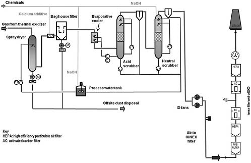
FIGURE 2b Process flow diagram for back-end pollution abatement system components of Dynasafe SDC 1200 installation for Anniston Army Depot. SOURCE: Adapted from personal communication between Holger Weigel, Vice President, Dynasafe International, and Managing Director, Dynasafe Germany, and Richard Ayen, committee chair, May 12, 2010.
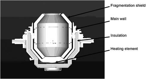
FIGURE 3 Cross section of lower part of detonation chamber of the Dynasafe SDC1200 for Anniston Army Depot. SOURCE: Dynasafe, 2010.
pressure inside the munition to displace the burster well and allow the liquid (now a vapor) to leak out. Any agent, whether still contained within the munition or escaped into the chamber, does not survive as agent under the stated operating conditions.
As the scrap metal accumulates in the detonation chamber, the control system counts the number of munitions fed since the last emptying event. From prior experience, it is known how many of each type of munition can be accommodated within the chamber. When this limit is reached, the control system will not allow the feeding of additional munitions. In addition, operations are planned such that the scrap metal is discharged at the beginning of each day’s operations. In this way, it is certain that the scrap is suitable for unrestricted release.19 Some of the scrap is retained to protect the bottom of the chamber. To empty the chamber, the bottom part of the detonation chamber is disconnected from the top part. Then, the bottom part is tipped about 150 degrees to allow most of the hot scrap to drop onto a discharge conveyor.20 The scrap moves along three successive conveyors by shaking. The conveyor system is long enough to hold three days of scrap production. To satisfy the requirements of the Chemical Weapons Convention, as implemented by the Organisation for the Prohibition of Chemical Weapons, the scrap is inspected after cooling.
The off-gases are transferred to the PAS. It is expected that more than 99.99 percent of the agent will have been destroyed at this point (NRC, 2009a). However, the gases will contain products such as CO and hydrogen. To complete the oxidation, the off-gas is passed through a thermal oxidizer operating at 1100ºC or higher with excess
oxygen. At this point, the agent destruction is expected to be greater than 99.9999 percent DRE (NRC, 2009a). The off-gas from the thermal oxidizer is passed to a spray dryer, where it is cooled from 1100º to 180ºC.
Aqueous scrubbers are employed further downstream in the PAS to remove certain materials from the process off-gases. Because the Army has chosen to avoid producing liquid waste, the spent solution from these scrubbers must be converted to nonliquid materials to avoid overall generation of liquid waste from the installation. The spent scrubber solution is therefore converted to water vapor and dry solids in the spray dryer, with the particulate solids then removed in a baghouse. Dynasafe also expects this spray dryer to serve as a rapid quench for control of dioxin and furan formation.21,22 The gas temperature is then further reduced from 175ºC to 78ºC in an evaporative cooler. The remaining volatile components are removed by passing the off-gas through acid and neutral (pH 6.7) scrubbers.23 Finally, the gas stream is filtered through two activated carbon filter banks. The first carbon bank contains sulfur-impregnated carbon to remove any mercury that may have been present in the mustard agent.
Munitions to Be Processed in Anniston SDC1200
The munitions to be destroyed at Anniston include currently stored and overpacked 4.2-in. mortar rounds and 105-mm projectiles plus all rejects that will be generated during remaining operation of the ANCDF. A reject is a munition that cannot be processed in a normal manner through the ANCDF and can include 105-mm projectiles, 4.2-in. mortar rounds, and 155-mm projectiles. All of the munitions that are to be processed in the SDC1200 are filled with mustard agent (either HD or HT); their dimensions are summarized in Table 1.
TABLE 1 Munition Dimensions and Weights
|
Munition and Fill |
Length (in.) |
Diameter |
Total Weight (lb) |
|
M60 cartridge (HD) |
31 |
105 mm |
32.7 |
|
M110 projectile (HD) |
22.8a |
155 mm |
94.6 |
|
4.2-in. mortar cartridge, M2 (HT) or M2A1 (HD) |
18.0 |
4.2 in. |
24.7 |
|
a Projectile body only without lifting ring. SOURCE: Personal communication between Tim Garrett, Site Project Manager, ANCDF, and Harrison Pannella, NRC, study director, April 5, 2010 and May 19, 2010. |
|||
A variety of containers are available to overpack and, if need be, to double overpack any leaking and reject munitions. These overpacks and their dimensions are listed in Table 2.
TABLE 2 ANCDF Overpack Container Data
|
Overpack Type |
Used for |
Length (in.) |
Flange Diameter (in.) |
Tube Diameter (in.) |
Empty Weight (lb) |
|
12 × 56 SRCa |
Double overpacking any munition |
57.25 |
15.12 |
12 |
133 |
|
7 × 27 SRC |
105-mm or 4.2-in. |
28.25 |
10.5 |
7 |
52 |
|
5.4 × 36 M55 R-SRC |
105-mm or 4.2-in. |
36.0 |
6.0 |
5.4 |
21 |
|
9 × 41 SRC |
155-mm |
42.5 |
13.5 |
9 |
99 |
|
M13 PCC |
105-mm or 4.2-in. |
22.5 |
7.75 |
7 |
16 |
|
M16 PCC |
105-mm or 4.2-in. |
42.75 |
8.5 |
7 |
22 |
|
PIG |
105-mm |
38.0 |
9.0 |
6.63 |
50 (est.) |
|
NOTE: SRC, single round container; PCC, propellant charge container; and PIG, container for M1 Gas ID Set. a There are no Anniston munitions that are currently double overpacked within the 12 × 56 SRC. SOURCE: Harley Heaton, Vice President, Research, UXB International, Inc., e-mail response to committee question, April 14, 2010. |
|||||
All of the leaker and reject munitions at ANAD and their overpacks will fit into a standard polyethylene loading tray that is 1,510 mm (59.44 inches) long, 435 mm (17.12 inches) wide, and 103 mm (4.06 inches) high, described in the next section, on the SDC feed system.
SDC Feed System
Processing at Anniston
For the system to be used at Anniston, the munitions or munitions in overpacks are placed into polyethylene loading trays and strapped in place to secure them. From one to four munitions may be placed in a tray, depending on the munitions’ explosive content.24 The use of trays provides a consistent package to be delivered to the feed system, preventing jamming or hanging up of munitions and overpacks. Conveyors move the munitions to a lift that elevates the trays to the entrance gate to loading chamber 1, above the SDC1200 detonation chamber. An airtight blast gate at the entrance to loading chamber 1 is partially opened hydraulically. Loading chamber 1 is vented to a process ventilation system. This system is kept under negative pressure by means of induction fans, and the air it collects is passed through particulate filters and activated carbon beds,
then vented to the atmosphere. Thus, partially opening the blast gate at the entrance to loading chamber 1 admits fresh air from inside the Sprung structure, flushing the chamber. The blast gate is then opened completely. An electrical pusher moves the tray with its munitions into the loading chamber. The entrance gate to loading chamber 1 is then closed and a gastight, sealed gate (gate 2) between loading chambers 1 and 2 is opened. The tray is then pushed into a cradle inside loading chamber 2. Gate 2 is closed. A replaceable plug, called a fragment valve, separating gate 2 from the SDC chamber is lifted. When the system is viewed as shown in Figure 2a, the tray enters loading chamber 2 inside the cradle from the left side. The cradle, including the fragment valve, is then rotated 90 degrees counterclockwise so that what was the side entrance to the loading cradle becomes the bottom exit. Neither the exit from the loading chamber nor the entrance to the detonation chamber has a gate, so when the exit of the loading chamber is aligned with the entrance to the detonation chamber, the tray will drop into the detonation chamber.
The cradle is then rotated back to a horizontal position. A hydraulic cylinder presses on the fragment valve to hold it in place and to seal off and protect loading chamber 2 from the detonation chamber.
Processing at GEKA
At GEKA, munitions are placed in sealed, airtight plastic bags, then into cardboard boxes manually. The boxes are placed in an elevator and transported to the top of the 8-m-high SDC2000. Leaking munitions are placed in a second sealed, airtight plastic bag rather than in overpacks. Boxed munitions are fed into the SDC2000 by being passed through two offset loading chambers, one above the other. Each chamber has its own hydraulically operated door and inflatable seal. The upper loading chamber has airlock doors and the lower loading chamber has a door separating it from hot blasts from the SDC2000 detonation chamber below.
Boxed munitions are pushed into the loading chambers with hydraulic arms. They move from one chamber to the next and are then dropped onto the detonation chamber’s heated scrap bed, about 2 m below the second loading chamber.
Differences Between Processing at GEKA and at Anniston
Leaking munitions at Anniston will be placed in one of the overpacks described in Table 2. As shown in that table, the largest permissible munition overpack is a 12 × 56 double overpack SRC. As this report was being prepared, no munitions at Anniston had been placed in such an overpack. Although the overpack will fit into the munition tray, the gap between each end of the overpack and each end of the tray would be only an inch or so. If such an overpack is needed, it is planned to cut the tray in half laterally and to place a spacer between the halves to increase the tray length.
To accommodate the munition overpacks to be used at Anniston, the capacity of the loading conveyors and the volume of the loading chambers have been increased relative to those at the GEKA facility. For example, while the second loading chamber at GEKA has a volume of 0.5 m3, the volume of loading chamber 2 at Anniston is 4.5 m3. At GEKA, the first loading chamber was positioned above the second one, with both
chambers offset from the top of the blast chamber. In Anniston, the loading chambers are configured end to end, with loading chamber 2 placed directly above the detonation chamber. The loading chambers were redesigned to accommodate the 12 × 56 double overpack and to improve the transport of material to the detonation chamber. The redesign also allows the boxed munitions to be rotated and dropped directly into the chamber.
An improvement at Anniston is the use of a cradle to rotate the strapped munition package before it is placed into the detonation chamber opening; this eliminates the possibility that munitions might tilt or become caught in the vertical inlet opening. This rotating cradle approach is a relatively new concept for Dynasafe. Only one other system, used in an SDC1200 recently started up in Japan, has employed this concept. The rotating cradle in that system has performed well. However, relatively few munitions, several tens as opposed to hundreds or thousands, had been fed through that system as this report was being developed. Therefore, extended operation of the rotating cradle, including the fragment valve, should be carried out during the preoperational testing at Anniston Army Depot, using overpacks that will be fed during subsequent munition destruction operations.
The door gaskets between feed chambers 1 and 2 have been redesigned and made smaller to facilitate maintenance and replacement and to reduce the amount of debris that accumulates around the gaskets.
Finally, for safety and environmental control purposes, both loading chambers at Anniston are under negative pressure and have secondary containment to retain agent in the event of a primary containment leak. The negative pressure is generated by induction draft fans in the process ventilation system. At the entrance throat to the fans, the pressure is negative 0.72 psig. At GEKA, the loading chambers are operated at atmospheric pressure. The loading chambers at both sites are constructed from MA 253 stainless steel, also known as RA-253, which has performed satisfactorily at GEKA.25
Other safety features that will be used at Anniston but have not been used at GEKA include (1) using a hydraulic cylinder to remove munitions from loading chamber 2 by moving them back to loading chamber 126; (2) heating to decontaminate loading chamber 2 with air at 500ºC for no less than 24 hr; and (3) decontaminating loading chamber 1 using a high-pH water solution.27 Loading chamber 2 is normally operated at 40-50ºC, and the temperature is not allowed to exceed 60ºC. The temperature is held at 40-50ºC overnight and on weekends.28
Finding 2. The feed system at Anniston is different from the one at GEKA. However, subject to the results of mechanical shakedown testing still to be done, the Anniston
Dynasafe feed system can be expected to function at least as well as GEKA’s feed system.
Recommendation 1. Extended operation of the rotating cradle with overpacked munitions and operation of the hydraulic fragment valve at the interface between loading chamber 2 and the top of the detonation chamber under realistic (hot) conditions should be demonstrated in preoperational testing at Anniston Army Depot.
Detonation Chamber
Processing at Anniston
The detonation chamber is approximately spherical and consists of upper and lower parts (Dynasafe, 2010). The upper part, shown in the cutaway illustration provided in Figure 4, comprises approximately the upper third of the chamber; at its top, it is attached to the outlet flange of loading chamber 2. Connections for admitting process air , venting off-gas, and pressure and temperature measurement leads are located in this upper part. The lower part is shown in the cutaway view in Figure 3. This lower part consists of, from inside to outside, an inner 4-in.-thick fragmentation shield, a 2.75-in.-thick main wall, a layer of insulation, and a 3-mm-thick metal outer shell. The fragmentation shield, which is replaceable, and the main wall are constructed from MA 253 stainless steel, also known as RA-253.29
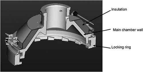
FIGURE 4 Cross section of the upper part of the detonation chamber of the Dynasafe SDC1200 for Anniston Army Depot. SOURCE: Dynasafe, 2010.
A fatigue analysis for the main chamber and the fragmentation shield has been carried out. This analysis was done for destruction of 155-mm projectiles, the largest munition in inventory. The fatigue analysis assumed detonation of the munition as opposed to the more anticipated deflagration.30 The predicted fatigue lifetime exceeded 300,000 detonations for the fragmentation shield and approached 900,000 detonations for the main chamber.
During operations, the upper and lower parts are locked together with a hydraulic locking ring. Three pressurized pneumatic gaskets inflated at up to 217 psi seal the upper and lower parts of the detonation chamber. The gaskets are made of a silicone material and are reported by Dynasafe to be very reliable. They are replaced once a year as a precautionary measure.31 When processing munitions, hot (500°C) air is fed to the chamber to help destroy agent and energetics. This air is supplied from the operation’s process air system, which can supply compressed air at pressures of up to 87 psi. The pressure and flow rate are adjusted to the desired levels, and the air is fed into (pushed through) a 50-kW three-phase electric heater. The heater vessel has a design temperature of 1000°F and a design pressure of 160 psi. The heated air passes into the upper part of the chamber and is directed downward toward the scrap bed by means of a nozzle. The heater is in operation whenever munitions are being fed.32
As the munitions heat up, the burster charge in the projectile or mortar will either deflagrate or detonate and burst the projectile open. In the event no explosives were contained in a munition, when the liquid agent in the munition heats and evaporates, it generates enough pressure inside the munition to displace the burster well and allow the liquid (now a vapor) to leak out. Munitions are fed to the chamber until the scrap fills about half the chamber, which typically happens after one day of operation. The feeding of munitions is stopped and the chamber is held at 550°C (1022°F) until the following morning, rendering the scrap suitable for release for unrestricted use, formerly denoted as 5X. Most of the scrap is then removed.
To remove the scrap, the locking ring is rotated to the open position and the lower part of the chamber is lowered about 19.7 inches using hydraulic mechanical lifting jacks. The lower part of the chamber is then tipped to about 150 degrees from the vertical using another hydraulic motor, thereby discharging most of the scrap (Heaton, 2010). The falling scrap passes through a funnel, then a scrap chute, and discharges onto the first of the three scrap conveyors. The detonation chamber operates at 550°C, and it is held at this temperature during the night and over weekends to (1) minimize transient stresses on the chamber, thus improving longevity; (2) to assure that the scrap left in the chamber overnight is in a 5X (decontaminated) condition; and (3) to allow restarting the unit in the morning or on Monday without having to wait for it to come to operating temperature.33
As this report was being prepared, the ability of the chamber to withstand a given number of explosions involving a specific amount of explosives without deforming or
failing was being reviewed by the Department of Defense Explosives Safety Board (DDESB). The review involves taking physical measurements before and after explosions from energetics having higher explosive weights than were expected to be experienced during disposal operations. The results are then used to place a limit on the net explosive weight of individual charges of munitions that could be fed to the chamber. This is a thorough, in-depth process that is carried out by the Army’s top experts on explosives handling. Testing for deformation after setting off charges with a 1.25-kg net explosive weight of TNT equivalent was carried out in May 2010.34 Dynasafe has stated that the chamber meets the requirements of the recently published American Society of Mechanical Engineers (ASME) Code Case for impulsively loaded vessels (Code Case 2564), which applies to the design of pressure vessels subject to repeated impact loadings (NRC, 2009a). Dynasafe also carried out fatigue analysis calculations (previously mentioned) and computational fluid dynamics modeling. As this report was being written, the DDESB was reviewing design methodology. Dynasafe has stated that the DDESB is more interested in adherence to Army Technical Manual TM5–1300 requirements than to ASME code cases. The DDESB will eventually issue a letter indicating conditions under which the system, including the chamber, can be operated. Most importantly, the letter will indicate an upper limit to the net explosive weight of individual charges of munitions to the chamber. The Dynasafe explosive capacity design aims to obtain an upper limit of at least 1.0 kg TNT equivalent of mass detonating material (can be sympathetically detonated, HAZMAT Class 1.1 explosive) or at least 3.0 kg TNT equivalent of non-mass-detonating material (Dynasafe, 2010).
Processing at GEKA
At GEKA, the detonation chamber is also approximately spherical. The maximum inside diameter is 2 m, the inside height is 2 m, and the total volume is 4.5 m3.35 The locking ring that attaches the detonation chamber to the second loading chamber is at the very top of the detonation chamber. The wall has a total thickness of 15 cm and consists of two 7.5-cm-thick layers of MA 253 stainless steel.36 The inner wall is not replaceable. The electrical heating elements are located between the two metal walls of the chamber on the lower sides. The munitions are destroyed in the same manner as at Anniston. When the desired amount of scrap has accumulated in the chamber, it is tipped about 180 degrees instead of 150 degrees. A baffle near the discharge opening retains the amount of scrap needed to protect the bottom of the chamber when destruction of munitions is resumed.
The detonation chamber in use at GEKA and that planned for Anniston have the same function but notable differences in design:
-
The chamber at GEKA is larger. The inner volume of the SDC1200 detonation chamber at Anniston is 1.9 m3 and that of the SDC2000 at GEKA is 4.50 m3.37
-
The walls are constructed differently. The innermost layer of the GEKA chamber is 7.5 cm thick and is not replaceable. The innermost layer of the Anniston chamber, now called the fragmentation shield, is 4 in. (10.16 cm) thick and is replaceable. It is anticipated that replacement would be necessary only after at least several years of operation.
-
Both chambers have upper and lower parts that separate to allow emptying. However, the separation point is significantly lower for the Anniston chamber to facilitate use and replacement of the removable fragmentation shield.
-
The electrical heating elements are in different locations. At Anniston they are on the bottom of the chamber, in direct contact with the outside of the main metal wall; at GEKA, they are located between the two metal walls of the chamber on the lower sides.
However, many features are the same for the two detonation chambers, including the locking ring, the jack screws for raising and lowering the chamber, the various hydraulic motors, the inflated gaskets for sealing the upper and lower parts together, and the shielding to isolate hydraulic cylinders and jack screws from dust. Both chambers are constructed from MA 253 stainless steel, and the GEKA chamber has destroyed mustard-filled munitions with no material of construction problems since start-up of the system in 2006.
Finding 3. Overall, the changes away from the design of the detonation chamber used at GEKA are not expected to adversely affect the performance of the detonation chamber of the Dynasafe SDC1200 planned for use at Anniston. The detonation chamber at Anniston is thus expected to perform at least as well as the SDC2000 detonation chamber in use at GEKA.
Scrap Discharge System
Processing at Anniston
Scrap from the detonation chamber is unloaded each morning through a chute onto the first of four linked conveyors (Dynasafe, 2010). The first three conveyors are inclined upward and are vibrated in a fashion that causes the scrap to move slightly uphill. Each conveyor overlaps the next and the scrap thus drops from one conveyor to
the next. The entire scrap conveyor system is contained within a gastight ventilation hood. Ventilation air is passed over the conveyors opposite to the flow of the scrap to cool the scrap and remove dust. The conveyors are equipped with stop plates to control the flow of the scrap, providing enough retention time to cool the scrap to below 176ºF. For most of the time, the stop plates are held flush with the roof of the conveyor tunnel. When scrap needs to be held back, the plates are rotated such that the trailing edge (downstream with respect to the scrap flow) drops nearly to the conveyor surface and the plates are vertical. Openings between the second and third conveyors allow dust to fall into a collection box.
Toward the end of the scrap discharge conveyor system, the scrap drops from the last of the three vibrating conveyors onto the lower end of the fourth conveyor, an upwardly angled belt conveyor. At this point, the belt conveyor housing contains a window for inspecting the scrap.38 The conveyor housing that has the window can be lifted to remove a seemingly intact munition if required. With proper precautions, manually removing the munition should not be a dangerous step. After residing at the 550ºC operational temperature in the detonation chamber, the C-C, C=C, and other chemical bonds in the energetic materials and agent would have been broken such that these materials would be destroyed through deflagration and/or pyrolysis. However, the munition can be marked and sent back through the detonation chamber as a precautionary step. To meet the requirements of the Chemical Weapons Convention as implemented by the Organisation for the Prohibition of Chemical Weapons for munition deformation, it would then need to be cut apart. The fragmented scrap on the last conveyor is subsequently dropped into a scrap container.
Processing at GEKA
At GEKA, the scrap metal is discharged from the detonation chamber into a hopper car.39 The hopper car is held near the detonation chamber for 2 to 3 hours until the scrap metal has cooled. The car is then rolled to a turntable where it can be directed either to an inspection station to check for intact munitions or to an emptying station, at which point it is elevated on a scissors lift and tipped onto a cylindrical screen. Dust passes through the screen and is collected. Scrap is removed from the screen, collected in another car, directed to another inspection station, and then to a roll-off bin for disposal.
Differences Between Processing at GEKA and Anniston
There are substantial differences between the two systems. One is the use of hopper cars to move the scrap at GEKA and the use of vibrating conveyors at Anniston. However, all the technologies are conventional and well proven.
Finding 4. The scrap discharge system to be used with the Dynasafe SDC1200 at Anniston is expected to perform at least as well as the discharge system at GEKA.
POLLUTION ABATEMENT SYSTEM FOR ANNISTON SDC INSTALLATION
The PAS (called “off-gas treatment system” by Dynasafe) treats the off-gases from the detonation chamber. It consists of a sequence of unit operations, some of them the same as those used with the SDC2000 system at GEKA and some of them specific to Anniston.
The designs for the Anniston and GEKA installations are compared in Table 3, which also shows the temperature at which off-gases leave each unit.
TABLE 3 Comparison of Pollution Abatement System Components and Temperatures for Anniston and GEKA Dynasafe SDC Installations
|
PAS Component Anniston SDC1200 |
Exit Temperature (ºC) |
PAS Component GEKA SDC2000 |
Exit Temperature (ºC) |
|
Gas stream |
550 |
Gas stream |
500 |
|
Pressure equalization tank |
300 |
Pressure equalization tank/cyclone |
300 |
|
Thermal oxidizer |
1100a |
Thermal oxidizer |
1100 |
|
Spray dryer |
180 |
Quench |
70 |
|
Baghouse filter |
175 |
Acid scrubber |
70 |
|
Evaporative cooler |
78 |
Caustic scrubber |
70 |
|
Acid scrubber |
78 |
Neutral scrubber |
70 |
|
Neutral scrubber |
78 |
ID fan |
70 |
|
ID fans |
78 |
Wet ionizing scrubber |
70 |
|
Reheater |
83 |
Ammonia injection (DENOX) |
90 |
|
IONEX filter (HEPA filter, sulfur-impregnated activated carbon, activated carbon, ID fan) |
82 |
Evaporative cooler/CaCO3 bag filter |
70 |
|
|
— |
ID fan |
70 |
|
ACAMS/CEMS |
82 |
CEMS |
70 |
|
Stack |
82 |
Stack |
70 |
|
NOTE: induced draft, ID; continuous emissions monitoring system, CEMS. a Personal communication between Holger Weigel, Vice President, Dynasafe International, and Managing Director, Dynasafe Germany; Richard Ayen, committee chair; and Douglas Medville, committee member, May 5, 2010. SOURCE: Adapted from Harley Heaton, Vice President, Research, UXB International, Inc., “Similarities and differences between the SDC installations at GEKA and ANCDF," presentation to the committee, March 30, 2010. |
|||
Pressure Equalization Tank
Processing at Anniston
The pressure equalization tank is a cylindrical reservoir (63 in. diameter × 155.4 in. high) that reduces the pressure and flow rate surges produced in the SDC off-gas during detonation or deflagration of munitions. A 35-mm (1.38-in.) diameter critical orifice at the exit of the pressure equalization tank further restricts pressure and flow rate excursions in the off-gas flow provided to the rest of the PAS equipment, thereby allowing operation that is nearer to optimum design conditions for the PAS unit operations. 40 The pressure equalization tank also acts as a cyclone since it has a tangential gas inlet and a vertical gas outlet, thus allowing larger particulates and small metal pieces to drop out and collect in the conical bottom. This collected particulate matter is periodically and automatically transferred to a holding container through a discharge system using two valves.
During detonation or deflagration of munitions, the SDC is operated in an oxygen-starved mode. The pressure equalization tank is designed and constructed to withstand an explosion fueled by the off-gases. No such event has occurred during past SDC operation. The contents of the pressure equalization tank after a detonation or deflagration in the SDC include H2;CO; HCl; sulfur and nitrogen compounds; and, typically, large quantities of carbonaceous particulate matter (soot).41 Both the pressure equalization tank and the 3.94-inch diameter lines connecting it to the SDC are electrically heat traced to maintain wall temperatures above 300ºC (572ºF) at all times, including nights and weekends,42 to prevent internal condensation of liquids or any unburned energetics or chemical agents. However, holding the combination of oxidation products, HCl, oxygen, and carbonaceous particulates near 300ºC approximates conditions like those that are understood to promote dioxin and furan formation (Reimann, 1992; Grandesso et al., 2008). If such compounds did form, they would have to be oxidized in the thermal oxidizer.
Finding 5. Conditions in the pressure equalization tank of the pollution abatement system for the Dynasafe SDC1200 system for Anniston are similar to those known to promote formation of dioxins and furans.
Processing at GEKA
The GEKA system has an expansion tank followed by a separate cyclone (NRC, 2009a). However, according to Dynasafe, the separate cyclone “did not add value,” so a
change to a combination expansion tank/cyclone was used for the Anniston system.43 The GEKA expansion tank is constructed from carbon steel.
Differences Between Processing at GEKA and Anniston
As shown in Table 3, GEKA uses a separate pressure equalization tank and cyclone.
Finding 6. The use of a combination pressure equalization tank/cyclone at Anniston versus a separate pressure equalization tank and cyclone at GEKA is not expected to adversely affect operations or safety.
Thermal Oxidizer
Processing at Anniston
The internal dimensions of the cylindrical thermal oxidizer are 1.25 m diameter × 3.79 m long.44 It has a steel shell lined with Fibrefrax ceramic fiber in the main body and with other refractory materials at each end. The oxidizer is provided to complete the oxidization of CO, hydrogen, and any trace organic compounds, including any dioxin/furan precursors that may remain in the off-gas from the SDC and the buffer/orifice.
Ideally, complete oxidation can be achieved by thorough mixing in the reactor and then allowing a long dwell time in a “plug-flow” (i.e., no recirculation) chamber (Thring, 1962). The mixing and thermal oxidizing design for Anniston could be verified with computational fluid dynamics (CFD) modeling that accounts for chemical reaction equations.45 Such modeling has not been done but is desirable, especially for this oxidizer with its low length to diameter ratio (approx. 3:1).46 The thermal oxidizer must oxidize the CO, hydrogen, trace organics, other gaseous components, and soot. It is designed to be capable of treating all of the products from a detonation within a period of 180 s (Dynasafe, 2010), a relatively short duration in comparison with the approximately 20-minute minimum elapsed time between each munition charging and detonation/deflagration event.
The horizontal gas flow thermal oxidizer is designed for a retention time of at least 2 s (with normal operation at 4 s) and a temperature of >1100ºC (>2012ºF).47 For a design flow of ~500 standard cubic feet per minute, normal operation is at 2100ºF.48 Dynasafe has stated that the thermal oxidizer is oversized even for the design peak flow. It utilizes natural gas as a fuel. Air from the Sprung structure is automatically added to the primary and pilot burners in quantities that ensure an oxidizing environment. An oxygen content of 8 percent is maintained at the outlet of the thermal oxidizer.49 The natural gas burner on the thermal oxidizer for Anniston has a 500 kW capacity and the pilot burner has a capacity of 340 kW.50 The temperature of the thermal oxidizer is kept relatively hot at all times; the operating temperature is reduced to 900ºC overnight and on weekends.
Finding 7. The thermal oxidizer in the pollution abatement system for the Dynasafe SDC1200 for Anniston has a relatively low length-to-diameter ratio of approximately 3:1. This low length-to-diameter ratio might adversely affect its oxidization of trace organics, including dioxin and furan precursors.
Recommendation 2. Computational fluid dynamics (CFD) modeling should be performed for the thermal oxidizer in the pollution abatement system for the Dynasafe SDC1200 for Anniston to ensure that oxidation of all trace organics, including dioxin and furan precursors, will be sufficiently complete. CFD modeling cases should include conditions to be used during the ramp-up period or during the subsequent emissions testing to obtain the earliest possible experimental confirmation of the CFD modeling results.
Processing at GEKA
GEKA employs a downward flowing, vertically oriented design and is fired with fuel oil. The gas stream residence time and temperature are the same as those for Anniston. The main body is again lined with a blanket refractory, which is, however, of lower quality than Fiberfrax.51
Differences Between Processing at GEKA and Anniston
The difference in orientation, horizontal for Anniston versus vertical for GEKA, and the fuel used, natural gas for Anniston versus fuel oil for GEKA, are not expected to cause any differences in the performance necessary for thorough destruction of chemical agent. However, the chamber of Anniston’s thermal oxidizer has a low length to diameter ratio, which could result in excessive recirculation. This could adversely affect performance, causing high concentrations of dioxins and furans exiting the spray dryer and, possibly, high levels of dioxins and furans in the secondary waste. The thermal oxidizer at GEKA is followed by a proper quench for dioxin and furan control, so dioxin and furan management in the downstream operations is not an issue.
Spray Dryer
Processing at Anniston
The purpose of the spray dryer is to cool hot gases without generating a liquid discharge by reducing salts in the spent scrubber brine to dry, flowable solids. The goal of avoiding liquid discharges eliminates the need to transport liquid waste from the process offsite.52 The temperature of the gas from the thermal oxidizer at the inlet to the spray dryer is 1100ºC. During cooling, the gases pass through a critical zone for dioxin and furan formation (400ºC to 200ºC) (Reimann, 1992). Dynasafe says that the spray dryer can function as a means to control the formation of such dioxins and furans.53 However, the committee is not aware of information that substantiates this claim under the conditions proposed for the Anniston installation. Even if the thermal oxidizer proves to have a very high destruction efficiency for oxidation of all organic compounds, there would still be a potential for reformation of dioxins and furans if the sprayer dryer does not provide a sufficiently rapid quench through the 400–200ºC temperature regime (Riemann, 1992).
The three spray dryer nozzles and the pumps and controls that deliver spent scrubber liquid to the nozzles are supplied by Lechler, a Swiss company.54 The nozzles are located around the top of the dryer and point downwards, cocurrent with the entering gas stream. The body is a 71.3-in.-diameter, 182.4-in.-high carbon steel cylindrical vessel with an extra carbon steel wear layer and a conical top and bottom.55 The gas flow
entering the spray dryer should be modeled by CFD to ensure uniformity of the gas flow entering the spray section. This mixing section of the spray dryer should also be modeled by CFD to ensure that the gas cools rapidly enough through the 400ºC-200ºC temperature range at which dioxin and furan formation occurs and that little spent scrubber solution impinges on the spray dryer walls, which is a common problem. The dual-fluid nozzles, which are fed spent scrubber solution containing dissolved salts from redundant high-pressure pumps, incorporate compressed air for further atomization. The droplet size distribution from the spray nozzles must be uniform to ensure a “dry” exiting gas. Air from inside the Sprung structure is injected around the nozzles to protect them from acid condensation and thereby avoid corrosion. The hot gas is adiabatically cooled and the flow of the spent scrubber solution is modulated to obtain an exit gas temperature of 356ºF. Dried salts are removed from a 16-in. diameter opening at the bottom of the spray dryer by means of a sealed rotary valve connected to a steel drum. The 16-in. opening can be closed by a manual gate valve during drum change-out operations. In case of power or pump failure, a pressurized emergency water system is provided to continue cooling the gas stream until the system can be shut down.
Finding 8. The hot gas from the Dynasafe SDC1200 at Anniston in the spray dryer of the pollution abatement system must be quenched to below 200ºC rapidly to minimize dioxin and furan formation. The committee could not locate information on prior use of a spray dryer for this purpose under the conditions proposed for the Anniston installation.
Processing at GEKA
The GEKA system does not have a spray dryer; instead, a conventional venturi quench made of lithium carbide is used to minimize the formation of dioxins and furans.56
Differences Between Processing at GEKA and Anniston
The difference in the means of controlling dioxins and furans may be very important. Anniston should develop backup plans if the system as now designed does not adequately control formation of dioxins and furans. However, the activated carbon beds in the IONEX unit and, if necessary, the addition of powdered activated carbon upstream of the baghouse are expected to adequately control emissions of dioxins and furans (Pitea et al., 2008). The Army will then be faced with the problem of disposing of activated carbon containing these compounds.
Finding 9. The spray dryer to be used in the pollution abatement system for the Dynasafe SDC1200 system to be installed at Anniston Army Depot might not in itself adequately minimize dioxin and furan formation.
Operation of spray dryers can be troublesome at times. Liquid feed nozzles can clog and solids can accumulate on walls. Some members of the committee have had direct experience with spray dryers and have encountered these problems. The literature also contains articles on this topic.57 On a brighter note, the managing director of Dynasafe Germany, who was heavily involved in the design of the Anniston system, has had direct experience in designing a spray dryer for evaporating spent scrubber solution to dryness. This was for a refinery in Qatar, where the scrubber solution was similar to the solution to be fed at Anniston. The Qatar system operated well for several years. Thus, while it is likely that the Anniston spray dryer will produce dry, flowable solids, it also likely that operating conditions will need to be adjusted during systemization to accomplish this.
Finding 10. Operational problems, such as the adherence of solids to the walls, can occur when using a spray dryer. Adjustments to operating conditions can be expected to solve these problems.
Recommendation 3. The Army and its contractors should take full advantage of the pre-operational period at Anniston to optimize conversion of salts in the scrubber solution to dry, flowable solids.
Baghouse Filter
Processing at Anniston
The baghouse that follows the spray dryer operates at 180ºC and captures the portion of the particulate matter precipitated out of the gas by, but not captured in, the spray dryer.58 One or more additives will be injected into the main process gas stream immediately upstream of the baghouse filter. Initially, calcium hydroxide, calcium oxide, or calcium carbonate will be injected.59,60 If necessary, activated carbon will be mixed with whichever calcium compound is used. The mix will be selected after operations are begun to optimize removal of Hg and acid gases (SOx and HCl). If activated carbon is added to the baghouse, it will most likely become contaminated with mercury as well as
dioxins and furans. The addition of powdered activated carbon upstream of the baghouse might create an explosive dust hazard. This possibility should be explored before carbon is added.
Finding 11. The addition of powdered activated carbon upstream of the baghouse might create an explosive dust hazard.
Recommendation 4. If it is decided to add powdered activated carbon along with the calcium compound added upstream of the baghouse, the possibility of creating an explosive dust hazard within the process gas ducting and baghouse should be considered before carbon addition is initiated.
Processing at GEKA
GEKA does not include a baghouse at this location within the stream because it does not have a spray dryer that generates solids.
Evaporative Cooler
Processing at Anniston
An evaporative cooler follows the baghouse and serves only to reduce the temperature of the off-gases and saturate them with water vapor. It lowers the off-gas temperature from 175ºC to 78ºC to match the design operation conditions of the downstream acid and neutral scrubbers. The evaporative cooler has a pressurized water reserve in case of power or pump failure.
Processing at GEKA
GEKA does not have this evaporative cooling operation.
Wet Scrubbers
The acid scrubber operates with the scrubbing solution at a pH near 2.61 Upon start-up, this scrubber absorbs HCl, causing the pH to drop. After reaching a pH of 2, pH is maintained by the addition of caustic and the removal of spent scrubber solution. The neutral scrubber is maintained at a pH of 6.7 in the same way.62 Both scrubbers operate at 78ºC and are constructed from fiberglass reinforced polyester. Blowdown of spent scrubber solution from both scrubbers is sent to the same tank, then to the spray dryer for
evaporation to dry solids. The scrubbers are operated at all times, including nights and weekends, and are maintained at the 78ºC operating temperature.63
Processing at GEKA
Scrubber operation at GEKA is essentially identical to scrubber operation at Anniston. However, at GEKA, the spent brine is sent to a wastewater treatment plant for disposal.
Remaining Operations in Pollution Abatement System
Processing at Anniston
The balance of equipment at Anniston includes ID fans; a reheater; an IONEX unit (including a prefilter, a HEPA filter, two banks of activated carbon, another HEPA filter, and an ID fan); ductwork designed for emissions testing; and a stack.
Following the scrubbers, two ID fans (configured redundantly and sized for a pressure differential of 85 mbar) provide the draft through the remaining components of the PAS.
An electric air reheater increases the temperature of the saturated off-gas from 77ºC to 83ºC, reducing relative humidity to improve the performance and operating life of the downstream activated carbon sorbent beds.
The IONEX CD2000 includes two activated carbon filter banks to adsorb trace concentrations of species remaining in the off-gas, with the first bank containing sulfur-impregnated activated carbon. Sulfur-impregnated activated carbon is a widely used approach for removing mercury from gaseous combustion streams and has been utilized for this purpose during mustard agent destruction at the Tooele, Utah, chemical agent disposal facility (TOCDF) (NRC, 2009b). The mustard munitions to be destroyed at Anniston, however, are expected to contain much lower concentrations of mercury than the mustard ton containers treated at TOCDF.64 The off-gas passes through a prefilter and a HEPA filter before entering the first bank of sulfur-impregnated carbon. The gas then passes through a second filter bank of activated carbon, another HEPA filter, and through the final ID fan before it is released from the stack.
Finding 12. The Dynasafe SDC1200 to be installed at Anniston has redundant induced draft fans before the IONEX CD2000 carbon filter system but only one ID fan after the filter banks.
Recommendation 5. The Army should consider installing a spare induced draft fan in the IONEX CD2000 carbon filter system.
Processing at GEKA
The remaining unit operations in the PAS at GEKA are an initial ID fan, a wet ionizing scrubber, a DENOX unit for removing nitrogen oxides, a quench, the addition of activated carbon and CaCO3, a baghouse filter, a second ID fan, and a stack.
Difference Between Processing at GEKA and Anniston
GEKA has a system for removing oxides of nitrogen, which is needed to meet German regulations. Under ADEM regulations, the Dynasafe SDC1200 system for Anniston meets NOx emission standards without additional equipment. At GEKA, the DENOX unit is followed by injection of activated carbon and calcium carbonate into the gas stream immediately upstream of the baghouse.
Finding 13. The unit operations downstream of the scrubbers for the Anniston and GEKA installations are specific to meeting the requirements of the applicable environmental regulatory agencies. The unit operations at Anniston are expected to function adequately.
MONITORING SYSTEMS
Monitoring for the concentrations of agent in real time for personnel protection using ACAMS and depot area air monitoring systems has been perfected over the course of the chemical agent disposal program (NRC, 2005). The plans and procedures for using agent monitors for the Dynasafe SDC1200 installation at Anniston are thorough and may be relied on to protect site personnel and the public at large from harmful exposure to agent. Site personnel will be warned within a few minutes of the presence of mustard agent at levels that approach the permissible short-term exposure limit. The limit for general population exposure is much lower; such exposure is monitored daily by sample collection and laboratory analysis.
The exhaust stack of the Anniston SDC1200 is monitored by ACAMS and depot area air monitoring system tubes. Any releases to the environment above the allowable regulatory limits will halt operations. These measures have a proven history of providing good protection for the public and the environment if the SDC were to malfunction.
Finding 14. The chemical agent monitoring systems used for the Dynasafe SDC1200 system to be installed at Anniston are similar to the systems that have been in use at all other chemical agent disposal facilities and that have been found to adequately protect personnel and the environment.
As discussed earlier in this report in the sections on the spray dryer and the baghouse, the committee cautions that the solids collected from the baghouse (and the solids that precipitate in the spray dryer) may contain dioxins and furans, especially if powdered activated carbon is added to the process gas stream upstream of the baghouse.
A secondary potential collection point for these materials would be on the carbon in the IONEX filters.
Finding 15. Solids collected from the baghouse may contain levels of dioxins and furans that must be managed, especially if powdered activated carbon is added to the process gas stream upstream of the baghouse. Solids collected from the bottom of the spray dryer might also contain dioxins and furans at levels of regulatory interest.
Recommendation 6. The Army should be prepared to address the possibility of secondary waste contaminated with dioxins and furans that need to be managed either by design adjustments to avoid the possibility or by having a suitable plan for disposal.
*****
REFERENCES
Blugrond, R., Spray Dryers & the Koshering Process. Undated. Available online at <http://www.oukosher.org/index.php/common/article/spray_dryers_the_koshering_process>. Accessed July 15, 2010.
Dynasafe. 2010. Process Description and Supply Specification of the Static Detonation Chamber (SDC). Karlskoga, Sweden: Dynasafe AB.
Grandesso E., S. Ryan, B. Gullett, A. Touati, E. Collina, M. Lasagni, and D. Pitea. 2008. Kinetic modeling of polychlorinated dibenzo-p-dioxin and dibenzofuran formation based on carbon degradation reactions. Environmental Science and Technology 42(19): 7218–7224.
Heaton, H. 2010. Typical Day for SDC Operation.
Mani, S., S. Jaya, and H. Das. 2002. “Sticky Issues on Spray Drying of Fruit Juices. Paper number MBSK 02–201, presented at the ASAE/CSAE North-Central Intersectional Meeting. Saskatchewan, Canada.
NRC (National Research Council). 2005. Monitoring at Chemical Agent Disposal Facilities. Washington, D.C.: The National Academies Press.
NRC. 2009a. Assessment of Explosive Destruction Technologies for Specific Munitions at the Blue Grass and Pueblo Chemical Agent Destruction Pilot Plants. Washington, D.C.: The National Academies Press.
NRC. 2009b. The Disposal of Activated Carbon from Chemical Agent Disposal Facilities. Washington, D.C.: The National Academies Press.
Pitea, D., M. Bortolami, E. Collina, G. Cortili, F. Franzoni, M. Lasagni, and E. Piccinelli. 2008. Prevention of PCDD/F formation and minimization of their emission at the stack of a secondary aluminum casting plant. Environmental Science and Technology 42(19): 7476–7481.
Reimann, Dieter. 1992. Dioxin emissions: Possible techniques for maintaining the limit of 0.1 ng TE m−3 (as of 1990/91). Waste Management and Research: The Journal of the International Solid Wastes and Public Cleansing Association 10(1): 37–46.
Thring, M. 1962. The Science of Flames and Furnaces. Hoboken, N.J.: John Wiley & Sons, Inc.
U.S. Army. 2008. Department of the Army Pamphlet 385–61, Toxic Chemical Agent Safety Standards. December 17. Available online at: http://www.apd.army.mil/pdffiles/p385_61.pdf. Last accessed June 29, 2010.
Westinghouse Anniston. 2010. Anniston Chemical Agent Disposal Facility Static Detonation Chamber Emissions Test Plan. Anniston, Ala.: Trial Burn Department.


