
Cross-cutting Issues and Challenges
This chapter expands on the key lightweighting topics introduced in Chapter 1 based on the discussion in that chapter and the assessments in Chapters 2-4.
5.1 DIFFERENT PRIORITIES, SIMILAR CHALLENGES
The preceding three chapters illustrate the point made in Chapter 1 and Table 1-1: that the key considerations that drive lightweighting differ markedly across vehicles for land, sea, and air transport. For instance, for ground vehicles, survivability is paramount to protecting the warfighter (see Chapter 4); performance attributes such as speed, maneuverability, and payload capacity are secondary. Furthermore, in today’s combat environment, operational supportability related to fuel use and vehicle maintenance is viewed as less critical, although the vulnerability of logistics support is a concern. The priorities for naval ships differ. For example, design of the new class of littoral combat ship (LCS) is driven principally by performance (especially speed and maneuverability) and survivability (see Chapter 3). Operational supportability is generally secondary, although replacement of steels with aluminum alloys has implications for joining (see Box 5-1), fatigue, and repair. For aircraft, weight plays critical roles in both performance and operational supportability. It relates directly to propulsion and lift requirements, and hence to payload, range, speed, and fuel consumption. Survivability plays a secondary role overall, but a major role in the design of fighters and attack aircraft.
A summary assessment of lightweighting considerations for each medium—air, sea, and land—is given in Table 5-1. It illustrates that the use of metrics for design optimization relative to weight is most refined and mature for aircraft, and much less so for ground vehicles and maritime vessels. Future materials opportunities include high-strength steels, as well as more exotic materials such as titanium. As discussed in Chapter 2, composites are already used extensively in aircraft; they are also of interest for maritime applications.
Although the relative importance of lightweighting and attributes differs across the spectrum of military vehicles, lightweighting of all types of vehicles is hindered by at least two common barriers.
First, the time required to develop and certify new materials and process technologies generally exceeds that required for development and certification of a military vehicle. For example, it can take as long as 10 to 20
Box 5-1
Joining
The ability to join materials and structures together is fundamental to the construction of both military and civilian vehicles and their underlying structures, and perhaps presents the biggest challenge to the economical production of assembled multimaterial structures and complete vehicles while ensuring the complete integrity of the structures and vehicles. The challenge for doing this rapidly is becoming greater as new materials are introduced, requiring an expanded range of new joining techniques that are compatible with predominantly steel, aluminum, or composites vehicle chassis in military air, sea, or ground applications. Revolutionary improvements in joining can open new opportunities for weight and/or cost savings but need to be taken to the next level of advancement so that many promising technologies can be evaluated or confirmed and engineers can confidently specify their use. Joining techniques for major military body structure materials should be addressed in collaboration with the supply industry or through industry consortia.
There is a need for military manufacturers to evaluate and adopt adhesive bonding (which is growing in use in commercial automotive sectors) in combination with spot welding (known as weld bonding) or in combination with riveting (known as rivbonding). These technologies are being used increasingly for joining aluminum in some production situations, although it is generally necessary to have surface pretreatment to provide adhesive bond strength and durability.
A critical industry need exists to establish parameters and performance targets for assessing implementation readiness for such joining techniques as laser welding (e.g., continuous joining with reduced heat-affected zones), thermal drilling, and friction stir welding for assembling newer alloys of magnesium, aluminum, and advanced high-strength steel. The services need to work closely with manufacturers to define R&D projects involving real parts or performance conditions, in order to enhance the designers’ confidence in these technologies.
Concurrent with joining technology developments, new non-destructive evaluation and inspection techniques are essential for developing manufacturing and assembly techniques and then for confirming the integrity of assemblies, vehicle structures, and systems in production. This is especially critical as lower-modulus materials are introduced and material thickness is reduced, thereby requiring that the integrity of the materials and joints consistently and economically meet the design targets for strength, stiffness, durability, and crashworthiness.
years to develop and implement a new advanced materials system.1,2 Consequently, new materials and process technologies must be suitably mature at the time of preliminary design to ensure that the target vehicle will indeed be manufactured within the required timeframe; otherwise, sometimes-costly risk mitigation strategies must be implemented. Here, “maturity” encompasses the establishment of an adequate, stable supply of materials as well as the manufacturing capability to produce useful forms of these materials in order to ensure that the capability exists for streamlined insertion of lightweight materials into designs.
Second, the current acquisition process for military vehicles is expensive and lengthy.3 Examples include the F-22 Raptor (19 years)4 and the F-35B (9 years, although not a function of technical barriers).5 The time and
________________
1 Leo Christodolou, “Accelerated Insertion of Materials,” DARPA presentation to the NRC committee on ICME, November 20, 2006, avail able at http://www7.nationalacademies.org/nmab/CICME_Mtg_Presentations.html.
2 Materials Genome Initiative for Global Competitiveness, white paper and initiative prepared by the ad hoc Interagency Group on Advanced Materials, National Science and Technology Council, T. Kalil and C. Wadia, June 2011.
3 See, for example, the NRC, 2011, Evaluation of U.S. Air Force Preacquisition Technology Development, Chapter 2, pp. 33-61, Washington, D.C.: The National Academies Press.
4 Andrew McLaughlin. 2006. “F-22A Raptor—No Longer a Fair Fight,” Australian Aviation, April, pp. 55-61. Available at http://www.ausairpower.net/AA-Raptor-0406.pdf. Last accessed June 21, 2011.
5 Bill Sweetman. 2011. “F-35B Put on Probation; New Bomber to Go.” Aviation Week, January 7.
TABLE 5-1 Summary Assessment of Lightweighting Considerations
| Summary Assessment | ||||
| General Considerations | Air (Transport and Tactical) |
Sea (Non-nuclear Vessels) |
Land (Tactical Vehicles) |
|
| Have explicit metrics been developed and used for weight optimization? | Yes—extensive and mature: Component level • System level • Subsystems—engines, auxiliary power units, and so on |
General, gross-level metrics: • Total weight • Weight distribution |
General, gross-level metrics: • Total weight limits |
|
| Primary benefits of lightweighting | • Overall system performance—range, speed, payload, maneuverability • Support cost—fuel use |
• Speed, maneuverability • Stability • Transportability |
• Fuel use and associated logistics • Speed, maneuverability • Transportability |
|
| Primary challenges of lightweighting | • Cost and technical maturity of advanced materials | • Joining, structural health monitoring • Survivability and damage tolerance • Cost for mass volumes of lightweight materials |
• Survivability—weight of armor • Advanced lightweight armor • Systems integration |
|
| Future materials opportunities (not including armor applications) | • Composite materials • Titanium |
• High-strength steels • Aluminum • Composites |
• Steels • Aluminum • Magnesium • Titanium |
|
expense involved stem from extensive validation and certification requirements for new materials and processes as well as exhaustive testing of full-scale systems. Because the consequences of failure are severe, the principal decision makers tend to be risk-averse.
It is broadly recognized that the time to bring these technologies to fruition can be accelerated, and the prospects for attaining optimal designs enhanced, through the use of systems engineering design,6 enabled by the unprecedented computational power at the disposal of the DoD. This approach also enables design for flexibility and adaptability. That is, since many legacy systems remain in service well beyond the initial targets of useful service life and often encounter new requirements or threats, new systems are ideally based on designs that allow modifications to be made when necessary after design and certification. Modifications can range from adding or replacing armor in land vehicles, as described in Chapter 4, to replacement of individual components as lighter (or otherwise improved) versions become available. The flexibility to accept such modifications would require consideration during the initial design of the vehicle external structure and the internals. Such flexibility could also result in improved maintainability as well as easier sustainment of legacy vehicles.
Specifically, the implementation and broader use of comprehensive materials models, as embodied by integrated computational materials engineering (ICME), need to be integrated with systems design and optimization
________________
6 See, for example, NRC, Pre-Milestone A and Early-Phase Systems Engineering, pp. 1-13, Washington, D.C.: The National Academies Press. Also see reports and other resources available through the Defense Acquisition University website, at http://www.dau.mil.
analyses. This would ensure the consideration of potential new materials and enable analytic assessment of system benefits at an early stage of product development, as well as guide the selection and focus for new materials development. This is especially critical for lightweighting materials technology, because integration of the materials with design and configuration would be extremely important. The process could be further accelerated through greater use of advanced technology demonstration programs (see Chapter 1), which allow pursuit of technologies that have higher risk but the potential for higher pay-off.
A third common barrier is that there is limited availability of some materials critical to lightweighting, or the materials are prohibitively costly. Moreover, the specialized manufacturing capabilities needed to create some of these materials, or to form them into useful structural shapes, are, in some cases, in short supply.
5.2 SYSTEMS ENGINEERING DESIGN
5.2.1 Approaches and Trade Spaces
As discussed in Chapter 1, systems engineering design requires consideration of many (often conflicting) requirements for vehicle performance and functionality. It is broadly recognized as being essential to optimization over the system trade space (which defines how changes in one aspect of a system, such as in the type and amount of a material used, or the structural form of a component, affect all other aspects), based on the interrelationships among material technology, structural forms, and performance (as well as costs). The task can be extraordinarily complex.
Optimization7 of a military vehicle requires clear definitions of the performance metrics—top speed, range, survivability under prescribed threats, and operating costs being common examples—as well as the weighting of these metrics (to establish their importance relative to one another). The optimization process thus requires understanding of the operational trade space: that is, how changes in one aspect of a system—the type and amount of material used in a component or its structural form—affect all relevant performance indices. In some cases, multiple benefits can accrue. Lightweighting, for example, can lead to increased fuel efficiency (assuming no change in functional requirements), increased vehicle range, and increased payload capacity. It can also be used to enhance survivability by use of additional armor without necessarily changing the overall vehicle weight. However, these changes can also be accompanied by increased acquisition costs, which can take precedence over life-cycle costs in procurement.
Although the systems engineering approach has been successful in recent military vehicle projects, a number of barriers prevent it from taking full advantage of the potential for lightweighting to improve system attributes:
- As discussed earlier in this chapter and throughout the report, the timeline for materials development exceeds the timeline for product development, preventing or significantly delaying the incorporation of new materials.
- Material development and optimization have not been an explicit part of the system optimization process.8 The biggest impediments to this are the time, cost, and risk of material development and certification.9 Consequently, optimization can be performed only over the domain of certified materials.
________________
7 “Optimization” is certainly the ideal goal of systems engineering, but practitioners recognize that, in complex military systems, which typi cally have hundreds of requirements and numerous subsystems, optimization in the truest mathematical sense is not feasible due to difficulties in defining clear objective functions across the many interacting constraints. In this context, the committee uses the word “optimization” to mean state-of-the-art optimization strategies to design best possible system using realistic constraints.
8 Michael Winter, P&W, “Infrastructure, Processes, Implementation and Utilization of Computational Tools in the Design Process,” presenta tion to the NRC committee on ICME, March 13, 2007, available at http://www7.nationalacademies.org/nmab/CICME_Mtg_Presentations.html.
9 See, for example, G.L. Hahn et al., “Accelerated Insertion of Materials—Composites,” presentation, 34th SAMPE Conference, 2002; and Z. Lui, P. Witte, J. Ceisel, and D.N. Mavris, “An Approach to Infuse Manufacturing Considerations into Aircraft Structural Design,” 56th SAMPE Conference, May 2011.
- The current military procurement and acquisition process, whereby portions of vehicle systems are subcon-tracted to different vendors, can lead to sub-optimization at the subcontract level, or even to development of non-optimized subsystems, if systems engineering processes are not adequately followed or enforced.
- Explicit performance metrics and their weightings are ill-defined, especially in ground vehicles.
- The computational design tools used today for systems engineering and optimization by the DoD and original equipment manufacturers (OEMs) do not generally include comparable analytical materials design and behavior models. Development and integration of such comprehensive materials models (ICME) with other systems analysis tools offers the potential to accelerate prototyping (especially preacquisition phase prototyping) as well as make it possible to conduct rapid studies of the trade space. Such tools would also result in better selection and evaluation of the most critical lightweighting materials technologies for future investment.
The implementation and broader use of comprehensive materials models, as embodied by ICME, would have to be integrated with systems design and optimization analyses. This approach would ensure the consideration of potential new materials and enable analytical assessment of system benefits at an early stage of product development, as well as guide the selection and focus for new materials development. This is especially critical for lightweighting materials technology, since integration of the materials with design and configuration would be extremely important.
5.2.2 Integrating ICME into Systems-Level Design and Optimization
As noted in Chapter 1, the statement of task encompasses the design of components, structures, and vehicles. This goes beyond the use of lightweight or otherwise advanced materials, extending to how materials are arranged and topologies optimized. Many of the innovations in lightweight construction are concerned with putting the material where it is most beneficial. Advances in system design and topology can yield improvement in performance even absent the incorporation of new materials.
Hardware design is an iterative process that starts with a set of specifications and functional requirements from which a designer must develop a conceptual design establishing the overall form of the hardware to be designed. The conceptual design needs to be optimized to best satisfy the specifications and functional requirements. Then the design must trade off structural concepts and topologies, materials, manufacturability, service environments, and so on.
Structural topology is an important area of research and is an integral element of the systems-level design approach discussed in this report. An example of the approach can be found in, “Materials Selection Combined with Optimal Structural Design: Concept and Some Results.”10 In this article the authors link materials data from the Cambridge Material Selector (CMS) with a design optimizer (the Multipoint Approximation method with Response Surface fitting, or MARS) to produce a final design for an automobile structural component. Figure 1 of the article, shown here as Figure 5-1, illustrates the approach.
In this approach, material and performance indices are derived on the basis of performance targets, standards and other regulatory requirements, and load analyses. The authors used the CES for preliminary material selection. To optimize the structure of the component, the authors developed a system based on MARS combined with MSC.MARC FEA code w9x.11 Because the material selection was considered as a multiobjective optimization, a compound objection function was used as shown at the bottom of Figure 5-1. The final choice of material can then be made on the basis of minimization or maximization of the compound objective function, depending on the problem to be solved.12
Fundamental advances in structural topology are being made in both the United States and Europe that could
________________
10 N.S. Ermolzeva, K.G. Kaveline, and J.L. Spoormaker. 2002. “Materials Selection Combined with Optimal Structural Design: Concept and Some Results.” Materials and Design, Vol. 23, Issue 5, August, pp. 459-470.
11 Ibid.
12 Ibid.
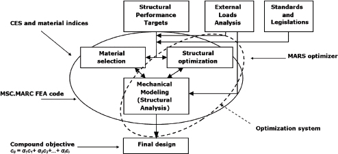
FIGURE 5-1 An approach to combining materials selection with structural optimization. SOURCE: N.S. Ermolzeva, K.G. Kaveline, and J.L. Spoormaker. 2002. “Materials Selection Combined with Optimal Structural Design: Concept and Some Results.” Materials and Design, Vol. 23, Issue 5, pp. 459-470.
contribute greatly to the lightweighting of military and civilian vehicles. An example is the work at Johns Hopkins University on topology optimization, a computational method for optimizing the design of structural systems as well as the design of multifunctional materials.13 Recent work at the University of Notre Dame has investigated structural topology optimization for blast mitigation in ground vehicles.14 These tools and techniques are being used in the private sector,15 but the technology is still a long way from being fully developed.
Accelerating the development of improved analytical tools for doing structural topology optimization would improve the speed and fidelity of the conceptual design phase. This research needs to be fully integrated into the overall systems-level analyses for efficient development of lightweighting solutions.
5.2.3 Design for Flexibility and Adaptability
Because the functional requirements placed on military vehicles may change over their service lives, adaptability and flexibility are important considerations when the vehicles are designed. However, designing for flexibility can lead to bloated systems as more features and capabilities are added. Indeed, in some sense, designing for flexibility is the antithesis of lightweighting. Additionally, flexibility often means compromising the performance goals for any one specific application. An example of this dilemma is the Joint Strike Fighter (F-35): it was designed to suit all of the services and, as a result, is heavier than originally desired.16
________________
13 See, for example, J.K. Guest and J.H. Prévost, 2006, “Optimizing Multifunctional Materials: Design of Microstructures for Maximized Stiffness and Fluid Permeability,” International Journal of Solids and Structures, Vol. 43, Issues 22-23, November, pp. 7028-7047; A. Asadpoure, M. Tootkaboni, and J.K. Guest, 2011, “Robust Topology Optimization of Structures with Uncertainties in Stiffness—Application to Truss Structures,” Computers & Structures, Vol. 89, Issues 11-12, June, pp. 1131-1141; and E. Lund, 2009, “Buckling Topology Optimization of Laminated Multi-material Composite Shell Structures,” Composite Structures, Vol. 91, Issue 2, November, pp. 158-167.
14 J.C. Goetz, H. Tan, J.E. Renaud, and A. Tovar. 2009. “Structural Topology Optimization for Blast Mitigation Using Hybrid Cellular Au tomata.” Proceedings of the 2009 Ground Vehicle Systems Engineering and Technology Symposium. August 28-20, Troy, Mich.
15 See, for example, “Study of Topography Optimization on Automotive Body Structure,” presentation by Rajan R. Chakravarty, General Motors, at the SAE World Congress & Exhibition, Detroit, Mich., April 2009.
16 In 2004, it became apparent that the STOVL (Short Take-Off Vertical Landing) variant of the Joint Strike Fighter was exceeding its weight targets to such an extent that it might be unable to accomplish its mission. A team was assembled to find ways to reduce its weight, which was done primarily by reducing its mission requirements. For example, an original design specification to carry two internal air-to-ground weapons in the 2000-pound class was changed to two weapons in the 1000-pound class, providing a 2000-pound weight reduction. See E.L.
A concept of flexibility embraced by the services is that of “multifunction structure plus,” wherein structural components perform additional functions. Examples include the Army’s use of structural batteries embedded within armor systems,17 the Navy’s advanced enclosed mast system (see Chapter 3), and the Air Force’s use of composites for both damage resistance and electromagnetic environment protection (see Chapter 2). Another area that aircraft manufacturers are considering involves lightning strike protection. Currently, because of the poor electrical conductivity of the polymer resins used in the composites, conducting metallic meshes must be added. Emerging technologies to embed carbon nanoparticles in the resin may raise the conductivities to the requisite levels and obviate the need for the mesh material in advanced composites. This could also yield additional benefits in the out-of-plane stiffness and strength.18
5.3 INSERTION OF LIGHTWEIGHTING MATERIALS AND TECHNOLOGIES
5.3.1 Timeline for Technology Development and Insertion
As discussed in Chapter 1, the time required to develop and certify materials generally exceeds that required for product development and certification. The time can range widely—from a few years for derivative materials on an expedited schedule to a decade or longer when a new class of material is under development or where new infrastructure is required to produce the material or structure.19 The major challenge is to shorten the timeline for materials development and bring it in line with that for product development.
This challenge is made more difficult by the mandates of the rigorous, gated20 approaches taken for development and certification of major engineering systems, which require that the maturity of new technologies be relatively high by the time critical system architecture decisions are made—typically when detailed design is initiated. New technologies that are not sufficiently mature at this stage are excluded from consideration unless backup configurations are carried along for risk mitigation. Unacceptably high levels of risk could be incurred if system architecture, design, or capability is critically dependent on a new technology, and failure to bring that technology to fruition results in significant design changes, compromises to system attributes, or delays in production.
Many companies and DoD agencies use the technology readiness level (TRL) assessment process, and the corresponding manufacturing readiness level (MRL) scale, for assessing and describing the maturity of materials and processing technology and the readiness of the corresponding manufacturing technologies and processes. The TRL scale and its definitions of maturity levels—originally proposed for use by NASA in the late 1980s and detailed in the Defense Acquisition Guidebook21—are summarized in Table 5-2. Definitions for the corresponding MRLs, which were developed and aligned with the TRL definitions somewhat later, are also shown. The TRL and corresponding MRL gate definitions are very consistent in scope and intent. In fact, through TRL-7 and MRL-7, the MRL gate exit criteria require that the corresponding TRL gate criteria be met as a condition of MRL gate completion.
When the TRL assessment approach is applied to materials and process development, the timeline and typical decision gates appear as illustrated in Figure 5-2. Two gates are often critical: TRL-3 (and MRL-3), where deci-
________________
Palmer, 2008, “F-35 Lightning II News: Weighing the F-35,” F-16.net, March 16, available at http://www.f-16.net/news_article2784.html. Last accessed May 26, 2011.
17AMPTIAC Quarterly, Vol. 8, No. 4, 2004.
18 See for example, (1) B. Wang, R. Liang, C. Zhang, P. Funches, and L. Kramer, 2003-2004, “Investigation of Lightning and EMI Shield ing Properties of SWNT Buckypaper Nanocomposite,” Final Report, May 1, 2003-October 31, 2004, available at http://handle.dtic.mil/100.2/ADA430333’; (2) T.W. Chou, L. Gao, E.T. Thostenson, Z. Zhang, and J-H Byun, 2010, “Review: An Assessment of the Science and Technol ogy of Carbon Nanotube-based Fibers and Composites,” Composites Science and Technology, Vol. 70, No.1, January, pp. 1-10; and (3) K. Kalaitzidou, H. Fukushima, and L. Drzal, 2010, “A Route for Polymer Nanocomposites with Engineered Electrical Conductivity and Percola tion Threshold,” Materials, Vol. 3, pp. 1089-1103, available at http://www.mdpi.com/1996-1944/3/2/1089.
19 NRC. 2004. Accelerating Technology Transition: Bridging the Valley of Death for Materials and Processes in Defense Systems. Washing ton, D.C.: The National Academies Press. Available at http://www.nap.edu/catalog.php?record_id=11108.
20 Gated technology developments programs specify criteria that must be met before a project can advance through a “gate” from one de velopment stage to the next.
21Defense Acquisition Guidebook, available at http://akss.dau.mil/dag/DoD5000.asp?view=document&rf=GuideBook\IG_c10.5.2.asp.
TABLE 5-2 Technology and Manufacturing Readiness Levels and Maturity Descriptions
| TRL or MRL Level | TRL Maturity Description | MRL Maturity Description |
| Pre-AcquisitionTechnologyDevelopment Phase | ||
| 1 | Basic principles observed and reported | Basic Manufacturing Implications Identified |
| 2 | Technology concept and/or application formulated | Manufacturing Concepts Identified |
| 3 | Analytical and experimental critical function and/or characteristic proof of concept | Manufacturing Proof of Concept Developed |
| 4 | Component and/or breadboard validation in laboratory environment | Capabilityto produce the technology in a laboratory environment |
| 5 | Component and/or breadboard validation in relevant environment | Capabilityto produce prototype components in a production relevant environment |
| 6 | System/subsystem model or prototype demonstration in a relevant environment | Capabilityto produce a prototype system or subsystem in a production relevant environment |
| Acquisition Phase | ||
| 7 | System prototype demonstration in an operational environment | Capabilityto produce systems, subsystems, or components in a production representative environment |
| 8 | Actualsystemcompleted and qualified through testand demonstration | Pilot line capability demonstrated; Ready to begin Low Rate Initial Production |
| 9 | Actualsystemproven through successful mission operations | Low rate production demonstrated; Capabilityin place to begin Full Rate Production |
| 10 | Not defined | Full Rate Production demonstrated and lean production practices in place |
SOURCE: Defense Acquisition Guidebook and DoD/MRL Manufacturing Readiness Level (MRL) Deskbook, version 2.0, May 2011.
sions to invest in comprehensive development and validation occur, and TRL-6 (and MRL-6), where materials, processes, and manufacturing readiness are considered sufficiently mature for use. This level of maturity is usually required for a technology to be included in the detailed design phase of a product or system.
For major DoD systems, development and acquisitions must adhere to Defense Acquisition Management System requirements. Three key milestones defined in this process relate to technology introduction. These milestones, illustrated in Figure 5-3, are defined by DoDI 5000.02:
- Milestone A: approval of entry into the Technology Development (TD) phase;
- Milestone B: approval of entry into the Engineering and Manufacturing Development (EMD) phase; and
- Milestone C: approval of entry into the Production and Deployment (P&D) phase.
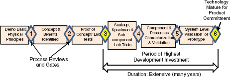
FIGURE 5-2 Typical technology readiness level (TRL) gates for development of materials and processes. The time period may vary widely, from around 2 years for derivative materials to >5 years for critical structural materials or when significant new materials systems or infrastructure are associated with the technology. Gate 3 is typically where significant investment and specific application focus begin. TRL-6 and MRL-6 are usually required prior to program initiation or product commitment. SOURCE: Adapted from B.A. Cowles and D. Backman, 2010, “Advancement and Implementation of Integrated Computational Materials Engineering (ICME) for Aerospace Applications,” a white paper sponsored by the Air Force Research Laboratory, AFRL-RX-WP-TP-2010-4151, March, available at http://www.dtic.mil/cgi-bin/GetTRDoc?Location=U2&doc=GetTRDoc.pdf&AD=ADA529049.
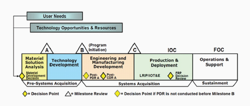
FIGURE 5-3 Defense acquisition system-level milestones. SOURCE: Department of Defense, Defense Acquistion Guidebook, Instruction 5000.02, December 8, 2008.
Perhaps the most important considerations regarding the relationship between technology readiness and these key system-level milestones are these:
- Technology and manufacturing maturity levels are required to be at TRL-6 and MRL-6, respectively, at or before Milestone B, when engineering and manufacturing development for the product or system begins.
- The Technology Development phase, which begins at Milestone A, must have sufficient scope, resources, and time to mature candidate technologies to TRL-6/MRL-6 before program initiation at Milestone B.
The implications of this requirement are significant. If the time, cost, or risk of maturing a new materials or processing technology prevents achievement of TRL-6, and/or MRL-6, by the time of program initiation at Milestone B, then it is likely that the technology will not be included in the system development. If it is included, some level of risk mitigation activity will be required. Risk mitigation activities may be significant depending on the impact the technology is expected to have on the system architecture, design, or capability.
The Technology Development phase is critical for both selection and maturation of technologies. This is especially true for lightweighting materials and related technologies, since—as described in this report—taking full advantage of lightweighting requires integration of such materials and technologies at the system level. This requires consideration of technologies and their potential impact well before Milestone B, and a commitment for their development and maturation before the detailed design phase and program initiation. An excellent discussion of the need for strategic selection of technologies, and this recurring issue of “bridging the valley of death” for technology insertion, can be found in the recent NRC report Evaluation of U.S. Air Force Preacquisition Technology Development22 (discussed in Chapter 1 of this report).
A generic representation of a gated product or system development process is shown in Figure 5-4. This expands the first part of the DoD graphic in Figure 5-3 slightly, in order to better illustrate the activities that occur from Milestone A (preacquisition technology development) into the acquisition phase where Milestones B and C occur.
The alignment of technology and manufacturing development with the product or systems development process is illustrated in Figure 5-5. Although the timelines for specific technologies and the programs themselves may vary widely, it is apparent that accelerating the materials and processes development cycle is critical. Technologies not already at TRL-3 (MRL-3) would likely have a difficult time being considered, even in the concept optimization phase. Moreover, higher levels of maturity would be expected or required before commitment of a materials technology to preliminary design activities. For technologies and design approaches with significant implications for system integration, such as materials and processes for lightweighting, benefits and impacts would best be assessed during the concept initiation phase—very early in the product development process, and early in the Technology Development phase of the Defense Acquisition process.
Ideally, technology development and product or system development would be interactive from inception of both phases. In such an ideal state, product concepts would influence technology (including materials) developments, beginning at the conceptual (and low- maturity) stage, and analysis of potential materials and their capabilities would be passed back to the concept initiation activities for product development. This loop would be iterated and refined to guide both product and materials/technology development—including the selection of appropriate technologies for investment. This is illustrated in Figure 5-6.
Then, again ideally, an accelerated materials and processes development and certification process would begin, in time to meet requisite maturity levels by the start of Program Initiation, corresponding to Milestone B and detailed design. Future materials and process technologies will require reductions in the time, cost, and risk of development and certification. Regardless of whether such an idealized process could be supported in practice, it is clear that accelerating the design, development, and insertion of new materials and manufacturing processes is critical to future products and systems. This is especially true for lightweighting materials technologies, which would be best selected and assessed as part of an integrated systems development process.
The next section discusses some approaches to better integrating the development of materials technologies with development of entire systems. The committee believes that ICME offers significant potential to enable improved materials design, accelerated development, and reduced risk for insertion. In addition, the capability to analytically describe materials in a manner compatible with processes for design and concept optimization will be essential to having these materials considered and integrated at the earliest stages of product development.
________________
22 NRC. 2011. Evaluation of U.S. Air Force Preacquisition Technology Development. Washington, D.C.: The National Academies Press. Available at http://www.nap.edu/catalog/13030.html.
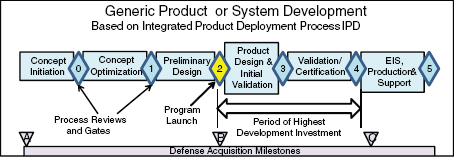
FIGURE 5-4 Generic gated product or system development process. Gate 2 is a key gate: it corresponds to defense acquisition process Milestone B, program initiation, where TRL-6 and MRL-6 maturity levels are required. The time to advance from gate 2 to gate 4 can vary widely: from perhaps 2 years for a derivative system to more than 10 years for a complex major system. SOURCE: Adapted from B.A. Cowles and D. Backman, 2010, “Advancement and Implementation of Integrated Computational Materials Engineering (ICME) for Aerospace Applications,” a white paper sponsored by the Air Force Research Laboratory, AFRL-RX-WP-TP-2010-4151, March, available at http://www.dtic.mil/cgi-bin/GetTRDoc?Location=U2&doc=GetTRDoc.pdf&AD=ADA529049.
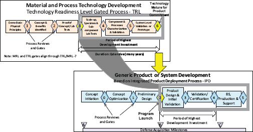
FIGURE 5-5 How technology readiness for materials and processes relates to product and system development. SOURCE: Adapted from B.A. Cowles and D. Backman, 2010, “Advancement and Implementation of Integrated Computational Materials Engineering (ICME) for Aerospace Applications,” a white paper sponsored by the Air Force Research Laboratory, AFRL-RX-WP-TP-2010-4151, March, available at http://www.dtic.mil/cgi-bin/GetTRDoc?Location=U2&doc=GetTRDoc.pdf&AD=ADA529049.
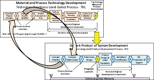
FIGURE 5-6 Ideal integration of early materials technology development and early systems development processes. SOURCE: Adapted from B.A. Cowles and D. Backman, 2010, “Advancement and Implementation of Integrated Computational Materials Engineering (ICME) for Aerospace Applications,” a white paper sponsored by the Air Force Research Laboratory, AFRL-RX-WP-TP-2010-4151, March, available at http://www.dtic.mil/cgi-bin/GetTRDoc?Location=U2&doc=GetTRDoc.pdf&AD=ADA529049.
5.3.2 Enabling Engineering Tools: (i) ICME
In the context of materials and process develoment, integrated computational materials engineering is the analog to systems engineering in vehicle design. For ICME, the “system” is the set of manufacturing processes, materials systems, and engineering applications.
The primary potential of ICME is more efficient and robust engineering of products, manufacturing processes, and materials.23 Improved efficiency can take the form of reduced development time, reduced certification time, or reduced development costs. ICME allows quantitative tradeoffs between material properties and manufacturing capabilities. It can lead to the development of new engineering products using existing materials, refinement of existing materials and manufacturing processes, or development of new materials and manufacturing processes. Two examples of successful ICME demonstrations are described in Boxes 5-2 and 5-3.
The example in Box 5-2 demonstrates the inherent advantage of computationally designed materials over empirically discovered materials in implementation of the accelerated insertion of materials (AIM) method, as the same tools and databases that are used to create the material also support the AIM models. These tools enable a “design for manufacturing” approach up front, eliminating scale up and streamlining qualification testing. ICME tools can be applied to the development of all vehicles, military and civilian. The use and further development of these tools for military purposes would be expected to benefit the development and improvement of commercial land, air, and maritime vehicles.
Figure 5-2-2 in Box 5-2 shows the iSIGHT-based Monte Carlo simulation of property variation in manufacturing (blue line), which used data from only three production-scale heats to accurately forecast 1 percent minimum
________________
23 NRC. 2008. Integrated Computational Materials Engineering: A Transformational Discipline for Improved Competitiveness and National Security. Washington, D.C.: The National Academies Press. Available at http://www.nap.edu/catalog.php?record_id=12199.
design allowables. The model was validated by 10 production scale heats (“experimental data”) where the final designed 1 percent allowable ultimate tensile strength (UTS) was within 1 ksi of the data (inside the red ellipse). This approach employed the linear-transformation sparse data fusion strategy first demonstrated for aeroturbine superalloys during DARPA-AIM. The forecast allowed fine-tuning of process optimization at an early stage, eliminating re-testing costs in the qualification cycle.24
5.3.3 Enabling Engineering Tools: (ii) Physics-Based Models of Material Behavior
Future military technologies will place increasing demands on materials in extreme service environments— notably, under high levels of stress, strain, strain rate, temperature, and heat flux. Tremendous progress has been made over the past two decades in the development of finite element codes for thermostructural analysis. Significant advances have also been made in the development of continuum-level constitutive laws for inelastic deformation, damage evolution, and rupture. Together, the finite element codes and the constitutive laws have proven effective in analyzing structural response over a wide range of loading conditions. Notwithstanding this progress, there remain large gaps in the understanding of the underlying physical processes that operate in complex multiphase systems, especially at very high strain rates and in the shock domain. New information-rich experiments and corresponding material models are needed. Specific areas that require attention include:
- The linkage of strength, damage evolution, and fracture to material chemistry, processing history, and microstructure;
- Techniques to bridge time and length scales in material models; and
- New numerical techniques to model the pertinent physical processes with high fidelity and exploit the computational power now available to the DoD.
The U.S. Department of Energy has sponsored extensive work in physics-based modeling and simulation at its national laboratories, much of it to support the Nuclear Test Ban treaty (i.e., to provide assessments of material and structural behavior for nuclear weapons in the absence of testing). The fundamental physics codes developed for this purpose are relevant for all materials design efforts. For example, work at Sandia National Laboratories has resulted in open-source tools for molecular modeling that has been used extensively and is continuously updated to add more fundamental physics information and to increase computational speed. Continued progress on such physics-based modeling and simulation is needed.25
Example of Modeling Challenges: Polymer Composites
An example of the progress and the disconnects in current modeling abilities for materials relevant to structural lightweighting is in the area of polymer composite materials. Composites consist of a polymer resin material of specific chemical structure, a fiber reinforcement, a surface modification of the fibers, and a defined geometric arrangement of the fibers within the matrix. Recently, nanoparticles have been added to the resin and/or the fiber/matrix interfaces, where the nanoparticles themselves typically possess a surface chemical functionalization to make them compatible with the matrix material. These composites are constructed through a variety of processing methods, during each of which variations in temperature, pressure, and other processing conditions significantly affect the final composition and properties of the composite material. Current chemistry models can address changes in the viscosity of resins due to alterations in the polymer backbone chemistry and molecular weight, and processing models can predict the flow of polymer through a fiber mesh to guide infiltration. In addition, macro-level relationship metrics between resin chemistry and toughness of resin have been developed. To tune stiffness and
________________
24 CJ. Kuehmann and G.B. Olson. 2009. “Computational Materials Design and Engineering.” Materials Science and Technology, Vol. 25, Issue 4, pp. 472-478. Available at http://www.mendeley.com/research/computational-materials-design-engineering/.
25 A survey of computational models for failure, damage, and degradation in composite materials can be found in Appendix E of NRC, 2005, Going to Extremes: Meeting the Emerging Demand for Durable Polymer Matrix Composites, Washington, D.C.: The National Academies Press, available at http://www.nap.edu/catalog.php?record_id=11424.
Box 5-2
ICME Example: Flying Cybersteel
An important milestone in ICME technology has been the streamlined flight qualification of the Ferrium S53 aircraft landing gear steel, the first fully computationally designed and qualified material. Using the multiscale systems approach represented by Figure 5-2-1, computational tools were used to apply predictive science to each of the process/structure, structure/property, and property/performance links indicated by connecting lines. Computational multicomponent thermodynamics1 were used to combine materials science, applied mechanics, and quantum physics for parametric design integration.
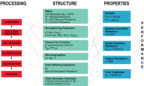
FIGURE 5-2-1 System chart representing Ferrium S53 landing-gear steel. SOURCE: G.B.Olson. 2011. "Computational Materials Design: Making CyberSteel Fly.” Northwestern University & QuesTek Innovations LLC. Evanston, III. April 6. Available at http://www.transportation.northwestern.edu/docs/2011/2011.04.06.BAC_Olson_Presentation.pdf. By permission from QuesTek Innovations LLC.
The computationally designed material, developed by QuesTek Innovations, achieved a high combination of strength, toughness, and resistance to both corrosion and stress corrosion. Actual design was achieved in 2 years using only five design prototype alloys, in contrast to the hundreds of alloys required for the traditional empirical development process. In terms of its specific properties meeting critical weight constraints, the Ferrium S53 alloy performs as well as advanced titanium alloys at a small fraction of the material and manufacturing cost.
The alloy was the first demonstration of the DARPA-AIM method in the flight qualification of a new material (see the description of the AIM initiative in Chapter 1). Using the iSIGHT process integration and design optimization software, sensitivity analysis was performed at the earliest stage of parametric design to minimize the propensity for property variation. At the same time, a “design-for-scale” approach constrained alloy composition
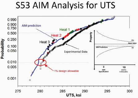
FIGURE 5-2-2 Forecast and measured cumulative distribution of ultimate tensile strength (UTS) for Ferrium S53. Inset represents the goal of forecasting variation validated at the 10 heat level of MMPDS specification from data on 3 heat level of AMS specification. SOURCE: G.B. Olson. 2011. "Computational Materials Design: Making CyberSteel Fly.” Northwestern University & QuesTek Innovations LLC. Evanston, III. April 6. Available at http://www.transportation.northwestern.edu/docs/2011/2011.04.06.BAC_Olson_Presentation.pdf. By permission from QuesTek Innovations LLC.
during all stages of development to the processability conditions viable at the largest required scale of ingot production. The approach successfully demonstrated the complete elimination of the scaleup component of alloy development—each scale ingot (from 3 lb to 15,000 lb) was produced with the required microstructure and properties the first time, without the usual multiple iterations to find a processable composition at each scale.
Figure 5-2-2 illustrates the simulation. Design of this alloy went from a clean sheet of paper to flight qualification in just 8.5 years. The developers stated that this could have been accomplished in 5 years if support had been continuous. The project's sponsor estimated a cost savings of $50 million relative to traditional empirical development of the Strategic Environmental Research and Development Program.2
________________
1G.B. Olson, 1997. “Computational Design of Hierarchically Structured Materials,” Science, Vol. 277, No. 5330, pp. 1237-1242. See also C.J. Kuehmann and G.B. Olson. 2009. “Computational Materials Design and Engineering,” Materials Science & Technology, Vol. 25, No. 4.
2DoD-EPA-DOE. 2003. Strategic Environmental Research and Development Program (SERDP) Bulletin, Winter, No. 15, p. 6.
Box 5-3
ICME Example: Development of Superalloy GTD262 at GE
GE was one of the three companies that carried out a DARPA-AIM project, which facilitated the adoption of the AIM/ICME approach inside the company. During the AIM project, extensive testing was performed on the reliability of thermodynamic databases in predicting phase stability in multicomponent superalloys,1 which resulted in a rigorous assessment of the fidelity level of thermodynamic data for several key phases.
A GE-funded project was initiated in 2002 and executed by both GE Global Research and GE Energy to replace tantalum (Ta), a critical refractory element subjected to high risks of supply and price disruptions, in superalloy GTD222, which was widely used in nozzles and vanes in GE power generation gas turbines. Using the AIM/ICME approach, especially by integrating computational thermodynamic predictions of phase equilibria with GE’s materials property models and databases, Jiang and his collaborators designed four alloys with niobium (Nb) replacing Ta and with modifications to the concentrations of other elements to optimize and balance key properties and producibility2 Laboratory-scale tests were performed on those four Ta-free alloys for mechanical properties, oxidation resistance, weldability, and castability The best of the four alloys doubled creep-resistance performance; other properties remained comparable to those of the Ta-bearing GTD222. It was subsequently subjected to an industrial-scale production trial (Figure 5-3-1) and successfully passed the qualifications without any technical hurdles. The new alloy was named GTD262; it was successfully introduced into GE power generation gas turbines starting in 2006, and it is experiencing much wider adoption today.
The first key lesson learned from this project is that reliable thermodynamic databases are essential to the design of multicomponent alloys and that fidelity tests are required to increase the confidence level for the predictions in specific regions of compositions. High-confidence thermodynamic predictions not only eliminated several of the experimental iterations that are usually needed to obtain the right alloy compositions (GTD262 was designed without even a second round of experimental trials), but also eliminated the long-term thermal exposure experiments that are generally required to test the propensity to form detrimental phases. GTD262 was developed and introduced in about 4 years from concept to industrial production (including design property data gathering) at less than 20 percent of the typical alloy development cost, which is very likely a record in both speed and cost in insertion of a new alloy into a gas turbine.
The second key lesson is that integration of thermodynamic predictions with property predictions from physics-based models and regression-based property databases is vital to the balance of properties. GE’s proprietary models and internal databases played an important role in the development of GTD262. More widely applicable, physics-based, but experimentally validated microstructure and property models as well as higher-fidelity databases (especially thermodynamic databases with higher accuracy and wider compositional validity) are badly needed for the development of new alloys whose compositions differ vastly from those of existing alloys.
Early engagement with production/application teams at GE Energy in terms of multiple design goals and manufacturability has contributed significantly to the rapid and smooth transition from laboratory to production, which was another important lesson learned from the prior DARPA-AIM project. The rapid development of GTD262 is the first successful landmark that has helped establish within GE the credibility of computational
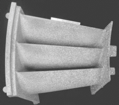
FIGURE 5-3-1 A production trial gas turbine nozzle made up of a new superalloy, GTD262. SOURCE: Courtesy of the General Electric (GE) Company.
alloy design and its associated methodologies, models, and databases. GE teams have since successfully designed and deployed into GE products new superalloys at similar high speed and low cost as a result of using the same AIM/ICME approach, which has now firmly established a vital role in new alloy development at GE.
________________
1 J.-C. Zhao and M.F. Henry. 2002. “CALPHAD—Is It Ready for Superalloy Design?” Advanced Engineering Materials, Vol. 4, No. 7, pp. 501-508.
2L. Jiang, J.-C. Zhao, and G. Feng, 2005, “Nickel-Containing Alloys, Method of Manufacture Thereof,” and articles derived therefrom, World Patent Application WO2005056852, filed on September 29, 2004, published on June 23, 2005; U.S. Patent Application 20100135847, filed on October 21, 2009, published on June 3, 2010.
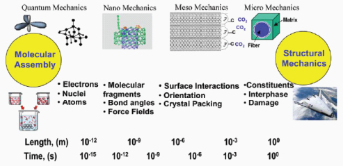
FIGURE 5-7 Schematic illustration of relationships between time and length scales for the multiscale simulation methodology. SOURCE: Adapted from T.S. Gates, G.M. Odegard, S.J.V. Frankland, and T.C. Clancy, 2005, “Computational Materials: Multi-scale Modeling and Simulation of Nanostructured Materials,” Composites Science and Technology, Vol. 65, pp. 2416-2434.
strength of the composites, micromechanics and three-dimensional failure models are used, based on additional data from coupon-level testing. The models can be used to tune toughness qualitatively based on resin chemistry, but they are not yet quantitatively predictive (see Chapter 3 for additional details). The length scales over which modeling is required are illustrated in Figure 5-7.
A significant gap arises between molecular-level modeling and the modeling of final structural properties of the composite based on continuum assumptions. A major difficulty arises in the prediction of the local properties of the polymer near the fiber and nanoparticle interfaces as a function of resin chemistry and processing conditions. (Complexities of the modeling challenges are illustrated in Figure 5-8.) Another difficulty is that even the relative dispersion of nanoparticles within a resin/composites cannot be predicted as a function of particle type, size, and processing. Yet, since these composites are systems of interfaces with nearly all polymer existing in the neighborhood of interacting surfaces (fiber and/or nanoparticle), these local polymer properties are critical. Therefore, traditional composite modeling theories based on fiber layup must use coupon-level properties from unidirectional specimens in order to build up properties of the composites. Finally, although prediction of stiffness of composites based on traditional continuum and micromechanics modeling theories is well developed, predictions of more challenging properties, such as strength, toughness, and ballistic performance, need significant attention. Thus, while progress is being made, the existing gaps in modeling preclude the goal of being able to predict a composite system’s properties based purely on knowledge of the individual constituents and the processing history. Significant progress in implementing composites as tailored lightweight solutions in a wide variety of structural applications will require the ability to design the material composition and processing to obtain desired properties.
5.4 TRANSITION OF LIGHTWEIGHTING TECHNOLOGIES INTO FIELDED SYSTEMS
Introduction of new technologies into complex systems typically requires significant experimental testing from the level of materials to coupons to components to subsystems. While modeling can accelerate this process, ultimately the new technology must be tested in field conditions as part of a complete system. Because lightweight materials are often considered a risk in terms of strength and fatigue life, many new technologies are first
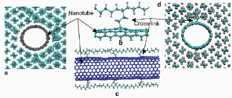
FIGURE 5-8 Representative volume element for modeling a nanotube-reinforced composite of polyethylene. SOURCE: T.S. Gates, G.M. Odegard, S.J.V. Frankland, and T.C. Clancy, 2005, “Computational Materials: Multi-scale Modeling and Simulation of Nanostructured Materials,” Composites Science and Technology, Vol. 65, pp. 2416-2434.
incorporated into legacy platforms in non-critical, secondary components. For example, as discussed in Chapter 2, polymer composites were incorporated in aircraft air intake components before being used in primary structures such as wings and fuselage. In other cases such as lightweight ballistic and blast protection for ground vehicles, new ceramic and composite plates were simply bolted or adhered onto existing doors and undercarriages in place of steel. Designing systems to facilitate selection from many component options, depending on function and availability (e.g., the “A+B” approach described in Chapter 1), can speed up the adoption of new technologies.
For much greater leaps in system capability, however, the use of advanced technology demonstrations26 can bring together interdisciplinary teams that strive for revolutionary advances (see Chapter 1 and Box 5-2). ATDs can be characterized as relatively large scale both in resources and complexity and as enabling enhanced military operational capability, operator/user involvement from planning to final documentation, testing in a real and/or synthetic operational environment, a finite schedule (e.g., 3-4 years), and the need to meet mutually agreed upon cost, schedule, and objective performance baselines such that there is a rapid transition to deployment.
The recent revision to the Defense Acquisition Guide, through DOD Instruction 5000.02, actually calls for ATDs in the preacquisition phase of development—that is, before Milestone B, in the technology development phase. This would seem to be a good opportunity to integrate ICME methods to accelerate design and development of prototypes for ATDs, especially for lightweighting materials and their integration with structural requirements and design configurations.
ATDs offer an important opportunity to use system engineering and design optimization and it would be wise to take maximum advantage of this opportunity. To ensure that this is done, ATDs should use a gated approach to development that includes all of the requirements that an actual, fielded system would have to meet. Although, because it is an ATD, not all of these requirements would need to be validated by test, there should be clear direction as to how the requirement would be met in a production vehicle. Additionally, where feasible, ICME tools can be used in ATDs to accelerate the early stages of design and optimization and to improve the robustness of the final hardware.
ATDs have potential to be very good vehicles for evaluation of lightweighting concepts, especially integrated materials and configuration concepts. ICME investment, especially related to lightweighting materials technolo-
________________
26 Note that ATDs are but one process for facilitating the transition from technology development to deployment. For others, see (for example) the list at http://www.onr.navy.mil/en/Science-Technology/Directorates/Transition/Technology-Transition-Initiatives-03TTX.aspx. Some of these other initiatives may also provide opportunities to develop and transition lightweighting materials and designs.
gies, would facilitate success through accelerated assessment and analytical prediction of new material behavior. This would enable an ATD (or prototype) to be designed and manufactured with reduced risk and on an accelerated schedule.
As noted in Chapter 4 in the discussion of the JLTV competitive prototyping program, and of virtual prototyping, such a step—to try out new materials and new designs for lightweighting in terms of their effects on other attributes—could be considered in the “pre-ATD” or “pre-prototyping” stage. The design solutions that look the most favorable could then progress to the ATD stage or physical prototyping stage.
ATDs have brought about revolutionary military vehicles. For example, UAVs, advanced ship configurations, and lightweight vehicles are technologies that emerged from ATD projects begun in the 1990s. But not every ATD has proven to be a resounding success. Lightweight transport vehicles for the Army proved to be vulnerable to IEDs and assault weapons because of inadequate armor,27 and UAVs suffered from poor ground station interfaces and required inordinate maintenance. Some of the problems encountered with these vehicles can be attributed in part to their hasty introduction into service, despite their having been intended as demonstration vehicles only. Evidently the protocols used to “graduate” ATDs from demonstrators to fielded systems proved inadequate.28 An excellent set of recommendations for bridging the gap between ATDs and fielded systems is detailed in a previous NRC report.29
5.5 MANUFACTURING AND MAINTENANCE TECHNOLOGIES
THAT FACILITATE LIGHTWEIGHTING
Despite the fact that the United States has been the innovator of virtually all major manufacturing technologies for defense products in the post–World War II era, there is widespread realization that the competitiveness of the U.S. manufacturing industry has declined over the last 20 years. One consequence is that the U.S. defense industry has had to rely more on global manufacturers for supply of raw materials, intermediate goods, and many niche products.30
The ability of the DoD to “lightweight” will be dependent to some extent on the preservation and nurturing of the domestic manufacturing base. It would also benefit significantly from a parallel commercial base for air, sea, and land transport systems. Parallel markets would have the effect of reducing risk across all stages of technology and manufacturing readiness and reducing associated costs. This trend has indeed been observed historically, wherein the “knowledge spillovers” from the commercial sector have resulted in military systems with longer service lifetimes.
While advances have been made in reducing raw material cost through DoD efforts (e.g., the Title III Program on National Defense Industrial Resources Preparedness), the secondary processing methods for many newer material candidates or product forms have not matured and are relatively undeveloped compared with those for steel (e.g., see Table 5-3). For example, robust manufacturing processes for fabricating complex structural components from continuous-fiber-reinforced composites have not yet achieved the rates and consistency of steel stamping.
Titanium is also recognized as a leading candidate material for lightweighting, but its viability for broad use is questionable because of high acquisition costs and risks associated with its availability. Since no single military application will raise demand for such materials to support and sustain production levels, there is a need to leverage demand with the commercial industry.
It is important to note that investments in fundamental research that leads to exciting new materials typically
________________
27 Dick Engwall, “First Army ACAT-1 Program TRL Review Including MRL Critique,” briefing to NDIA Manufacturing Commmittee Meet ing, November 2008. This briefing includes some excellent suggestions on how to change the current paradigm.
28 Stew Magnuson. 2010. “New Truck to Show the Way for Acquisition Reforms.” National Defense Magazine. August. Available at http://www.nationaldefensemagazine.org/archive/2010/August/Pages/NewTruckToShowTheWayforAcquisitionReforms.aspx.
29 NRC. 2003. Use of Lightweight Materials in 21st Century Army Trucks. Washington, D.C.: The National Academies Press. Available at http://www.nap.edu/catalog.php?record_id=10662.
30 See, for example, RAND Corporation, 2004, “High Technology Manufacturing and US Competitiveness,” March 20, papers at http://www.innovationpolicy.org/consolidating-the-multitude-of-reports-callin; and NRC, 1999, Defense Manufacturing in 2010 and Beyond, Washington, D.C.: National Academy Press, pp. 12-15.
do not translate to commercial products or military application for many decades because the R&D on the scalable processing of the material into functional forms follows at a much later stage. Accelerated use of new materials requires parallel investments in manufacturing process R&D.
A critical need in the overall readiness of fielded combat systems is the “determination of remaining usable life and the quantitative prediction (i.e., prognosis) of future operating capability.” This would mitigate the “fear of failure” in the war theater and give commanders the “ability to adaptively manage and deploy combat systems that might otherwise be removed from service.”31 In simple cost terms, extending the service life of a component with a conservative 6-year life by 2 years reduces the cost of that component by 25 percent. There are also significant operational benefits. A good example of this is the (now-canceled) Future Combat System (FCS) program.32 Here the requirements for reliability and operational availability were to be met by employing a prognostics-based approach to maintenance, allowing decisions to be made to replace critical parts vulnerable to failure just before they fail or before an upcoming mission. Such condition-based maintenance (CBM) approaches are becoming more widespread within U.S. industry and the U.S. military.
“A complete CBM system requires the integration of a variety of hardware and software components,”33 as demonstrated by an ongoing project titled “Light Amphibious Vehicles—Sense and Respond Logistics Phase I, II, III, IV,” organized by the National Center for Manufacturing Sciences under its Commercial Technologies for Maintenance Activities.34 The platform itself, with monitoring and communications equipment onboard, senses vehicle health information and alerts the crew to vehicle status. The data are shared wirelessly with operations in the immediate vicinity. Remote technicians can then provide real-time guidance to on-site personnel about maintenance decisions.
The initial phases of this project have demonstrated that early warning has reduced maintenance cycle time by approximately 50 percent and increased fleet-wide operational availability by 7 percent. Maintenance cost avoidance exceeded $22 per mile based on overall preventive maintenance monitoring, and the vehicles are expected to see an overall 14 percent increase in mean time between failure. These improvements should continue to increase as further testing and optimization proceed.
5.6 AVAILABILITY OF LIGHTWEIGHTING MATERIALS
As noted in Chapter 1, two cornerstones of lightweighting are (1) low- or reduced-density, high-specific-performance35 alloys, and (2) fiber-reinforced composite materials. A summary of the most important of these materials and their current status is provided in Table 5-3, which also includes high-strength steels, because even modest improvements in steel strength can have a large impact due to the large amounts of steel used in military vehicles. Some alloys, such as those based on aluminum, are readily available. They are used widely in industry in sufficiently large volumes to support the operations of multiple suppliers.
Magnesium is a structural metal used only in low volumes because conventional processing of magnesium sheet is expensive and limited in availability and industrial capacity. Magnesium alloys, and components based on wrought magnesium, have not found widespread commercial or military use. Consequently, neither the United States nor Europe currently has adequate capabilities for producing these alloys or manufacturing magnesium components on a large scale. Domestic production capabilities that had previously been established have been
________________
31 This section is drawn from information at http://www.acq.osd.mil/log/mpp/cbm+_related_links.html.
32 The Future Combat Systems program was the Army’s principal modernization program. U.S. Defense Secretary Robert Gates announced in April 2009 that he was killing the vehicle portion of the Army’s $160 billion Future Combat Systems. FCS was originally envisioned as “a program that would create a group of brand-new super-brigades and outfit them with next-generation, hyper-connected vehicles and gear.” See Kris Osborn, 2009, “FCS Is Dead; Programs Live On: U.S. Army to Dissolve Flagship Acquisition Effort,” Defense News, May 18, available at http://www.defensenews.com/story.php?i=4094484.
33 See http://www.acq.osd.mil/log/mpp/cbm+_related_links.html.
34 “CTMA is a collaboration between the National Center for Manufacturing Sciences (NCMS), its member companies, and the DoD. Under a historic Cooperative Agreement between NMCS and OSD (L&MR) MPPR, NMCS and its member companies co-sponsor technol ogy development, deployment, and verification with DoD organic maintenance activities.” Excerpted from http://www.acq.osd.mil/log/mpp/cbm+_related_links.html. See that website for more information.
35 Specific performance (e.g., strength) is performance divided by density.
TABLE 5-3 Current Status of Lightweight-Enabling Structural Materials
| Material | Applications | Material Availability | Manufacturing Capability |
Cost |
| Magnesium |
Thick sections for |
Limited domestic |
Manufacturing |
High compared with |
| Titanium |
Structures, armor, |
Adequate |
Inability to join thick |
Very high compared with |
| Organic matrix composites |
Ship superstructures Airframes and aero-engines Land vehicle structure Peripherals |
Some limitation on |
Limited domestic |
Competitive |
| Ceramic matrix composites |
Aircraft engines High-temperature structures |
Very limited domestic |
Limited sources |
Extremely high |
| Metal matrix composites: (a) Fiber reinforced |
Aircraft, engine structure Ship superstructure |
Limited sources for |
Very limited sources |
Very high compared with |
| Metal matrix composites: (b) Particulate reinforced |
Land vehicle structure, |
Limited sources for |
Limited sources and |
High compared with |
| Laminated ceramic structures |
Transparent armor |
Extremely limited |
Laboratory-level |
Extremely high |
| High-strength steels |
Lightweight |
High |
High |
Low |
discontinued or the companies have gone out of business. This contraction in capability is due in large part to the excess production of magnesium in China and Russia during the 1980s and 1990s, the “dumping” of excess magnesium into U.S. markets, and the resulting global price reductions.36
Nevertheless, there have been some encouraging developments recently in processing for improvements in strength and toughness, making these materials even more competitive with aluminum and steel. For example, Nanomag TTMP—a processing innovation that is eco-friendly and produces ultra-fine-grain magnesium sheet— has led to significant improvements in strength and toughness, making these materials even more competitive with aluminum and steel.37 In addition, there have been developments in equal channel angular processing that
________________
36 G.J. Simandl, M. Irvine, and J. Simandl. 2007. “Primary Magnesium Industry at a Crossroads?” Light Metal Age, April, pp. 32-35.
37 Nanomag TTMP is a new technology developed by Thixomat, Inc., and the University of Michigan for injection molding of magnesium sheet forms. See J. Huang, T. Arbel, L. Ligeski, J McCaffrey, S. Kulkarni, J. Jones, T. Pollock, R. Decker, and S. LeBeau, 2010, in Magnesium Technology, Warrendale, Pa: TMS; and R. Decker, J. Huang, S. Kukarni, and J. Jones, 2010, in Materials Science Forum, Vol. 654-656, pp. 574-579.
have demonstrated dramatic improvements in ductility.38 Also, some new alloys have been developed that have very high strengths.39
Titanium alloys have long been used in aircraft and propulsion structures. They exhibit superior specific strength and elevated temperature capability relative to steels, without compromising specific stiffness. Titanium alloys are readily formable into sheet and bar forms and can be forged at elevated temperatures. However, for aerospace grades, the cost of titanium alloy is typically several times that of steel or aluminum alloys. A 2001 assessment revealed, “Just accounting for the extraction and processing costs to produce ingot, titanium is ~30 times more expensive per pound than steel and ~6 times that of aluminum. The cost gap for titanium widens when fabricating components and structures.” 40 The extensive use of titanium in aerospace vehicles is testament to the cost premium on lightweighting that the industry can bear. Although significant weight benefits could be achieved through the use of titanium alloys in land vehicles and ships, their high cost and a somewhat limited production capability severely restrict their use in these areas.
Carbon fibers have been used extensively as reinforcements in polymer matrix composites. These fibers have been central to the development of composite airframes for the Boeing 787 and Airbus 380 aircraft. Nonetheless, there are now fewer suppliers of carbon fiber than there were a decade ago. In addition, there are few fiber manufacturers today making the high-modulus and ultra-high-modulus fibers that will likely be in greatest demand in future DoD programs. Furthermore, there is not much spare fiber production capacity. The latter deficiency was made clear, for instance, in the worldwide shortage of carbon fiber that followed large-scale efforts in Japan to seismically retrofit all bridge and elevated roadway supports with wound carbon fiber braces,41 following the Hyogoken-Nambu earthquake in 1995. The availability and sourcing of high-performance carbon fibers has been a long-term concern for the DoD; the National Defense Authorization Act has, on two occasions (2001 and 2005), directed the Secretary of Defense to prepare an assessment for the Committees on Armed Services of both the House and the Senate.42
The limited availability of high-temperature silicon carbide fibers presents a more dire problem. These are being investigated primarily as reinforcements in ceramic matrix composites for aircraft engines and future high-performance military applications such as rocket nozzles and scramjets. The available volume of these composites is currently small, and there is no large-scale manufacturer of these fibers outside Japan. The maximum temperature capabilities of these silicon carbide fibers are also limited (to about 1300-1400°C, depending on service life). Continued and sustained development of new fibers will be necessary to reach the targeted temperature capabilities (above 1500°C).
Polycrystalline oxide fibers, based on sol-gel derived alumina and mullite, have been developed by 3M Company under joint funding with DARPA for use in high-temperature ceramic composites. Although the temperature capabilities (1100-1200°C) of current state-of-the-art oxide fibers are well below the target, these fibers have found commercial application as reinforcements for aluminum alloy cables for power transmission, displacing steel-core, aluminum-braided power cables.
The availability of polymer-based fibers used in armor, such as Kevlar, is of less concern. Kevlar is very widely used in a variety of commercial applications that do not depend on DoD support. Furthermore, the manufacturer (DuPont) is an exceptionally large, domestic company. Another fiber—based on highly oriented, high-molecular-weight polyethylene and sold under the trade names Dyneema (DSM) and Spectra (Honeywell)—exhibits very low density (less than 1 g/cm3) and exceptional strain-to-failure, or percent elongation before breaking (2.9 to 3.5
________________
38 W. Kim, C. An, Y. Kim, and S. Hong, 2002, Scripta Materialia, Vol. 47, pp. 39-44; Y. Yoshida, K. Arai, S. Itoh, S. Kamado, and Y. Kojima, 2005, Science and Technology of Advanced Materials, Vol. 6, pp. 185-194; and T. Mukai, M. Yamanoi, H. Watanabe, and K. Higashi, 2001, Scripta Materialia, Vol. 45, pp. 89-94.
39 K.Y. Zheng, J. Dong, X.Q. Zeng, and W.J. Ding, 2008, Materials Science and Engineering A, Vol. 489, p. 103; B. Smola, I. Stulíkova, F. von Buch, and B.L. Mordike, 2002, Materials Science and Engineering A, Vol. 324, p. 113; and S.M. He, X.Q. Zeng, L.M. Peng, X. Gao, J.F. Nie, and W.J. Ding, 2007, Journal of Alloys and Compounds, Vol. 427, p. 316.
40 B. Hurless and F.S. Froes. 2002. “Lowering the Cost of Titanium.” AMPTIAC Quarterly, Vol. 6, No. 2. Available at http://ammtiac.alion-science.com/pdf/AMPQ6_2ART01.pdf. Last accessed June 21, 2011.
41 T. Ogaata and K. Osada. 2000. “Seismic Retrofitting of Express Bridges in Japan.” Cement and Concrete Composites, Vol. 22, pp. 17-27.
42 “Polyacrylonitrile (PAN) Carbon Fibers Industrial Capability Assessment, OUSD (AT&L) Industrial Policy,” October 2005. Available at http://www.acq.osd.mil/ip/docs/pan_carbon_fiber_report_to_congress_10-2005.pdf.
percent).43,44,45 This fiber shows considerable promise for composites in armor systems. Yet the full potential of these fibers has yet to be realized in commercial products. Theoretical considerations and laboratory-scale demonstrations indicate that strength elevations of more than 50 percent could be achieved in the next generation of commercial fibers. This goal will require a robust research effort and sustained resources to bring it to fruition. See Section 5.3.3 for an example of the challenges involved in modeling the behavior of polymer composite materials.
Finally, although high-strength steels may not immediately be recognized as materials for lightweighting, the design of new steel compositions with even modest strength improvements (10 to 20 percent), combined with design optimization and manufacturing innovations, can have significant impact in creating lighter structures. The benefits are derived in part because of the large use of steels in military vehicles. However, the lack of availability of new steels and of large-scale production remains an impediment to their wider use in military vehicles and components.
5.6.1 Design Expertise in the Process Industry Sectors
From 1998 to 2008, the U.S. Department of Energy’s Office of Industrial Technologies (renamed the Industrial Technologies Program, ITP) partnered with trade organizations representing the nine energy-intensive industries on which the branch has focused its R&D portfolio in order to identify common needs, concerns, and visions for long-term investment and partnering:46 Elaborate roadmaps for new technology development were created with each of the nine industry groups, of which the five groups relevant for the current NRC lightweighting study are aluminum, glass, steel, metal casting, and chemicals. These roadmaps identified near-, mid-, and long-term R&D priorities, performance targets, and programs to advance the state of these “industries of the future” with the aim of strengthening U.S. capabilities and efficiencies in the supply of these base materials to domestic manufacturers.
Each roadmap generated grand challenges that have resulted in numerous internal R&D and cross-industry collaborations involving leading material suppliers, which in turn generated a great deal of material and design knowledge that is in the private and public domains. The respective trade associations—e.g., the Aluminum Association, Steel Industry Market Development Institute, Glass Manufacturers Association, and American Chemical Society—have archived and disseminated much of the information through project reports. Such vital information can be drawn upon by military manufacturers to initiate new R&D in design, manufacturing, and demonstration of system-level lightweighting solutions. Examples of high-priority material and processing research include:47
- Computer design tools;
- High-temperature materials, including refractories;
- Casting, advanced forming, and tool and die materials;
- Databases and process modeling;
- Joining and welding;
- Coating properties, processing, and applications;
- Mold and die filling;
- Ceramic and composite reliability and performance data;
- Erosion- and corrosion-resistant materials and coatings;
- Materials for sensors; and
- Separation methods, recycling, waste, and by-product treatment.
________________
43 Keith McDaniels, R.J. Downs, Heiner Meldner, Cameron Beach, and Chris Adams. 2009. “High Strength-to-Weight Ratio Non-Woven Technical Fabrics for Aerospace Applications.” Cubic Tech Corporation, Mesa, Ariz. Available at http://www.cubictechnology.com/Technical%20Fabrics%20for%20Aerospace%20Applications.pdf.
44 “A Constitutive Model for DYNEEMA UD Composites,” available at http://www.iccm-central.org/Proceedings/ICCM17proceedings/Themes/Materials/HIGH%20PERFORMANCE%20FIBRES/D6.9%20Iannucci.pdf. Accessed October 21, 2011.
45 Honeywell Spectra Fiber 1000 Product Information Sheet. Available at http://www51.honeywell.com/sm/afc/common/documents/PP_AFC_Honeywell_spectra_fiber_1000_Product_information_sheet.pdf.
46 DOE-EERE, OIT, 2000, Program Plan for Fiscal Years 2000 Through 2004, Industrial Materials of the Future, July; NRC, 2000, Materials Technologies for the Process Industries of the Future: Management Strategies & Research Opportunities, Washington, D.C.: National Academy Press.
47 Richard Silberglitt and Jonathan Mitchell. 2001. Industrial Materials of the Future (IMF) R&D Priorities. Rand Corporation study for NREL.
Despite the seemingly disparate considerations in lightweighting of the full spectrum of military vehicles, important commonalties are evident. Future policies and investment strategies that are founded in these commonalties should yield the greatest impact on lightweighting of future military vehicles.
Furthermore, with the enormous magnitude of military operations and associated costs, such strategies are expected to have a broad impact on national concerns that extend beyond the military: notably, the sustainability of fossil fuel use at present levels, the balance of trade, and domestic employment opportunities.


