
Lightweighting Maritime Vehicles
3.1 CURRENT STATE OF LIGHTWEIGHTING IMPLEMENTATION AND METRICS
3.1.1 Drivers of Lightweighting
Lightweighting of maritime platforms is driven by the following objectives:
- Reduce fuel consumption;
- Improve speed, maneuverability, and transportability;
- Increase weapons payload.
These desired attributes are balanced against cost constraints and survivability. Smaller vessels are often built entirely with lightweight materials in order to achieve desired high-speed performance or transportability objectives. Larger ships tend to use lightweight materials for structures above the main deck. This has the effect of reducing ship weight and improving stability without diminishing overall hull girder stiffness.
3.1.2 Historical and Current Lightweighting
The U.S. Navy has had a mixed experience in introducing lightweighting into new maritime platforms. U.S. maritime vehicles have benefited from lightweighting materials such as:
- Composite construction (see examples in Sections 3.3.2 Deckhouses, 3.5.7 Mark V Special Operations Craft, 3.5.8 Advanced Enclosed Mast System, 3.5.9 Swedish Visby Class Carbon Fiber Warship),
- Use of aluminum in place of steel (see examples in Sections 3.5.2 Littoral Combat Ships and 3.5.6 Joint High-Speed Vessel), and
- High-strength steel (see examples in Sections 3.5.2 Littoral Combat Ships and 3.5.4 High-Strength Steel in Aircraft Carriers).
However, when survivability is more important than cost or speed, the projects have increased knowledge of new materials and manufacturing processes, but few of these advancements have yet been fielded. For example, see Sections 3.5.3 Marine Corps Expeditionary Fighting Vehicle and 3.5.4 High-Strength Steel in Aircraft Carriers.
TABLE 3-1 U.S. Navy Current and Future Fleet Composition
|
|
||||
| Ship Type | FY 2009 | FY 2016 | FY 2028 | FY 2040 |
|
|
||||
| Aircraft carrier | 11 | 11 | 11 | 11 |
| Large surface combatant | 88 | 90 | 85 | 76 |
| Small surface combatant | 55 | 32 | 46 | 55 |
| Attack submarine | 48 | 51 | 41 | 45 |
| Guided missile submarine | 4 | 4 | – | – |
| Ballistic missile submarine | 14 | 14 | 13 | 12 |
| Amphibious warfare ship | 31 | 33 | 36 | 30 |
| Combat logistics force ship | 30 | 30 | 26 | 28 |
| Support ship | 20 | 27 | 46 | 44 |
|
|
||||
| SOURCE: U.S. Director, Warfare Integration (OPNAV N8F), Report to Congress on Annual Long-Range Plan for Construction of Naval Navy Vessels for FY 2011, February, 2010. | ||||
Current and planned Department of Defense (DoD) maritime assets include a number of platforms that could be improved with lightweight structural materials.
All of the DoD services that interface with the sea have a fleet of maritime assets to support their mission responsibilities. The Navy is responsible for procuring larger ships for all of the services, and the Military Sealift Command operates support ships with civilian crews. In order to understand the potential for lightweighting future ships it is instructive to briefly look at the mission requirements and assets for each of the services individually.
Navy
In a February 2010 report to Congress, the Navy presented a snapshot (Table 3-1) of existing and planned ships in its inventory to best meet anticipated threats. To sustain the fleet targets shown in Table 3-1, new ship construction is projected to follow the plan shown in Figure 3-1.
The Navy is constantly struggling to define future ship requirements while taking into consideration evolving threat scenarios, construction cost growth, long design development times, and limited acquisition budgets. In this continuing process, the Navy has canceled some new platform programs using lightweighting and has increased others. See Sections 3.5.1 and 3.5.2.
Army
The Army has 119 watercraft of various classes in its fleet. A number of the Army’s watercraft are barges and small boats to support harbor operations. The Army’s watercraft assets are also designed to support joint logistics over the shore (JLOTS) operations with the Navy to deliver personnel, munitions, and wheeled/tracked vehicles to bare-beach environments.1 The development of a Modular Causeway System and a fleet of joint high-speed vessels (JHSVs) purposely built for the Army will augment this capability. There are no immediate plans to replace the Army’s fleet of logistic support vessels (LSVs) or landing craft, utility (LCUs).
Marine Corps
The U.S. Marine Corps relies on the Navy’s amphibious ship fleet to maintain its readiness worldwide to land marines and their equipment for military and humanitarian relief operations. That force currently stands at 31 ships, although it is estimated that 38 are required in inventory to maintain 17 in a “forward deployed” condition.2 The landing craft, air cushion (LCAC) currently shuttles marines and their equipment from larger amphibious ships stationed a safe distance offshore over unimproved beachheads. The larger ship-to-shore connector (SSC) is the
________________
1 2010 Army Modernization Strategy, April, 2010, available at www.G8.army.mil.
2 U.S Marine Headquarters, Office of Public Affairs, Amphibious Shipbuilding, June 2010.
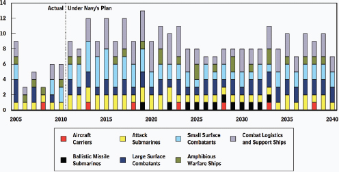
FIGURE 3-1 Projected U.S. Navy new-build requirements. SOURCE: Congressional Budget Office, “An Analysis of the Navy’s Fiscal Year 2011 Shipbuilding Plan,” May 2010.
planned replacement for the LCAC. The motivation for its design is to increase payload and improve reliability and maintainability.3 By making extensive use of aluminum for lightweighting, the SSC will exceed the LCAC in speed, payload, and range.
The marines also have an inventory of much smaller assault and reconnaissance boats that must be transported to theaters of operation. An expeditionary fighting vehicle (EFV) that could be launched from a safe distance offshore and then operate over land was, in concept, a model for lightweighting: it was intended to be heavily armored yet able to move quickly at sea and on land. It was canceled in January 2011 when it was behind schedule and over budget. Its replacement is likely to have a lower expectation for speed at sea.4 See Section 3.5.3.
3.1.3 Current State of Metrics
A very large empirical database has been accumulated based on building ships with steel. Maximizing the benefit of lightweight material will require long-term validation of design strategies and fabrication techniques for materials other than steel.
The lightweighting of U.S. DoD maritime platforms typically occurs at the design stage, because it is very difficult to retrofit large structural elements on complex ships. In particular, materials dramatically influence all aspects of a ship’s life cycle, and so the selection of materials for lightweighting ships must come early in the design process. Material mechanical properties determine a ship’s structural design, while manufacturing considerations greatly influence cost. Modular construction practices that maximize the size of lightweight structural elements fabricated before assembly can greatly reduce labor costs. As the DoD looks to get longer service life from its maritime platforms, the ability of material systems to withstand the ocean environment is paramount.
________________
3 Capt. C. Mercer, “Ship to Shore Connector: A Turning Point in Naval Ship Design,” September 9, 2010, available at www.navalengineers.org/flagship/.../ASNE_Luncheon_SSC_Turning%20Point%20in%20Naval%20Ship%20Design-9-8-10.ppt.
4 Matthew Potter. 2011. “U.S. Marine Corps Begins EFV Replacement Process—Updated.” Defense Procurement News. March 7. Available at http://www.defenseprocurementnews.com/2011/03/07/u-s-marine-corps-begins-efv-replacement-process/#ixzz1Md3Pu4fZ.
Material Properties
Material properties are typically determined at the coupon level in a laboratory environment. These data form the basis for developing “design allowable” mechanical property data. Novel materials require additional characterization, because naval designers have little or no empirical data to help formulate safety factors.5 As a minimum, the following material properties need to be quantified at the “coupon” or “panel” level to develop novel materials for lightweighting:
- Strength and stiffness. Required data include tension, compression, shear, and Poisson’s ratio values measured along three mutually orthogonal axes for anisotropic materials.
- Dynamic properties. Relevant dynamic material behavior includes impact, fatigue, and creep resistance.
- Environmental effects. Resistance to water absorption, corrosion, UV exposure, and fire are an important qualitative metric.
Design Criteria
The criteria used to design lightweight ship structures have a major influence on how well those materials are optimized. The design process begins with a detailed understanding of the loads that the ship will experience over its lifetime and how the structure will respond to those loads. A fairly good understanding of how mild steel ship structures perform in the ocean exists, but novel materials generally require larger design safety factors because of the more limited knowledge base on their performance.
Manufacturing Process
DoD ships are extraordinarily complicated engineered structures, built by joining plates into successively larger assemblies. A steel ship contains miles of weldments at the joints, making welding not only labor intensive but also critical to the ship’s structural integrity. Even small defects in weldments can grow to large cracks that eventually cause failures.6
With steel shipbuilding, plates, I-beams, and structural “tees” arrive at the shipyard with known physical properties, as specified by the yard and confirmed by quality assurance personnel. Construction using composite materials poses additional manufacturing risks, because laminators create the “plates” themselves in the shipyard. Metrics for shipbuilding reflect cost tradeoffs between weldability of materials and the skilled labor needed for materials that are more challenging to weld.
In-Service Performance
Selection of lightweight ship structural materials must also take into consideration the operational profile of the ship and how materials are expected to perform. In-service variables include expected sea states, operating speeds, temperature, docking and handling, coatings, equipment attachment, insulation, and passive fire protection.
Life-Cycle Costs
Life-cycle costs to be considered include the cost of materials, fabrication costs, maintenance costs, cost to inspect and repair, alteration costs, and the cost to recycle or dispose of the ship at the end of its useful life.7 Among competing systems, the one with the lowest procurement cost is unlikely to have the lowest life-cycle cost—steps taken to reduce procurement costs typically reflect tradeoffs that push costs to maintenance, repair, or other later stage in the life cycle. Various models have been developed to predict life-cycle costs, but it is virtually impossible
________________
5 See the discussion in “Uncertainty, Risk, and Design Factors” in Chapter 1 of this report.
6 W. Babcock and E. Czyryca. 2003. “The Role of Materials in Ship Design and Operation.” AMPTIAC Quarterly, Vol. 7, No. 3, pp. 31-36.
7 NAVSEA. 2004. “Draft Material Selection Requirements.” T9074-AX-GIB-010/1000. March.
to predict the operational threats and damage mechanisms that the system will face 20 years in the future. Thus, present design decisions generally do not reflect life-cycle costs.
3.2 BARRIERS AND KEYS TO SUCCESS FOR USE OF SELECTED MATERIALS
Advanced lightweight structural materials that show promise for application to DoD maritime platforms are diverse, each with its own technical challenges. Overcoming these challenges will require advances in material availability, design code maturity, qualification, manufacturing issues, and in-service performance. Because the committee views aluminum, composites, and high-strength steel as the most likely materials to be used for the primary structure of ship hulls in the near to mid-term, the following sections review barriers and keys to success for each material with respect to marine vessels.
3.2.1 Aluminum
Aluminum has been used as a ship construction material at least as far back as 1895, when the America’s Cup yacht Defender was built with aluminum skins over steel frames. Some early aluminum boats lasted only a few weeks in seawater, which isn’t surprising considering that copper or nickel was added to these early alloys and steel rivets were used, producing rapid galvanic corrosion.8
Bret Conner of Alcoa Defense’s Sea Systems reports that all surface combatants from 1947 until the DDG-51 had aluminum in their deckhouses, at which time the Navy switched back to steel due to cracking problems. Dr. Conner stresses the following to avoid past problems with aluminum marine construction:9
- Prevent fatigue cracking by analyzing stresses, especially at details, and performing a spectral fatigue analysis;
- Prevent stress corrosion cracking by using marine plate with greater than 3 percent magnesium certified to ASTM B928 (if service temperatures exceed 65°C or 150°F, choose an alloy with less than 3 percent magnesium such as 5454); and
- Avoid galvanic corrosion by isolating aluminum from steel.
In a presentation to the committee, Robert Sielski outlined the following research needs required to advance aluminum ship construction: material property and behavior; structural design; structural details; welding and fabrication; joining aluminum to steel; residual stresses and distortion; fatigue design and analysis; fire protection; vibration; performance metrics, reliability, and risk assessment; maintenance and repair; structural health monitoring; and emerging technologies.10,11 The largest identified knowledge gap is in the area of fatigue properties and fracture toughness, particularly dynamic fracture toughness.12 As shown in Figure 3-2, technological advances that reduce fatigue crack growth are needed to promote greater use of aluminum hulls for lightweighting.
3.2.2 Composites
Composite materials have the greatest potential to lightweight DoD maritime platforms, especially smaller, high-speed craft. However, they also present the greatest challenges to more widespread use. Every aspect of a
________________
8 Ship Structure Committee. 2007. “Aluminum Structure Design and Fabrication Guide.” SSC-452. NTIS#PB2007. Available at http://www.shipstructure.org/pdf/452.pdf.
9 Alcoa Defense, “Advantages of Aluminum in Marine Applications Webinar,” April 2010. Available at http://www.alcoa.com/global/en/news/webinar/alshipbuilding/alcoadefenseandabswebinar.pdf.
10 R.A. Sielski, Consulting Naval Architect—Structures (retired, Naval Sea Systems Command), “Lightweight Aluminum Structure for Ships and Craft,” presentation to the committee, September 20.
11 R.A. Sielski. 2007. “Research Needs in Aluminum Structure.” 10th International Symposium on Practical Design of Ships and Other Floating Structures. September.
12 Ibid.
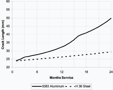
FIGURE 3-2 Predicted crack growth for a 4.39-m 32-knot craft. SOURCE: R.A. Sielski, “Aluminum Structure Design and Fabrication Guide,” Ship Structure Committee Report SSC 452, May 2007.
composite structure is created by shipbuilders from basic materials, which results in a great deal of variability in the materials’ mechanical properties. The myriad combinations of constituent elements in composite materials make it difficult to establish a comprehensive set of material design properties for all but the most common laminates.
Material Availability
Large ships use a massive quantity of structural material and can affect market availability of precursor and finished materials. This is especially true when novel, high-performance materials are used, such as the T700 carbon fiber for the DDG 1000 deckhouse. To meet their missions, military projects require materials that have higher levels of quality assurance than recreational applications do, which increase the cost to the government. However, greater demand for a product such as intermediate-modulus carbon fiber can also increase domestic production and create long-term price stability. Indeed, the DoD requirement for domestically sourced structural materials has provided justification for suppliers to develop production facilities in the United States.
Composite materials have stringent storage and handling requirements that can also influence the availability of a product at the shipyard. Resins have a limited shelf life, while reinforcements and cores must be kept dry.
Qualification Issues
The Navy has a number of technical warrant holders that must certify the safety of all material systems used to build ships. This arrangement accounts for the excellent safety record enjoyed by the fleet but discourages the use of new composite materials in lightweighting.
Manufacturing Variability
With the widespread use of vacuum-assisted resin transfer molding (VARTM), the variability of composite construction has certainly been reduced. Indeed, for most of the case studies described in this report, large panels were fabricated on flat laminating tables under very controlled conditions. The greater challenge is to join these panels and outfit the ship. Steel shipbuilding has long recognized the need to train and certify welders. Composite shipyards (i.e., those that build ships with composite hulls) are now instituting training and qualification programs, albeit generally with curricula proprietary to each shipyard. Shipbuilding with composite materials requires detailed process descriptions and a rigorous quality assurance program.
Inspection and Repair
With metallic structures, failures generally occur at welds and are visually apparent. In contrast, sandwich composite structures have failure modes that are not often apparent upon visual inspection. Delamination can occur within the laminate skins or between the skins and the core. The core can fail due to excessive stress or water ingress. Ultrasonic inspection techniques developed for the aerospace industry are difficult to scale up for the large surface areas and limited access of ships.
Repair techniques for large composite structures are very well developed and take advantage of the versatility associated with composite construction. Entire bow sections of commercial fishing vessels have been repaired after collisions by molding large, complex sections and joining them to the undamaged hull portions. Adequate strength properties can be achieved if sufficient scarf ratios are used.
Recycling
Because composites are not subject to corrosion, they will last longer than metal in a marine environment. Therefore, entire boats can be “recycled” for extended service through re-outfitting. When the structure needs to be permanently disposed of, however, recycling of composite shipbuilding materials remains a challenge. The current options are grinding for future use as filler material or incineration for power generation. Development of new recycling technologies is expected as wind turbine blades that were designed to last for 20 years reach the ends of their life spans.
3.2.3 High-Strength Steel
High-strength steel plate constitutes increasing portions of the hull structure in modern warships, surface combatants, and submarines for weight reduction, better stability, increased payload, increased mobility, and survivability. Naval shipbuilding accounts for nearly 50 percent of the total DoD requirement for alloy and armor steel plate. The U.S. Navy qualified HSLA-65 steel in 2005 by focusing on welded structure compressive properties, local stability of stiffener elements, plate buckling, lateral deformation of plates, fatigue strength, and grillage strength.13 HSLA-115 shows promise where material strength is paramount. The 16th International Ship and Offshore Structures Congress reports:
HSLA steels (low carbon, copper precipitation strengthened ones, whose strength and toughness are equivalent to those of HY steels, and that can be easily welded without preheating) can ensure a higher resistance when subject to sudden impact loads, like underwater explosions. On the other hand, there is no practical advantage in using such steels when cyclic loads are dominant as fatigue behavior is not dependent on the steel used but on the geometry of structural details and the quality of production. In this case the use of HSLA may lead to significant problems due
________________
13 E.J. Czyryca, D.P. Kihl, and R. DeNale. 2003. “NSWCCD, Meeting the Challenge of Higher Strength, Lighter Warships,” AMPTIAC, Vol. 7, No. 3, pp. 63-70. Available at http://msp.berkeley.edu/jomms/2007/2-10/jomms-v2-n10-p06-p.pdf.
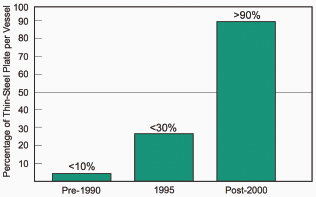
FIGURE 3-3 Thin steel plate use on Northrop Grumman Ship Systems ships. SOURCE: P. Huang, T.D. Dong, L.A. DeCan, and D.D. Harwig. 2003. “Residual Stresses and Distortions in Lightweight Ship Panel Structures.” Northrop Grumman Ship Systems, Technology Review Journal, Vol. 11, No. 1.
to the much more accurate production procedures required (welded joints, if not correctly carried out, may become fragile and more notch sensitive—thus more likely to experience fatigue cracks).14
At Northrop Grumman Ship Systems (NGSS), for example, the production ratio of thin-steel (10 mm or less) to thick-plate structures has risen to more than 90 percent. New designs are calling for the application of even thinner (e.g., 5 mm) high-strength steel grades to further reduce weight and improve performance.15Figure 3-3 shows the rapid increase in thin steel plate utilization for naval shipbuilding.
The increased use of lightweight steel panel structures has created challenges for shipbuilders to produce distortion-free ships. “Residual stresses and distortions induced by steel mill processing, as well as material-handling and manufacturing processes, such as cutting, tacking, and welding, cause progressive problems in downstream manufacturing/fabrication operations.”16 The referenced report suggests handling, cutting, and welding procedures designed to minimize local buckling, which is the dominant distortion phenomenon at NGSS.
3.2.4 Other Materials
A sandwich plate system (SPS) has been developed that uses steel skin panels and an injected elastomer core to create a sandwich structure that has very good out-of-plane mechanical properties. The technology is attractive for ship lightweighting, as the panel skins are composed of traditional shipbuilding steel, which is durable and easy to weld to the rest of the ship structure. One concern for naval applications would be the reduction in shear strength of the core material at elevated temperature.17
According to a 2003 assessment,18 the SPS technology has been shown to have equivalent or better fire safety
________________
14 16th International Ship and Offshore Structures Congress. Southampton, United Kingdom, August 20-25, 2006. P. 244. Available at http://www.issc.ac/img/r13.pdf.
15 T.D. Huang, D.D. Harwig, P. Dong, and L.A. DeCan. 2005. “Engineering and Ship Production Technology for Lightweight Structures.” Technology Review Journal, Vol. 13, No.1, Spring/Summer, pp. 1-26.
16 T.D. Huang, P. Dong, L.A. DeCan and D.D. Harwig. 2003. “Residual Stresses and Distortions in Lightweight Ship Panel Structures, Northrop Grumman Ship Systems.” Technology Review Journal, Vol. 11, No. 1.
17 Lloyds Register. 2006. “Provisional Rules for the Application of Sandwich Panel Construction to Ship Structure.” April. Available at http://www.ie-sps.com/downloads/419.pdf.
18 M.A. Brooking and S.J. Kennedy. 2003. “The Performance, Safety and Production Benefits of SPS Structures for Double Hull Tankers.” Intelligent Engineering, Ltd. August.
to traditional steel structure when both are protected by structural fire protection. Of greater concern would be areas that do not have structural fire protection, such as the top side of decks and the exterior side of bulkheads. The same assessment also states:
If an SPS panel is directly exposed to fire for an extended period then the elastomer core acts as sacrificial layer on the fire side (ablation) and gases from the elastomer surface vent into the fire side through temperature controlled pressure release valves.19
Without an integral core, the SPS cannot function as a sandwich structure and panel-buckling resistance would be greatly compromised. The Navy would certainly require fire testing to the hydrocarbon fire test criteria, which use roughly twice the fire insult used to qualify SPS for commercial ship applications.
3.3 LIGHTWEIGHTING OPPORTUNITIES FOR MARITIME VEHICLES
Ship designers have been striving to lightweight their craft for as long as people have ventured offshore. A hull moving through the ocean encounters a great deal of resistance from the water, so boats with less displacement encounter less resistance and can move faster. Reducing weight high up increases a vessel’s stability and survivability. The potential for lightweighting modern warships is quite large because of the ability to create multifunctional structures.
Ship structure needs to keep the ship afloat, resist wave loads, survive combat conditions, insulate the interior, and resist fires. Modern warships are increasingly incorporating apertures for integrated sensors.20 With advanced computer-aided design and simulation tools, load conditions and structural response can be predicted more accurately, allowing for further weight optimization. Naval architecture is a classic “systems engineering” discipline that uses an iterative optimization process.
3.3.1 Primary Hull Structure
The potential for lightweighting the primary hull structure of very large ships is limited by stiffness and fatigue considerations. To date, the largest aluminum ship is 127 m and the largest composite ship is 75 m. These milestones will likely be surpassed as more at-sea experience with lightweight vehicles accumulates. However, even ships of 75 m or less are very useful for many DoD maritime missions that require speed and stealth. An example—the joint high-speed vehicle—is described in Section 3.5.6.
Lightweight materials are especially attractive for novel hull forms, such as multihulls, surface effect ships (SES) and hovercrafts. These ships require lightweight hulls yet have more surface area than their monohull counterparts. Ships that achieve high-speed performance by planning or other means of dynamic support must be lightweight in order to perform as designed.
Several technologies will help to lightweight primary hull structures. Ubiquitous structural health monitoring using low-cost, wireless sensors or sensors that are integral with hull plating will permit optimization of scantlings. Design criteria for structural details are currently based on previously observed damage. With real-time strain data, the ship designer will be better equipped to optimize the structure. These data are especially needed in the wave slam areas of high-speed ships.
Investigating multifunctionality opportunities can also help to optimize primary hull structure. Parasitic weight is added to hull structures in order to achieve thermal insulation, structural fire protection, and corrosion and biofouling resistance. Developing material systems that incorporate all these functions will not only lightweight the ship but also decrease required manufacturing and maintenance labor.
________________
19 Ibid.
20 Such as various types of radar systems. See, for example, “Use of Composite Materials for Weight Reduction in Navy Applications,” presentation to the committee by G. Camponeschi, Naval Surface Warfare Center, July 21, 2010.
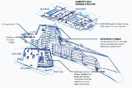
FIGURE 3-4 DDG Zumwalt destroyer composite deckhouse superstructure. SOURCE: Illustration by Karl Reque, from M. LeGault, 2010, “DDG-1000 Zumwalt: Stealth Warship,” Composites Technology, February.
3.3.2 Deckhouses
Deckhouses are the first place ship designers look for lightweighting opportunities. This is because deckhouse structure is not expected to contribute to hull girder strength and stiffness, thus making it possible to use a lower modulus material.
For example, the 160 ft long by 70 ft wide by 65 ft high deckhouse of the Navy’s newest destroyer will be a composite structure built using carbon fiber, vinylester resin, and a balsa core. Use of composites will allow the Navy to reduce topside weight, platform signature and to integrate apertures into the structure.21 According to Barry Heaps, Northrop Grumman Shipbuilding program manager/director DDG-1000 Deckhouse, carbon fiber was used instead of E-glass because “the structural load requirements for the … deckhouse are significantly higher than those for LPD masts.”22Figure 3-4 illustrates the composite deckhouse.
3.3.3 Secondary Structure
Large ships have thousands of square meters of secondary structure that could be lightweighted if adequate structural and fire resistance characteristics can be achieved. The LASS project (Section 3.5.5) addressed fire performance issues with cost-effective solutions. The study showed that sandwich composite panels have excellent out-of-plane mechanical properties required of internal decks and bulkheads.
Corrugated stainless steel panels (LASCOR) have also been proposed for secondary structure on naval ships. ATI reports that ATI 2003® lean duplex stainless is being used to manufacture LASCOR panels for personnel safety
________________
21 E.T. Camponeschi. 2010. “Carbon Fiber Composites in DDG 1000.” Presentations to the committee in October 2009 and on July 21, 2010.
22 M.R. LeGault. 2010. “DDG-1000 Zumwalt: Stealth Warship.” Composites Technology. February. Available at http://www.compositesworld.com/articles/ddg-1000-zumwalt-stealth-warship.
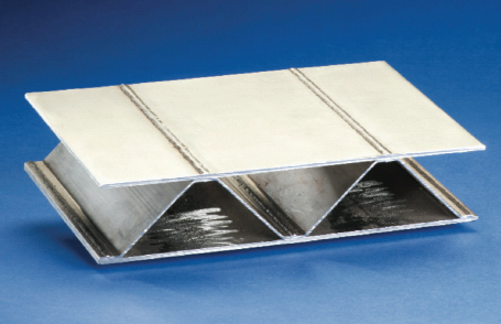
FIGURE 3-5 LASCOR (LASer-welded corrugated CORe) panel. SOURCE: S. O’Connor. 2010. “U.S. Navy Uses Proprietary ATI Alloy for New Destroyer Ships.” ATI Defense. March.
barriers on the DDG 1000 destroyer ship. ATS successfully manufactured numerous large (78 × 240-inch) LASCOR panels for a number of structural tests.23Figure 3-5 shows the structural configuration of LASCOR panels.
3.3.4 Outfitting
Reducing the weight of DoD maritime platforms by lightweighting outfitting elements is generally beyond the scope of this report but it is instructive to look at opportunities as part of the overall ship design process. Composites have been used for piping, pump housings, ventilation ducts, ladders, gratings, electrical enclosures, shafts, and foundations. The Navy has also considered titanium piping and heat exchangers.
3.3.5 Unmanned Maritime Vehicles
The committee has not assessed the potential for lightweighting in unmanned surface vehicles (USVs) or unmanned underwater vehicles (UUVs). A review of the history of USV development notes,
As global positioning systems have become more compact, effective, and affordable, unmanned surface vehicles have become more capable. Despite this proliferation of proven prototypes there are few USVs on the market or in use, especially compared to their unmanned undersea vehicle (UUV) cousins. This paper concludes with a discussion of some emerging new trends in USVs and the challenges to wider adoption of the technology.24
________________
23 S. O’Connor. 2010. “U.S. Navy Uses Proprietary ATI Alloy for New Destroyer Ships.” ATI Defense. March. Available at http://www.atimetals.com/defense/docs/ATI2003Destroyer.pdf. Last accessed November 18, 2011.
24 Justin Manley. 2008. “Unmanned Surface Vehicles, 15 Years of Development.” 978-1-4244-2620-1/08. MTS/IEEE OCEANS 2008 Confer ence. Quebec City. Available at http://www.oceanicengineering.org/history/080515-175.pdf. Last accessed October 19, 2011.
3.4 LONG-TERM CONCERNS IN LIGHTWEIGHTING MARITIME VEHICLES
Although high-performance racing boats are often the genesis of lightweighting concepts, the DoD requires platforms that can be supported over an expected 40-year life. Initial decisions about material selection, fabrication, and documentation can greatly influence the long-term value of a maritime asset.
3.4.1 Design Methodology
One of the most cost-efficient ways to lightweight ships is to more accurately predict local stresses and failure modes, as described in Section 3.2.1. Ships are by necessity conservative structures due to uncertainty about the ocean environment and how the ship will interact with it. By definition, waves are repetitive forces, so fatigue performance is of paramount importance. For composite materials, crack propagation is not an area of concern but delamination and secondary bond areas (joints) are. For metallic structures, weld areas require additional design attention. Long-term optimization of ship design requires validation of structural performance. Wave damage to a Mark V Special Operations Craft, shown in Figure 3-6, highlights the pressing need for a better understanding of both effective craft design and material capabilities and limitations. The Navy design community is acutely aware of the need for new models that account for corrosion; material degradation (sensitization, fatigue cracking); and deformation for life prediction and life-cycle management of platform structures.25
3.4.2 Material Availability
Regardless of the materials used for large maritime platforms, the massive quantity of structural material required can affect market availability of precursor and finished materials. This is especially true of novel, high-performance materials, such as the T700 carbon fiber for the DDG 1000 deckhouse. The following paragraphs address the material availability issues for composites, aluminum, and steel.
Composite structures require a number of individual materials, each of which is subject to its own supply challenges. The price of resin systems is directly proportional to the price of oil. Market demand from other industries also influences resin availability and cost. High-performance fibers, such as carbon, are produced in quantities and priced to meet the demands of the aerospace market and will remain a challenge for shipbuilders to utilize on a large scale. Specialized core material is also produced in limited quantities.
Aluminum ship construction costs are being driven down by the greater use of specialty extrusions, such as stiffened panels and weld joint products shown in Figure 3-7. The Navy Metalworking Center reports that the Lockheed Martin Team Littoral Combat Ship design makes extensive use of stiffened aluminum panels for construction of the ship’s superstructure. These panels are built up from extruded aluminum shapes using friction stir welding (FSW) as the joining method.26 In order to support ships built with these specialty products, their long-term availability must be assured.
The Navy’s aircraft carrier program certainly has benefited by incorporating HSLA-115 in the design of the flight deck to improve stability. However, the specialized alloy is produced by only one supplier, which eliminates the possibility of any price competition.
3.4.3 Domestic Manufacturing Capability
Navy program managers are acutely aware of the sources of raw materials that they use and the stability of those regions. At a recent U.S. Office of Naval Research (ONR) energy conference it was noted that while imported oil may originate from unstable global regions, the lithium required for a battery-based transportation system is also not a domestic resource; most is mined in Bolivia. While titanium is attractive for maritime construction due to its light weight, high strength, and corrosion resistance, Russia is currently the primary source for most of this material.
________________
25 P.E. Hess, 2008. “Structural Reliability Program.” ONR Program Code 33. August.
26 M.T. Smitherman and K.J. Colligan. 2008. “Low-Cost Friction Stir Welding of Aluminum for Littoral Combat Ship Applications.” Navy Metalworking Center. August.

FIGURE 3-6 Wave damage to Mark V special operations craft. SOURCE: J. Grimsley and E.G. Hatchell. 2008. “Computational Tools for Combatant Craft.” NSWCCD, SeaFrame, Vol. 4, Issue 2.
The United States has a strong domestic capability to build lightweight boats, driven primarily by the demand for high-quality yachts and commercial crew boats.27 Some manufacturers have demonstrated the ability to produce military prototypes for evaluation, but these rarely transform into production efforts due to government contracting requirements. Indeed the initial Littoral Combat Ship incurred cost overruns by both vendors due to failures to effectively use earned value management procedures required of major defense contractors.28 Warships typically have more significant outfitting requirements than commercial vessels of the same tonnage, which increases cost and management complexity.
In a 2006 study commissioned by the ONR, it was found that mid-tier shipyards in the United States (i.e., those able to build up to a 400-ft medium-size combatant), “have limited knowledge of naval vessels.”29 Mid-tier shipyards in the United States were rated lower, on average, than international mid-tier shipyards and U.S. first-tier shipyards on every criterion (pre-erection activities, ship construction and outfitting, and five others).30 As a consequence of this situation, the Navy has looked overseas for this expertise—Scandinavia for composites, Australia for aluminum, and Italy for high-strength steel. Technology transfer programs are then used to establish U.S. partners, which disrupts the Navy’s traditional design and oversight relationships with established shipyards.
________________
27 According to the National Marine Manufacturers Association’s 2010 Recreational Boating Statistical Abstract, “Recreational boating remains an important contributor to the U.S. economy, generating $30.4 billion in sales and services in 2010….”
28 C.J. Castelli. 2008. “Audit Exposes Failed Management of Troubled Littoral Warship.” Inside the Navy. February 4.
29 First Marine International Ltd. 2006. “Capabilities Study of Mid-Tier U.S. Shipyard.” November. Available at http://www.cnst.us/Projects/capabilities_assessment.html.
30 First Marine International Ltd. 2007. “Findings for the Global Shipbuilding Industrial Base Benchmarking Study, Part 2: Mid-Tier Ship yards, Final Redacted Report.” February 6.
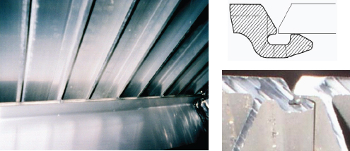
FIGURE 3-7 Aluminum stiffened panels (left) and weld joint (right) specialty extrusions. SOURCE: Brett Conner. 2010. “Advantages of Aluminum in Marine Construction.” Segment Leader, Sea Systems, Alcoa Defense, Alcoa.
3.4.4 Structure Inspection and Repair
For maritime vehicles in particular, survivability refers not just to combat but perhaps more so to the effects of the environment (e.g., weather, waves, salt damage). The ultimate survivability of a ship rests on the ability to observe and repair damage before it becomes catastrophic. Benign failure modes, such as stiffener versus hull plating failure, form the basis for long-term structural integrity. However, minor failures must be observed and repaired. Many high-speed ship designs rely on complex hull structures that are not readily available for structural inspection, such as catamaran and surface effect ship hulls. Visual inspection is further hampered by thermal insulation or structural fire protection that covers hull plating and internal framing. Lightweighting strategies must include non-destructive evaluation (NDE) methodologies tailored to materials and structural systems employed. Material-specific repair procedures must also be prepared and validated.
3.4.5 Environmental Impact
The long-term environmental impact of a selected lightweight ship construction material includes overall life expectancy, corrosion resistance (need for preservation coatings), ease of recycling and the effects of catastrophic failure (sinking). Aluminum has a good track record for recycling; according to the Aluminum Association, 70 percent of the aluminum ever made is still in use today.31 There is a vibrant industry for recycling steel from large ships after their useful life has expired, albeit in countries where labor costs are very low. Composite structures are more challenging to recycle. The material can be ground up for use as filler but in order to reuse the materials in a more virgin form the resin and reinforcement must be separated, which is an energy-intensive operation at this point.
3.5 EXAMPLES OF LIGHTWEIGHTING IN MARITIME VEHICLES
This section describes the role of lightweighting in a range of maritime vehicles—from U.S. and international maritime programs, and including a variety of vehicles, technologies, and maturity.
________________
31 The Aluminum Association. 2008. “Aluminum Industry Takes Aim at Climate Change, More Efficient Technologies, Processes Point Way to Reducing Greenhouse Gas Emission.” Available at http://www.aluminum.org/AM/Template.cfm?Section=Home&template=/CM/HTMLDisplay.cfm&ContentID=23520.
3.5.1 New Composites Developed for Advanced Destroyers32
The Arleigh Burke class destroyer is a multimission warship with offensive and defensive capabilities. DDG 51 Arleigh Burke was ordered in 1985, commissioned on July 4, 1991, and tested at sea throughout 1992. Since then, 21 destroyers using the original (Flight I) design have been commissioned, followed by 7 of the Flight II variant, and more than 25 of the Flight IIA variant, which was first commissioned in August 2000.
DDG: Technological Progress but Canceled Program
The extensive testing required to certify new materials accounts for the excellent safety record enjoyed by the fleet but provides a challenge for lightweighting. Although the DDG 1000 program was limited to three ships, the composite materials developed, tested, and certified for the DDG 1000 deckhouse are available for future applications.
The destroyers became heavier with each increase in capability. The Flight IIA design added mine-avoidance capability, a pair of helicopter hangars, blast-hardened bulkheads, distributed electrical systems, and advanced networked systems. It achieves 30 knots or more in open seas and displaces 9,648.4 metric tons at full load.
The next generation of advanced destroyers, initially intended to replace the DDG 51 platform by 2012, is the DDG 1000 (Zumwalt class). The DDG 1000 uses modern technology and takes advantage of lightweighting by, for example, having a composite DDG 1000 Deckhouse with integrated apertures and low signature profile. Two Zumwalt-class destroyers, of an anticipated 8-12, are under construction. In 2008, however, the decision was made to end the DDG 1000 program after three ships, and to modernize the DDG 51 fleet. According to Navy spokesman Lt. Clay Doss:
We need traction and stability in our combatant lines to reach 313 ships, and we should not raid the combatant line to fund other shipbuilding priorities…. Even if we did not receive funding for the DDG 1000 class beyond the first two ships, the technology embedded in DDG 1000 will advance the Navy’s future surface combatants.33
The DDG 1000, with its advanced functional capabilities, costs more per ship than its predecessor; however, it has contributed to the use of new composite materials in shipbuilding. According to Northrop Grumman:
During the DDG 1000 engineering development phase, NGSB [Northrop Grumman Ship Building] produced more than 6,000 carbon fiber/vinyl-ester test articles that were successfully tested and validated for ship designs in radar cross section, co-site, material properties, joints, fire, corrosion, shielding effectiveness, fragmentation and blast.34
This level of testing is typical for what the U.S. Navy considers to be a “new” shipbuilding material. The Navy has a number of Technical Warrant Holders that must certify the safety of all material systems used to build ships. Thus, new materials are introduced via a cautious and time-consuming process, which accounts for the Navy’s excellent safety record but is a deterrent to introducing new materials for lightweighting.
3.5.2 Two Designs—Aluminum and High-Strength Steel—for Littoral Combat Ships35
The Navy started the Littoral Combat Ship (LCS) program in 2002, as a small, fast, relatively inexpensive combat ship. Interchangeable mission modules would deploy manned and unmanned vehicles and sensors in support of mine, undersea and surface warfare missions. Other intended missions include peacetime engagement, maritime intercept operations, and homeland defense.
Light weight is essential to the performance of the LCS. It displaces about 3,000 tons (about the size of a light
________________
32 This section draws on factual descriptions drawn from http://www.navy.mil/navydata/fact_display.asp?cid=4200&tid=900&ct=4. Last accessed June 10, 2011.
33 Quoted in C. Cavas, 2008, “DDG 1000 Program Will End at Two Ships,” Defense News, July 22.
34 C.P. Cavas. 2008. “DDG 1000 Deckhouse on Track.” Defense News. September.
35 This section draws on factual descriptions from http://www.navy.mil/navydata/fact_display.asp?cid=4200&tid=1650&ct=4, accessed June 10, 2011; and R. O’Rourke, 2011, “Navy Littoral Combat Ship (LCS) Program: Background, Oversight Issues, and Options for Congress,” RL33741, Congressional Research Service, April 29.
frigate or a Coast Guard cutter), allowing it to operate in coastal waters that are inaccessible to Navy cruisers and destroyers. It has a maximum speed of more than 40 knots, compared with just over 30 knots for the Navy’s larger surface combatants. And it has a core crew of 40, plus 35 additional sailors to operate the mission packages, for a total of 75, compared with more than 200 sailors for a Navy frigate.36
The first two LCSs were delivered to the Navy by Lockheed Martin and General Dynamics in 2008 and 2009. As the costs escalated, the Navy terminated its cost-plus contacts with Lockheed Martin and General Dynamics in 2007. Fixed-price contracts for the next two LCSs were awarded to Austal USA/General Dynamics and Lockheed Martin in 2009, with the intention of choosing one of the teams to produce 10 additional ships. Figure 3-8 shows the all-aluminum trimaran built by the Austal USA team and the high-strength steel hull/aluminum deckhouse monohull from the Lockheed Martin team.
LCS: Different Materials, Same Missions
The lightweight construction needed to achieve the littoral combat ship’s speed, maneuverability, and shallow draft did not depend on a single design and material. The aluminum and high-strength steel versions both met the Navy’s specifications. It is too early to compare their long-term performance.
When both bids came in under the cost cap per ship, the Navy sought and in December 2010 received congressional approval to purchase 10 ships from each team.37 LCS 3 and LCS 4 are now under construction and four more LCS are under contract. If the Navy’s follows its 30-year shipbuilding plan for 55 sea-frames and 64 mission packages, the LCS would be one-sixth of the Navy’s total fleet. Because of the likelihood of cost-effective upgrades to replace mission modules, the platform—which is not easily upgraded—assumes greater prominence as a determinant of life-cycle costs and vessel retirement.38
3.5.3 Lightweighting the Marine Corps Expeditionary Fighting Vehicle While Maintaining Survivability
EFV: Lightweighting for an Emerging Threat
The considerable effort made to lightweight the expeditionary fighting vehicle throughout its development nonetheless fell short of the breakthrough strategies needed for the EFV to achieve its objectives. Lightweighting strategies need to keep pace not only with the development cycle but also with the performance needed to face emerging or unknown threats.
Figure 3-9 shows the expeditionary fighting vehicle (EFV) that was being developed by the Marine Corps as a successor to the Marine Corps’ existing amphibious assault vehicle (AAV), Amtrac (from “Amphibious Tractor”). It was intended to transport 17 troops from ships offshore to their inland destinations at higher speeds and from farther distances than the legacy AAV. The prototype EFV has a ballistic-grade aluminum hull to facilitate speeds of up to 25 knots in open water.
The U.S. Government Accountability Office (GAO) reported that “the EFV program has worked to provide improved protection against improvised explosive devices (IEDs) and other threats, but risks remain.”39 It noted that the current design is projected to have a level of protection generally comparable to the AAV with its armor appliqué. New aluminum alloys and welding processes to be introduced on production vehicles were expected to provide additional protection. In addi-
________________
36 R. O’Rourke. 2011. “Navy Littoral Combat Ship (LCS) Program: Background, Oversight Issues, and Options for Congress.” RL33741. Congressional Research Service. April 29.
37 C.P. Cavas. 2010. “Navy Awards LCS Deals to Lockheed, Austral.” Navy Times. December 26. Available at http://www.navytimes.com/news/2010/12/navy-awards-lcs-contracts-to-lockheed-martin-austal-122910w/. Last accessed May 18, 2011.
38 M. Collette. 2011. “Hull Structures as a System: Supporting Lifecycle Analysis.” ASNE [American Society of Naval Engineers] Day 2011 Proceedings. Available at http://www.navalengineers.org/publications/symposiaproceedings/Pages/ASNEDay2011Proceedings.aspx.
39 U.S. Government Accountability Office. 2010. Expeditionary Fighting Vehicle (EFV) Program Faces Cost, Schedule, and Performance Risks. GAO-10-758R Defense Acquisitions. July.
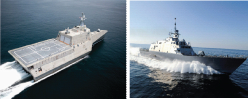
FIGURE 3-8 Littoral combat ship trimaran (Austal USA–left) and monohull (Lockheed Martin–right). SOURCE: CAPT Mike Good, Program Manager LCS Mission Modules, “Littoral Combat Ship (LCS) Program Overview,” Northwest Florida Defense Coalition, May 14, 2009.
tion, the ONR ManTech program developed a composite forward ramp with integral blast protection to alleviate the need to add aluminum appliqué as a kit once the EFV reaches shore.40
The GAO report also noted that difficulties meeting vehicle weight requirement resulted in: reduction in highspeed transit sea state capability from 3 ft to 2 ft significant wave height; proposed removal of integrated nuclear, biological, and chemical protection; and reduction in required vehicle land range following amphibious landing.
Although the Marines had planned to procure 600 EFVs, the program was canceled in early 2011 for budgetary and performance reasons.41 The Secretary of Defense noted that Hezbollah militants struck an Israeli ship in 2006 with a missile that has a range of 75 miles.42 The evolving threat had outpaced the performance specifications’ the EFV was designed for a 25-mile ocean mission range—and even after transiting this distance from the Seabase it would need to be refueled once ashore.
3.5.4 High-Strength Steel in Aircraft Carriers43
The aircraft carrier fleet consists of 10 Nimitz-class ships (CVNs 68 through 77) and the Enterprise (CVN 65), all nuclear-powered. The Gerald R. Ford class carrier (CVN 78) is the successor to the Nimitz class and will replace the Enterprise. The new design allows more frequent sorties and requires almost 800 fewer sailors, which will reduce operating costs. The Navy estimates that the CVN 78 will save $5 billion in life-cycle costs compared with Nimitz-class ships.
The Navy has considered composite construction for portions of the island structure on the CVN 78 aircraft carrier to correct an anticipated high center of gravity and starboard list condition. However, the platform’s shipbuilder believes that the manufacturing technology is not mature enough to incorporate composite construction for the island or in shipboard piping systems. Lightweight steels (HSLA 65 and HSLA 115) have been identified as “critical technologies” for the CVN 78, with the potential to save 700 tons and 175 tons, respectively.
________________
40 Ibid.
41 A good history of the EFV is given in “The USMC’s Expeditionary Fighting Vehicle (EFV),” Defense Industry Daily, June 13, 2011, available at http://www.defenseindustrydaily.com/the-usmcs-expeditionary-fighting-vehicle-sdd-phase-updated-02302/, last accessed August 5, 2011.
42 T.V. Brook. 2010. “Marines Forge Ahead with New Landing Craft.” USA Today. May 5.
43 This section draws on http://www.navy.mil/navydata/fact_display.asp?cid=4200&tid=200&ct=4; and R. O’Rourke, “Navy Ford (CVN-78) Class Aircraft Carrier Program: Background and Issues for Congress,” Congressional Research Service, August 24, 2010.
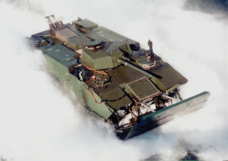
FIGURE 3-9 Expeditionary fighting vehicle. SOURCE: U.S. Marine Corps. Available at http://www.efv.usmc.mil/.
CVN 78: Adapting a Qualified Material
The time to qualify HSLA 115 was reduced by heat-treating lower-strength steel rather than using a unique steel composition, which would have required a lengthy program to develop and certify welding procedures.
The Office of Naval Research recently reported that “successful vendor qualification of first article, full-size production plates of HSLA-115 (named for its increased minimum yield strength of 115 ksi), weld qualification evaluations and explosion testing and completion of Material Selection Information (MSI) certification data have been achieved.”44 The project team45 was able to qualify HSLA-115 using HSLA-100 welding procedures because the higher-strength steel was produced by heat-treating HSLA-100 rather than an initially proposed solution using 10Ni steel.
3.5.5 Lightweight Construction Applications at Sea
Sweden’s recent LASS project (lightweight construction applications at sea) was aimed at improving the efficiency of marine transport and increasing the competitiveness of the Swedish shipping industry. The target was to accomplish this through the development and the demonstration of practical techniques for using lightweight
________________
44 Office of Naval Research. 2009. “HSLA-115 Procured for Fabrication of CVN 78: Will Reduce Top-Side Weight/Lower Center of Gravity.” Available at http://www.onr.navy.mil/en/Media-Center/Press-Releases/2009/HSLA-115-Procured-Fabrication-CVN%2078.aspx.
45 Participants: PEO Aircraft Carriers; Naval Surface Warfare Center, Carderock Division; Naval Sea Systems Command; Northrop Grum man Shipbuilding-Newport News; Navy Metalworking Center; Arcelor-Mittal Steel; DDL Omni Engineering; Puget Sound Naval Shipyard; and Navy Joining Center.
materials for ship construction. The LASS project demonstrated that 30 percent weight saving could be achieved for major structural elements of the maritime platforms shown in Figure 3-10.
The project focused on developing lightweight fire protection systems for aluminum and composite construction. “Typical weight reduction when using aluminum or FRP composites have been over 50 percent compared to a conventional steel design, and cost analysis has demonstrated possible payback times of 5 years or less for the lightweight material investment, primarily through reduced fuel consumption.”46
LASS: Economic Viability of Lightweight Ships
The accomplishment of the LASS project in fire protection and lightweight deckhouses, among others, reflects a conscientious effort by Scandinavian countries to address the technological challenges and develop commercial opportunities for their lightweight, composite shipbuilding expertise. By maintaining a strong industrial base in marine composite R&D and construction, these countries are able to build lightweight naval vessels more economically.
3.5.6 Joint High-Speed Vessel Based on a Commercial Catamaran47
The joint high-speed vessel (JHSV) shown in Figure 3-11 is a commercially designed high-speed catamaran adapted for U.S. Army and Navy requirements. The Australian shipbuilders Austal and Incat both produce fast catamarans that are widely used as commercial ferries. The Army, Navy, and Marine Corps leased catamarans from the two companies before establishing JHSV requirements. The bid was won by Austal USA, Alabama, for 8 ships, though more recent plans call for 18. The JHSV was able to enjoy a compressed procurement schedule because it is not classed as a warship and was considered to be a “non-developmental” item.
The vessels will be used for fast intra-theater transportation of troops, military vehicles, and equipment. Compared with transport by ferry or amphibious shipping, the JHSV does not need a full-service port and can cut the time of transporting a Marine battalion by more than half. The same transport would take 14-17 “lifts” from C-17 aircraft, at about four times the cost of using the JHSV. The ships will be capable of transporting 600 short tons 1,200 nautical miles at 35-45 knots. They will connect to roll-on/roll-off discharge facilities and on/off-loading a combat-loaded Abrams Main Battle Tank (M1A2).48
JHSV: Adapting a Commercial Design
The existence of a related commer cial product can accelerate military use of lightweight-ing technology by reducing the time needed for design, manufacturing process development, and qualification. By leasing commercial vessels, the Department of Defense gained experience before procuring the related joint high-speed vessel.
3.5.7 Redesign of the Mark V Special Operations Craft49
The Mark V special operations craft (SOC) is a medium-range, high-speed vehicle used to take U.S. Navy SEALs into and out of operations where the threat to these forces is low to medium. “It is also used for limited coastal patrol and interdiction. It is designed to carry 16 fully equipped Navy SEALs through rough seas at speeds of greater than 50 knots to destinations as far as 800 km from their base, on missions lasting as long as 12 hours.”50
________________
46 T. Hertzberg. 2009. “LASS, Lightweight Construction Applications at Sea.” SP Technical Research Institute of Sweden. March.
47 This section draws on http://www.defenseindustrydaily.com/jhsv-fast-catamaran-transport-program-moves-forward-updated-01535/ and NAVSEA Public Affairs, “Keel Laid for First Joint High Speed Vessel,” July 2010.
48 NAVSEA Newswire. 2010. “Keel Laid for First Joint High Speed Vessel.” July. Available at http://www.navsea.navy.mil/Newswire2010/22JUL10-01.aspx.
49 This example draws on G. Gardiner, “Composites Take the Hit in U.S. Navy Patrol Boat,” High-Performance Composites, September 2008; and the “Mark V Special Operations Craft,” available at http://discoverspecialforces.com/special-forces-vehicles/mark-v-special-operations-craft/, last accessed October 19, 2011.
50 G. Gardiner. 2008. “Composites Take the Hit in U.S. Navy Patrol Boat.” High-Performance Composites. September.
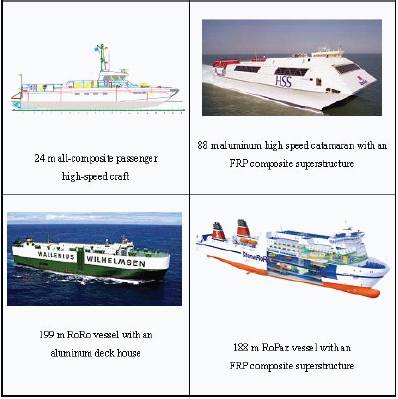
FIGURE 3-10 LASS project maritime platforms. SOURCE: LASS project. Available at http://www.lass.nu/.
Mark V: A Difficult Balance in Design
The initial Mark V achieved its goals for speed and range through lightweighting, at a cost of frequent injuries to its crew. A lack of robust design tools for the redesign limited the lightweighting potential of carbon fiber construction.
The original competition in 1994 was among three designs: a Kevlar hull, an aluminum monohull, and an aluminum catamaran hull. The contract was awarded to Halter Marine of Gulfport, Mississippi, for its aluminum monohull design. Using an expedited acquisition process, Halter Marine delivered its first Mark V 18 months later, and all 20 were delivered by 1999.
The aluminum Mark V achieved its survivability and performance goals—but was very rough on the warfighters, who experienced excessive fatigue and sustained injuries such as sprained ankles, whiplash, and spinal injuries. “Crews were being subjected to 4- to 5-G impacts one to two times per minute during operations at cruising speed (35 knots) in 3-ft to 4-ft (0.91 m to 1.22 m) waves,”51 with impacts from larger waves reaching 20 Gs.
The Navy sought to increase comfort for the crews without losing any of the Mark V’s performance capabili-
________________
51 Ibid.
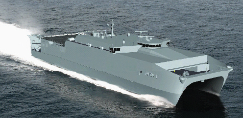
FIGURE 3-11 Joint high-speed vessel (JHSV). SOURCE: JHSV Technical Brochure, Austal USA, October 2009.
ties. Maine Marine Manufacturing of Portland collaborated with the University of Maine’s Advanced Engineered Wood Composites (AEWC) Center (Orono, Maine) under a 4-year contract with the Office of Naval Research to redesign the Mark V using composites and produce a prototype for Navy testing. The lack of robust design tools posed a challenge, which was met in part by AEWC’s development of a method for testing wave impact on alternative structures and laminates. According to Maine Marine Manufacturing’s president and CEO, David Packhem Jr., the carbon fiber/epoxy resin/foam core Mark V “is actually 50 percent stronger and slightly lighter than its aluminum predecessor, and we expect that Navy testing will confirm that we’ve been able to reduce transmission of slamming loads.”52 The composite Mark V is shown in Figure 3-12.
3.5.8 Demonstrating the Feasibility and Benefits of the Advanced Enclosed Mast/Sensor System53
AEM/S: Lightweight, Multifunctional, Detachable
The AEM/S is a large composite structure that forced the development of analytical methods, structural details, and joining technology. The advanced technology demonstration process allowed the Navy to work in close partnership with the fabricator to develop the new technology that made the AEM/S possible.
The Navy’s Advanced Enclosed Mast/Sensor (AEM/S) system used innovative materials, structures, and manufacturing techniques, yet it could be produced in a shipyard environment. The system is multifunctional—it encloses a ship’s vast array of radars and sensors typically exposed on masts, thus protecting sensors from harsh weather, improving their performance, and reducing the need for maintenance. It is designed to be detachable so that it can be easily replaced by the next generation. The composite AEM/S structure reduces the ship’s radar signature and its weight. The faceted nature of the AEM/S structure provides the necessary flat sur-
________________
52 Ibid.
53 This example draws on J.H. Meloling, 2001, “Advanced Enclosed Mast/Sensor (AEM/S) System,” SSC San Diego Biennial Review, August; and USSNY website, http://www.ussny.org/faq.php.
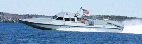
FIGURE 3-12 Composite Mark V special operations craft. SOURCE: Available at http://hodgdondefensecomposites.com/projects.shtml.
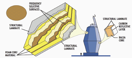
FIGURE 3-13 AEM/S sandwich construction concept. SOURCE: Schematic from Northrop Grumman in J.H. Meloling, “Advanced Enclosed Mast/Sensor (AEM/S) System,” SSC San Diego Biennial Review, August 2001.
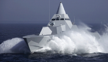
FIGURE 3-14 The Visby class corvette. SOURCE: Photo by Kockums AB, “The VISBY Class Corvette: Defining Stealth at Sea,” 2006. Available at www.kockums.se.
faces for mounting phased array antennas. Figure 3-13 shows how frequency selective surfaces are used to control what signals are transmitted through the structure.
The AEM/S was fielded as an advanced technology demonstration (ATD) on the on the USS Arthur W. Radford (DD 968) in 1997. It survived 100-mph-plus winds and an accidental ship collision, and demonstrated the ability to design and fabricate enclosed mast structures for Navy ships. The AEM/S is now the baseline design used on the LPD (Landing Platform Dock)-17 class of ships.
3.5.9 Lack of Domestic Production Capability for the Fast Response Cutter
FRC: Technology Transfer Failure
Despite a partnership between the Swedish company Kokums, builder of the Visby class FRC, and Northrop Grumman Shipbuilding, design problems in the United States caused the planned technology transfer to fail. As a result, the United States has no organic capability to build lightweight composite warships. An understanding of what went wrong might help avert such problems in the future.
The Visby class ship was developed by the Swedish Navy as a fast, stealthy corvette that could serve the extensive littoral areas of Sweden. The Visby was designed by the Kokums Karlskrona shipyard using carbon fiber/vinylester/foam core construction to achieve her lightweight and stealth objectives. Shown under way in Figure 3-14, the Visby is 73 meters long and displaces 640 tons fully loaded. The hull structure was built by carefully joining panels that were fabricated on a flat table. Kokums and Northrop Grumman Shipbuilding were engaged in a technology transfer partnership for a short period of time, but no Visby vessels were ever built in the United States. The U.S. program was suspended after numerous concerns were raised.54
All ships benefit from lighter-weight construction, which increases payload capacity, range, and fuel economy. At present, cost and survivability are the overriding factors constraining further use of lightweight materials on military maritime platforms. The committee reached the following conclusions about lightweighting maritime platforms:
- The impetus for lightweighting smaller ships and boats is either to meet speed targets or to meet an imposed transportability requirement.
- Larger ships look to lightweighting primarily to improve stability, which requires reducing weight high in the vessel.
- The cost for lightweighting military ships, and the acquisition time, can be drastically reduced if there is a parallel commercial application for the technology, as indicated in the example of the joint high-speed vessel.
- There is a lot of empirical knowledge of how steel structural details perform over time in an ocean environment. There is less experience with advanced materials, which can lead to conservative designs or in-service failures, such as the wave damage shown in Figure 3-7.
- The United States does not have mid-tier shipyards with experience building military vessels in aluminum or composites and therefore relies on technology transfer for this expertise (recently, Australia for aluminum; Scandinavia for composites; and Italy for high-strength steel).
- Aluminum construction requires attention to alloy selection, structural details, and joining procedures.
- Composite construction requires reliable, sufficient quantities of materials and a focus on material characterization, manufacturing quality assurance, and in-service non-destructive evaluation.
- High-strength steel presents challenges with product sourcing, welding, and distortion control.
________________
54 R. O’Rourke. 2006. “Coast Guard Deepwater Program: Background and Issues for Congress.” Congressional Research Service. July 1.
- Perceived combat threats and their concomitant vessel requirements are constantly changing, which poses a challenge to a 10- to 20-year design cycle for new technology integration on ships that often are expected to last 40 years.
- The design process for U.S. Navy ships is extremely risk averse, with little reward for performance improvement and extreme financial penalties for structural failures.
- Many factors—the difficulty of anticipating future threats, the limitations of cost models, and the desire to keep costs down in the near term—make it extremely difficult to buy ships based on life-cycle considerations.
- By virtue of their size, large ships put a premium on material cost and joining technology.
- Lightweighting technologies are generally developed on smaller craft (often recreational racing boats) that have shorter development cycles and place a premium on performance.


