
Lightweighting Land-Based Vehicles
4.1 CURRENT STATE OF LIGHTWEIGHTING IMPLEMENTATION AND METRICS
4.1.1 Drivers of Lightweighting
Lightweighting of land-based vehicles has been a strategic focus of the U.S. military for decades. The principal drivers for lightweighting are as follows:1,2
- Increased protection and survivability of personnel and vehicles, enabled by a re-allocation of material weight in non-protective functions into enhanced armor systems;
- Reduced costs of operation, extended vehicle range, and reduced needs for in-theater transportation of fuels resulting from improved fuel efficiency of lighter vehicles;
- Increased vehicle mobility, agility, payload and speed as well as greater flexibility of operations over a wider range of terrains; and
- Improved transportability and speed of force deployment enabled by reduced vehicle weight.
4.1.2 Historical and Current Lightweighting
Lightweighting in land-based vehicles has been achieved principally by replacing steels with high-strength aluminum alloys and, more recently, titanium. Numerous examples of successful, economical vehicles of aluminum construction are found over the past half-century. Tracked combat vehicles offer more opportunity and greater performance benefits—particularly where protection is concerned—than the naturally lighter support vehicles. Hence, despite the far greater number of the latter, the chapter focuses on heavy combat vehicles.
Use of aluminum alloys in tactical land-based vehicles has not been restricted to the United States. These alloys have also been employed on the hull and turret of the BMP-3 (nicknamed Troyka) one of the most heavily
________________
1 D. Gorsich, Chief Scientist, Tank Automotive Research, Development & Engineering Center (TARDEC), “Overview: Military Ground System Material Needs,” presentation to the committee, 2010.
2 NRC. 2003. Use of Lightweight Materials in 21st Century Army Trucks. Washington, D.C.: The National Academies Press. Available at http://www.nap.edu/catalog.php?record_id=10662.
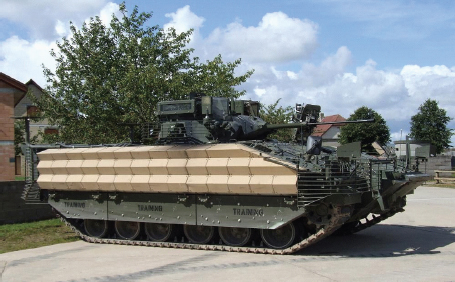
FIGURE 4-1 A warrior vehicle with added reactive appliqué and bar-armor. SOURCE: BAE Systems, U.S. Combat Systems, “Lightweighting in Military Vehicles,” presentation to the committee, December 8, 2010.
armed infantry combat vehicles of the Soviets.3 They have also been used on the FV 510 Warrior Infantry Section Vehicle, built in the United Kingdom. The latter was constructed of an aluminum alloy hull and equipped with additional appliqué armor as well as explosive-reactive armor and bar armor (Figure 4-1). The efficacy of the protection system against small arms, missiles, rocket propelled grenades, and anti-tank mines was proven during the United Nations operations in Bosnia.4
Despite the performance enhancements obtained from the use of aluminum alloys in structural components of ground vehicles, their use in armor systems for tactical vehicles has met with mixed success.5 The difficulty of using aluminum alloys in armor can be attributed at least in part to an inadequate understanding of the ballistic and blast properties of these alloys over the pertinent threat range. The ballistic properties are better understood than blast properties; however, the modeling of both types of threats is insufficient for the predictive modeling and systems-level design for performance across the full spectrum of current threats from improvised explosive devices (IEDs), explosively formed projectiles (EFPs), and other sources.
Recent aluminum-alloy developments have led to further improvements in ballistic resistance and durability. For instance, Al 2519-T87 (MIL-DTL-46192) exhibits better performance against fragmentation threats than Al 5083, with nearly the same performance against ball and armor piercing threats as Al 7039, coupled with good corrosion resistance. The first production utilization of this alloy will be the Marine Corps Expeditionary Fighting Vehicle.6
________________
3 For information on BMP-3 specifications, see http://www.army-technology.com/projects/bmp-3/specs.html and http://www.army-technology.com/projects/bmp-3/, last accessed October 19, 2011.
4 Christopher Foss and Peter Sarson. 1994. Warrior Tank Specifications: Warrior Mechanised Combat Vehicle 1987-1994. New Vanguard Series No. 10. London: Osprey. Available at http://www.army-technology.com/projects/warrior/.
5 Much of the information on lightweighting armor systems for land vehicles using materials other than aluminum is either restricted or classified and therefore is not included in this report.
6 “Army Materials Research: Transforming Land Combat Through New Technologies.” AMPTIAC [Advanced Materials and Process Technol ogy Information Analysis Center] Quarterly, Vol. 8, No. 4, 2004. Available at http://ammtiac.alionscience.com/pdf/AMPQ8_4.pdf.
Present Status
The Army has not fielded any new major combat platforms for over 20 years. Some of its early lightweighting successes still see combat. Section 4.5, which describes examples of lightweighting vehicle systems, begins with three such successes: the M113 Armored Personnel Carrier, the M551 Sheridan Light Tank, and the Bradley Fighting Vehicle.
That does not mean that the Army no longer has interest in lightweighting. On the contrary, over the past two decades it has launched five separate programs that prominently featured lightweight designs—none of which has reached production and integration into the battlefield. The difficulties facing these programs offer lessons for future lightweighting efforts. Two of these canceled programs are described in Section 4.5: the XM2001 Crusader 155mm Self-Propelled Howitzer and the Future Combat System.
4.1.3 Current State of Metrics
Unlike the aircraft industry, where the metrics for lightweighting are well established and feature prominently in the earliest stages of the design process, a comparable set of quantitative metrics appears not to exist in the ground vehicle community. Designs are usually constrained by overall vehicle weight, typically set to meet air transportability requirements. Weight savings that may be achieved through use of low-density materials or clever lightweighting designs are parlayed into weight additions elsewhere in the vehicle, to enhance functionality, e.g., increased protection against evolving threats, such as those encountered in Iraq and Afghanistan. Hence there does not appear to be a well-defined or overarching metric that characterizes “the value of a pound saved.”
In some respects, lightweighting may appear to be antithetical to the goal of warfighter protection. Historically, the level at which vehicle requirements—protection and otherwise—have been met correlates strongly with overall vehicle weight. That is, heavier classes of combat vehicles generally meet more requirements and to a higher degree than those in the lower weight classes (Figure 4-2). But these improvements invariably come at the
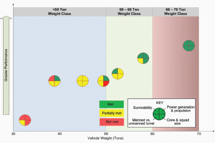
FIGURE 4-2 Tradeoffs between combat vehicle weight and achievement of performance requirements. SOURCE: Adapted from BAE Systems, U.S. Combat Systems, “Lightweighting in Military Vehicles,” presentation to the committee, December 8, 2010.
expense of reduced fuel economy, mobility, and speed. The broad trend (especially with respect to survivability) reflects to some extent the additional armor afforded to heavier vehicles. In principle, lightweighting could have beneficial effects on these attributes without necessarily compromising protection. As noted in Chapter 1, lightweighting can help to balance the “iron triangle” of performance, protection, and payload.
The challenge stems from the fact that, for a prescribed dynamic load (from a buried mine explosion, for example), the acceleration of the vehicle scales inversely with its mass. This, in turn, has important implications in the potential threat to the vehicle occupants. Clearly, this is a feature that does not derive benefit from lightweighting. Thus, lightweighting might in some circumstances be viewed as a strategy for reducing weight in one component in order to increase survivability by adding weight to a different component.
4.2 BARRIERS AND KEYS TO SUCCESS
4.2.1 Technological Challenges
Materials
Achieving protection goals while holding down costs is a continual challenge. In armor systems, significant weight reductions can be achieved through the replacement of armor steels with advanced aluminum alloys, composites, ceramics, and expanded steel. But the weight reductions come at the expense of higher cost (for examples, see Figure 4-3). In principle, even greater reductions could be achieved through the use of detection avoidance technologies and active protection systems.
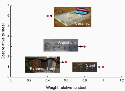
FIGURE 4-3 Tradeoffs between weight reduction and cost for some candidate materials systems used in armor systems. SOURCE: Adapted from BAE Systems, U.S. Combat Systems, “Lightweighting in Military Vehicles,” presentation to the committee, December 8, 2010.
Other structural materials, notably magnesium and titanium alloys, offer large potential advantages over steels, including higher specific strength, absence of low-temperature embrittlement, and greater structural rigidity resulting from thicker sections. Titanium also exhibits superior corrosion resistance in most service environments, yet the utilization of these materials remains rare. Numerous barriers exist to their exploitation. Chief among them are cost and domestic availability:
- The cost of extraction of raw titanium is inherently high. The current price of titanium in ingot form is approximately $20/lb. Steels, in contrast, cost between $0.50 and $3.00/lb depending on alloy and product form. Magnesium is significantly cheaper than titanium, with a current price of approximately $2/lb. For land structures, most applications of titanium and magnesium would be in the form of sheet and plate. The complexity of forming titanium and magnesium alloys into useful engineering shapes coupled with their low production volumes exacerbate the price differentials with the baseline steels.7
- Domestic availability and sheet/plate manufacturing capacity of magnesium and titanium alloys are far below the large-tonnage requirements of targeted land-based military vehicle applications.
Additional (secondary) considerations include the following:
- Welding is the most economical way to join materials in producing large structures with good mechanical integrity. It is also the principal route for producing water-tight structures (e.g. amphibious vehicles). The weldability of titanium and magnesium alloys remains problematic in routine industrial practice in land-based vehicles.
- Monolithic aluminum, magnesium, and titanium alloys exhibit inferior spall resistance relative to steels.8 They may also exhibit inferior service lives due to lower fatigue resistance as well as susceptibility to corrosion in marine environments.
- There is an understandable reluctance within the DOD and its suppliers to transition to new materials that are not supported by comparable levels of experience in manufacturing, assessment of battlefield damage, and in-field repair.
New Designs
Some intriguing new designs for vehicles are emerging that offer promise for greater protection without adding more armor weight. One approach for military trucks is to “vent” the dynamic load (explosive force) up through a channel in the vehicle as if through a chimney to reduce the coupling of the blast loading to the vehicle.9 As reported in the New York Times, “if the final tests go well, the invention could save billions in new vehicle costs and restore much of the maneuverability that the Army and the Marines have lacked in the rugged terrain in Afghanistan, military officials say.”10
Another approach is to adapt the V-hull design used in mine-resistant trucks into a double V-hull for the Army’s Stryker Brigade Combat Vehicle. The recent award of a contract to build 450 double V-hull Stryker vehicles comes in response to the need to counter the increasingly deadly threats experienced in Afghanistan from roadside
________________
7 For more information on forming titanium and magnesium alloys, see http://www.metalprices.com/FreeSite/metals/ti/ti.asp and http://www.metalprices.com/freesite/metals/Steel/Steel.asp. Last accessed October 19, 2011.
8 BAE Systems, U.S. Combat Systems, “Lightweighting in Military Vehicles,” presentation to the committee, 2010; and “Army Materials Research: Transforming Land Combat Through New Technologies,” AMPTIAC [Advanced Materials and Process Technology Information Analysis Center] Quarterly, Vol. 8, No. 4, 2004, available at http://ammtiac.alionscience.com/pdf/AMPQ8_4.pdf.
9 Grace V. Jean. 2011. “Double V-Hulls, Chimneys, Seen as Viable Alternatives to Armor.” National Defense. March. Available at http://www.nationaldefensemagazine.org/archive/2011/March/Pages/DoubleVHullsChimneysSeenAsViableAlternativestoArmor.aspx.
10 Christopher Drew. 2011. “Revamped Humvee Draws Military’s Eye.” New York Times. July 22. P. B1. Available at http://www.nytimes.com/2011/07/23/business/humvee-with-chimney-for-safety-draws-militarys-interest.html. Last accessed October 19, 2011.
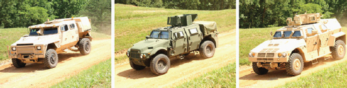
FIGURE 4-4 Three joint light tactical vehicle prototypes. SOURCE: S. Magnuson. 2010. “New Truck to Show the Way for Acquisition Reforms.” National Defense Magazine. August.
bombs.11 Improved vehicle survivability in this evolving production and upgrading of vehicles will be accomplished by added armor and alterations in design approaches.12
4.2.2 Reducing the Acquisition Cycle
The technological challenges are exacerbated by a protracted acquisition process during which the vehicle requirements often “creep.” That is, various DoD agents sequentially add requirements from the time of initial design to that of vehicle production and delivery. Without knowledge of the full spectrum of expected requirements of the vehicles at the outset, defense contractors are naturally disinclined to replace existing materials with new ones. The risk is that deficiencies in material performance may not emerge until late in the design and manufacturing stages, wherein the full spectrum of requirements becomes known.
Attempts at accelerating the process through competitive prototyping—a process in which two or more defense contractors produce competing prototypes—have met with mixed success.13 Its underlying rationale is that forcing the manufacturers to use proven technologies will discourage the later introduction of new and untested components; as a result, competitive prototyping is expected to reduce the risk of cost overruns and failure for military hardware development programs. It has been adopted as a mandatory requirement in DOD Instruction 5000.2, updated in December 2008.
In a recent example of competitive prototyping, three vendors—BAE Systems, Lockheed Martin, and a consortium of AM General and General Dynamics Land Systems—produced a total of 21 prototypes (Figure 4-4) for the Joint Light Tactical Vehicle (JLTV) program, which is intended to replace some Humvees (HMMWVs—High-Mobility Multipurpose Wheeled Vehicles). Testing of these prototypes began in August 2010. The initial promise of this endeavor faded, as Mark McCoy, the Army’s JLTV product manager, reported in February 2011 that every prototype design was between a few hundred and 1,000 lb too heavy to be airlifted by a CH-47 Chinook helicopter.14
The JLTV was intended to meet the needs of the Army, which placed greater emphasis on protection, and the Marine Corps, which gave higher priority to lightweighting. Attempting to satisfy both sets of requirements simultaneously is likely the reason that the 21 JLTV prototypes failed to meet weight specifications, resulting in
________________
11 Grace V. Jean. 2011. “Double V-Hulls, Chimneys, Seen as Viable Alternatives to Armor.” National Defense. March. Available at http://www.nationaldefensemagazine.org/archive/2011/March/Pages/DoubleVHullsChimneysSeenAsViableAlternativestoArmor.aspx.
12 Christopher Drew. 2011. “Revamped Humvee Draws Military’s Eye.” New York Times. July 22. P. B1. Available at http://www.nytimes.com/2011/07/23/business/humvee-with-chimney-for-safety-draws-militarys-interest.html. Last accessed October 19, 2011.
13 This section draws on S. Magnuson, 2010, “New Truck to Show the Way for Acquisition Reforms,” National Defense Magazine, August, available at http://www.fas.org/sgp/crs/natsec/RL34026.pdf; and E. Beidel, 2011, “Challenges Remain as JLTV Competition Heats Up,” Na tional Defense Magazine, May.
14 Reported at the National Defense Industrial Association’s Tactical Wheeled Vehicle conference, February 2011, and reported in E. Beidel, 2011, “Challenges Remain as JLTV Competition Heats Up,” National Defense Magazine, May.
a delay in finding a satisfactory “trade” between protection and weight-related performance characteristics for light tactical wheeled vehicles.
The JLTV prototype experience suggests the desirability of finding ways to increase the probability that prototypes will meet requirements. For example, instead of discovering during prototyping how new materials and new designs for lightweighting affect other attributes, it would improve the chances of detecting and addressing problems to test new technologies earlier in the acquisition process. For example, perhaps a precursor demonstration step could try out new materials and new designs for lightweighting in terms of their effects on other attributes before a prototype is developed.
The Weapons System Acquisition Reform Act of 2009 requires that competitive prototypes be produced for major weapons acquisition programs prior to Milestone B, which is when independent review boards decide whether the program can proceed to the engineering and manufacturing development (EMD) phase.15 Under some circumstances competitive prototyping may be waived, in which case only one prototype is required. Nonetheless, it appears that the Army has been able to waive even the single prototype requirement prior to EMD as evidenced by JLTV program. Specifically, a recent JLTV vehicle update stated:
The Government has made a determination to NOT require the delivery of a demonstrator vehicle during the EMD RFP proposal phase. Due to evolving EMD requirements, it is assumed that any demonstrator vehicle built to currently available draft RFP requirements will not be reflective of the final RFP requirements for EMD.16
The Army’s decision is based on the expectation that the requirements will change, but it has the added benefit of providing more time to validate the technology before building a prototype.17
4.3 LIGHTWEIGHTING OPPORTUNITIES FOR LAND-BASED VEHICLES
Lightweighting of land-based vehicles remains a clear strategic focus of the DoD.18 Indeed, with the escalation in “scope growth and requirements creep”—that is, the expansion of the requirements of a single vehicle in order to meet a multitude of mission types and increased operational performance, such as increased warfighter protection, increased vehicle range, and reduced energy utilization, while minimizing development and production costs of multiple vehicle variants—the need for lightweighting is arguably more acute than ever.
Numerous opportunities exist to improve tactical utility of future military vehicles through lightweighting. Bringing them to fruition will require long-term commitments and coordinated multi-agency strategies. Specific opportunities and strategies for their successful implementation follow.
4.3.1 Systems Engineering
As described in Chapter 2 (Air), systems engineering is a strategy for considering the many elements of a complex system early in the design and acquisition of that system. Bringing together experts knowledgeable about diverse aspects of the system—components, design, manufacturing, performance, cost, etc.—the risk of discovering
________________
15 Weapon Systems Acquisition Reform Act of 2009, 111th Congress, S. 454, Sec. 203, available at http://www.gpo.gov/fdsys/pkg/BILLS-111s454enr/pdf/BILLS-111s454enr.pdf.
16 For more information on the Joint Light Tactical Vehicle (JLTV) EMD Phase, see http://contracting.tacom.army.mil/majorsys/jltv_emd/jltv_emd.htm, last accessed September 28, 2011.
17 While considering next steps for the JLTV, the Army is also pursuing the Humvee Recap, intended to add protection to the Humvee while maintaining or reducing weight. See Grace V. Jean, “Humvee Recap Competition Heating Up,” National Defense, October 2011, available at http://www.nationaldefensemagazine.org/archive/2011/October/Pages/HumveeRecapCompetitionHeatingUp.aspx. It was beyond the commit tee’s scope to address the choices among lightweight tactical land vehicles; the JLTV is described to illustrate competitive prototyping and the difficulty of meeting different needs simultaneously.
18 NRC. 2003. Use of Lightweight Materials in 21st Century Army Trucks. Washington, D.C.: The National Academies Press. Available at http://www.nap.edu/catalog.php?record_id=10662. Last accessed October 19, 2011.
deficiencies later in the process is reduced. Within the Army, TARDEC takes the lead on systems engineering for ground vehicles.19 The last example in Section 4.5 is the successful use of systems engineering in the Ford F-150.
4.3.2 Virtual Prototyping
The computing power available to the DOD is tremendous. It should enable increased use of virtual prototyping and increased emphasis on system design, in part to allow early assessment of the tradeoffs in lightweighting strategies. This goal will require integration of shared models of materials, processes and performance between vendors and original equipment manufacturers (OEMs). Virtual prototyping would also have the desirable effect of compressing the acquisition cycle.
As suggested under “Competitive Prototyping,” ways of increasing the probability that prototypes will meet requirements may be available. Virtual prototyping could play an important role in assessing new materials and new designs for lightweighting in terms of their effects on other attributes. The design solutions that look the most favorable could then progress to the physical prototyping stage.
4.3.3 New Computational Tools
The success of virtual prototyping and system design is predicated on the availability and use of high-fidelity computational tools for describing the loads imparted by specific enemy threats, e.g., kinetic energy penetrators, shaped charges, EFPs, and IEDs, as well as the response of materials and structures under those loads. Although significant progress has been made on this front over the past decade, striking deficiencies are evident and require remediation. Specifically, there is a need to develop a better understanding of the physics and mechanics of plastic flow, damage evolution and material rupture under extreme dynamic environments. Effects of microstructural heterogeneities in single- and multiphase systems, processing history and probabilistics need to be considered as well. Additionally, codes that integrate multi-physics phenomena and multiple length scales are required. There are also deficiencies in commercial finite element codes in accurately capturing the coupling between dynamic loads and structural response. The opportunities for potentially fruitful research areas include extended finite element codes, particle-based numerical methods, and adaptive physics models.
4.3.4 Lightweight Materials
A number of relatively lightweight materials such as titanium, magnesium, and structural composites show outstanding potential for lightweighting and for expanding the capabilities of military vehicles. But in many instances the implementation of these materials is hampered by their high costs, low technology or manufacturing readiness levels, and limited domestic availability. Capitalization of these opportunities will require a federal investment strategy to identify the materials that are of greatest strategic value to the DOD, seek lower-cost production routes, and increase the domestic processing capacity and manufacturing readiness levels.
One way to facilitate the introduction of lightweight materials is through increased utilization of the same materials in industrial sectors such as transportation, aerospace, energy security, and power generation. For example, the materials requirements for heavy wheeled equipment and trucks have many potential parallels with land-based military vehicles. In this context, it is important to note that the National Automotive Center (NAC) at TARDEC has the mission to identify and develop dual-use technologies for land-based vehicles between DOD and the automotive industry.
Recent advances in the synthesis of titanium alloy powders by direct reduction methods (meltless titanium) have led to new opportunities to produce titanium alloys with enhanced capabilities at lower cost.20
________________
19 John Wray. 2010. “’Insight, Not Just Oversight’—Following DOD Lead, Embedded Systems Engineering Provides the Framework for Solid Decision.” Accelerate magazine, Summer, p. 10. Available at http://tardec.army.mil/Documents/TARDEC_0910_accelerate_Summer_2010.pdf.
20 A. Woodfield, E. Ott, J. Blank, M. Peretti, D. Linger, and L. Duke. 2009. “Meltless Titanium—A New Light Metals Industry.” Materials Science Forum, Vols. 618-619, pp. 135-138.
4.3.5 Standardization in Vehicle Design
The success of military vehicles is predicated on the alignment of their capabilities with mission requirements. The recent historical experience has been that enemy threats and the associated mission requirements have evolved more rapidly than the corresponding capabilities, especially with regard to protection systems. This disparity requires not only close scrutiny of the threats that are likely to be faced in the future (a challenging task that is undoubtedly being tackled by the DOD) but also emphasis on the adaptability of fielded systems to meet the evolving threats. Commonality and standardization in vehicle design may help to improve in-theater upgrading, facilitate repair, and reduce costs and acquisition times.
4.3.6 Other Emerging Technologies
Among the emerging structural concepts for lightweighting, high-strength “expanded steel” for use in armor systems shows promise. Concepts that enable multi-functionality, e.g., by combining structural functionality with personnel and cargo protection, are also worth pursuing.
It would appear that there are also opportunities for very significant reductions in the weight of protection systems through emerging detection avoidance and active protection technologies. Identifying revolutionary or game-changing strategies to protection could reduce the needed armor, with major lightweighting benefits..experience of the Future Combat System (see Section 4.5.5) might offer some lessons.
Development and use of materials and design tools for lightweighting of land-based military vehicles will be a source of information and tools for the automotive industry, which has been striving to reduce the weight of vehicles without compromising other attributes that consumers value.
4.4 LONG-TERM CONCERNS IN LIGHTWEIGHTING LAND-BASED VEHICLES
A National Research Council report,21 written and released in 2003, concluded that cost was the principal factor driving the design of Army vehicles. Almost immediately thereafter, the start of the U.S. conflicts in Afghanistan and Iraq meant that U.S. troops were actively engaged in combat. The current view from all levels within the DoD appears to be that, with troops presently in combat and considering the heavy casualties incurred over the past 8 years, protection is the preeminent driver of vehicle design. It would not be unexpected, however, to see the pendulum swing back—wherein greater focus is directed at cost rather than principally protection—once active conflicts have ended and the immediate risks to warfighters have seemingly dissipated. Balancing these competing drivers of design in a changing environment is a never-ending issue.
Implementation of lightweighting strategies will require a multi-pronged approach involving not only scientific discovery and technology development but also coordinated federal strategies and policies. Perhaps the largest barrier stems from the broad perception that the fields of structural materials and manufacturing are sufficiently mature so as to warrant only minimal research support and development. Indeed, the past two decades have seen a dramatic decline in funding in these areas. It seems likely that further progress in lightweight structural materials and their associated manufacturing processes will be incremental and slow.
________________
21 NRC. 2003. Use of Lightweight Materials in 21st Century Army Trucks. Washington, D.C.: The National Academies Press. Available at http://www.nap.edu/catalog.php?record_id=10662.
4.5 EXAMPLES OF LIGHTWEIGHTING IN LAND-BASED VEHICLES
4.5.1 M113 Armored Personnel Carrier
The M113 Armored Personnel Carrier (APC)22 was introduced in 1960 to transport infantry forces across a hostile battlefield. Lightweighting helped the M113 APC revolutionize mobile military operations; it was air-transportable, air-droppable, and capable of amphibious operation in lakes and streams, cross-country travel over rough terrain, and high-speed travel on pavement. These features allowed the M113 to be deployed in a wide range of combat situations and rapid-deployment scenarios.
M113: Lightweighting When
Survivability Is Primary
The many variants in the M113 family of vehicles illustrate that effective lightweighting can be used to retain performance characteristics while improving survivability.
The U.S. Army was the first service to use aluminum as an armor material in armored transport vehicles and offensive weapon vehicles. The original M113 was built of aircraft-quality23 Aluminum 5083—an alloy that possesses strength approaching those of some steels at only about one-third the weight. The hull armor was also made from Aluminum 5083.
The M113 has been remarkably successful; about 80,000 M113-based systems have entered service in more than 50 countries. It became the basis for a family of vehicles produced in about 40 variants, with many times that number of minor field modifications. With updating and reconfiguring, M113s are still being produced and fielded today.
The M113 was conceived as a “battle taxi” that would carry infantry to the battlefield, where they would fight on foot. Early in the Vietnam War, this approach resulted in high casualties for the Army of the Republic of Vietnam (ARVN), as they dismounted into knee-deep water where they were vulnerable to enemy fire. Thereafter, the ARVN ignored U.S. doctrine and remained inside the M113. While the Aluminum 5083 armor in the M113 stopped small arms bullets and shell fragments, it did not stop rocket-propelled grenades or provide adequate protection against mine blasts detonated under the vehicle. In 1965, the ARVN modified the M113 by expanding from one exposed machine gun to three machine guns, all protected by armor; this version was the first armored cavalry assault vehicle (ACAV). Starting in 1966, an improved version of the ACAV was deployed in Vietnam by U.S. troops, with further upgrades during the war (Figure 4-5).
A major redesign came in 1987, with the introduction of the A3 version. Spall suppression liners throughout the interior of these vehicles offer greater troop protection by restricting the spread of spall when a round penetrates the hull. A new powertrain provides greater mobility and survivability, while improving fuel efficiency, acceleration, speed, and braking.
The upgrades have increased the weight—the combat weight of the 1960 M113 was 23,520 lb, compared with 27,200 lb for the A3. As a result, the A3 was given a more powerful engine, which offered the ability to add hardened steel side armor, a “slat armor” cage, and additional anti-mine armor on the vehicle underbelly. Although the armor increases the weight to 31,000 lb, the use of lightweighting techniques has made it possible for the A3 to have the desired performance and survivability attributes.
While the U.S. Army returned to the single machine gun M113 after the Vietnam War, the Israeli Defense Force (IDF) embraced the idea of the ACAV and still uses it today. Its version is protected by a “skirt” of lightweight sheets of perforated steel, which reduces damage by detonating rocket-propelled grenades before they come into contact with the hull. The IDF tried a variant with explosive reactive armor, but the added weight strained the
________________
22 The description of the M113 draws on D. Starry, 1978, “Mounted Combat in Vietnam,” Vietnam Studies, CMH Pub 90-17, Department of the Army; S. Dunstan, 1983, The M113 Series, London: Osprey; S. Crist, 2004, “M113 APC: Four Decades of Service and Still Showing Potential,” Infantry Magazine, July-August, available at http://findarticles.com/p/articles/mi_m0IAV/is_4_93/ai_n6362165/; http://www.fas.org/man/dod-101/sys/land/m113.htm; and http://www.army.mil/factfiles/equipment/tracked/m113.html, accessed June 10, 2011.
23 The development and qualification of aluminum alloys did not progress as quickly for use in land vehicles as for use in aerospace applications.
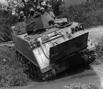
FIGURE 4-5 M113 armored cavalry assault vehicle in Vietnam. SOURCE: Available at http://en.wikipedia.org/wiki/File:Armored_cavalry_assault_vehicle.jpg.
engine and reduced speed and handling; this variant was discontinued. The IDF is now working on a lightweight but stronger armor made of layers of steel, rubber, ceramics, and explosive reactive armor.
4.5.2 M551 Sheridan Light Tank
The M551 Sheridan Light Tank,24 shown in Figure 4-6, was an assault vehicle designed in the early 1960s to have both air-drop and swimming capabilities. It saw extensive combat in Vietnam and limited service in Operation Just Cause (in Panama) and Operation Desert Storm (in Kuwait).
M551: Improved Performance,
Decreased Survivability
The M551 illustrates the mixed success experienced in replacing steels with aluminum alloys in military vehicles for which survivability and performance are both important. The specific approaches to lightweighting the M551 created vulnerabilities.
The Sheridan Tank was armed with a technically advanced gun that fired conventional ammunition and guided anti-tank missiles. With an aluminum hull and the first use of spaced aluminum armor, it was at the time a unique approach to lightweighting. Equipped with a relatively powerful 300 hp diesel engine, the M551 was exceptionally fast. It was airdrop-capable and fully amphibious, but these advantages of light weight came at a cost.
In its first combat mission, the Sheridan drove over a mine, which ruptured its hull and then ignited the ammunition of the main gun, causing an explosion that destroyed the tank. The aluminum armor could be pierced not just by under-belly mines but also by heavy
________________
24 The description of the M113 is based on D. Starry, 1978, “Mounted Combat in Vietnam,” CMH Pub 90-17, Vietnam Studies, Department of the Army; R.P. Hunnicutt, 1995, Sheridan: A History of the American Light Tank, Vol. 2, Presidio Press; and http://www.army-guide.com/eng/product3393.html.
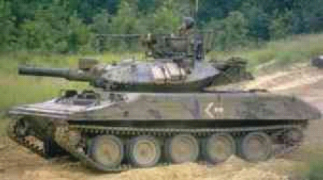
FIGURE 4-6 M551 Sheridan tank. SOURCE: BAE Systems, U.S. Combat Systems, “Lightweighting in Military Vehicles,” presentation to the committee, December 8, 2010.
machine-gun rounds as well. Its 152mm gun was too big for the lightweight chassis, causing the entire vehicle to recoil with great force when the gun was fired. Field commanders commonly added a large steel shield around the gun for protection while firing it. The Sheridan was good at opening bamboo thickets, but not at breaking through dense jungle. Thus, although the Sheridan had greater mobility, firepower, range, and night-fighting ability than its predecessor, its deficiencies led to heavy Sheridan losses in Vietnam and Cambodia.
The Army began to phase out the Sheridan in 1978; however, the 82nd Airborne Division retained its until 1996 because the Sheridan was the only air-deployable tank in its inventory. The Sheridan tanks were upgraded with a thermal sighting system and were used successfully in Operation Just Cause and Desert Storm.
4.5.3 Bradley Fighting Vehicle
The Bradley Fighting Vehicle25 was originally designed as an APC and a tank-killer. Its main task was transporting infantry with armor protection while providing covering fire to pin down enemy troops. The new Bradley was designed to keep up in formation with M1 Abrams battle tank. This allowed the two vehicles to maintain formations while moving, something that the older M113 could not do as it had been designed to complement the M60 Patton.
Bradley: Benefits of Various
Aluminum Alloys
Experience with different aluminum alloys on the Bradley Fighting Vehicle has provided knowledge that can be applied to future vehicles.
The Bradley, shown in Figure 4-7, had a hull base made from Al 5083-H131 (MIL-DTL-46027), and the upper half of the vehicle employed Al 7039-T64 (MIL-DTL-46063). In service, the 7039 alloy has been found to exhibit better performance against ball and armor piercing (AP) threats than 5083 but with
________________
25 This case study is based on W.B. Haworth, 1999, The Bradley and How It Got That Way: Technology, Institutions, and the Problem of Mechanized Infantry in the United States Army, Westport, Conn.: Greenwood Press; “Army Materials Research: Transforming Land Combat Through New Technologies,” AMPTIAC [Advanced Materials and Process Technology Information Analysis Center] Quarterly, Vol. 8, No. 4, 2004, available at http://ammtiac.alionscience.com/pdf/AMPQ8_4.pdf; and NRI, http://www.army-technology.com/projects/bradley.
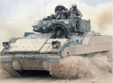
FIGURE 4-7 Bradley Fighting Vehicle. SOURCE: Available at http://osd.dtic.mil/photos/Nov2004/041030-F-2034C-040.html.
some loss in performance against fragmentation threats. However, 7039 has been found to be more susceptible to stress-corrosion cracking, especially in the short-transverse direction.
Combat survivability concerns were raised about the Bradley because it used aluminum armor, and ammunition is stored in the middle of the vehicle, but the Bradley has not experienced many losses. To improve survivability and armor protection designers added spaced laminate belts and high-hardness steel skirts to later versions. These additions increased overall weight by about 10 percent, to 33 tons, while decreasing the Bradley’s mobility. Later versions of the Bradley and Abrams were designed to carry reactive armor26 to protect against RPGs. This armor was employed in Iraq and proved effective in increasing survivability. In 2009, the Army awarded a contract to add armor to protect against improvised explosive devices (IEDs), as well as other enhancements of warrior protection.
4.5.4 Crusader 155mm Self-Propelled Howitzer27
The Crusader 155mm artillery system (shown in Figure 4-8) was intended to be the Army’s next- generation self-propelled (SP) howitzer, replacing the M109A6 Paladin SP Howitzer and the M992 Field Artillery Ammunition Support Vehicle. It was initiated in 1994 to provide enhanced survivability, lethality, and mobility and therefore be more readily deployable than the platforms it replaced. In 2000, after a 60-ton developmental platform was produced, the Army restructured the program to meet the new weight requirement of 40 tons. This lower weight would allow two vehicles to be transported into theater on a C-5 or C-17 aircraft, reflecting the Army’s planned transformation to a lighter, more deployable future force. The schedule called for DoD to decide in April 2003 whether the Crusader should enter development and demonstration; assuming they continued the program, production of an anticipated 1,100+ vehicles (later reduced to 480) was to begin in 2008.
________________
26 From Jargon Database.com: “Reactive armor involves explosive devices attached to armored vehicles that explode before an incoming projectile strikes the vehicle. The ensuing outward explosion deflects or minimizes the inward momentum of the oncoming projectile.” Avail able at http://www.jargondatabase.com/Category/Military/Army-Jargon/Reactive-Armor.
27 This section draws on Government Accountability Office, 2002, “Defense Acquisitions: Steps to Improve the Crusader Program’s Invest ment Decisions, February, available at http://www.gao.gov/new.items/d02201.pdf; and GAO, 2001, “Defense Acquisitions: Army Transforma tion Faces Weapon Systems Challenges, May, available at http://www.gao.gov/new.items/d01311.pdf.
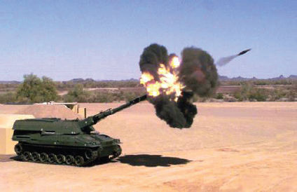
FIGURE 4-8 Crusader 155mm self-propelled howitzer. SOURCE: Available at http://www.pica.army.mil/voice2002/020517/4_11_00%20Zone%206-1.jpg.
Crusader: Importance of a Broad
Set of Goals for Lightweighting
Lightweighting primarily for transportability proved not to be a compelling reason to continue building a new system that was not sufficiently more capable than its upgraded predecessor—nor sufficiently ahead of its planned successor. Changing requirements, as a result of the end of the Cold War, added to costs and schedule.
In May 2002, Secretary Rumsfeld cancelled the $11 billion dollar Crusader program because it was deemed neither mobile enough nor precise enough. A GAO report determined that the improvement in transportability was not significant—two complete systems with supporting equipment would need four flights instead of five. More importantly, that report found that the majority of critical technologies were not sufficiently mature and that the Crusader’s schedule had considerable overlap with the Future Combat System (see Section 4.5.5), which was intended to replace it. With upgrades, the existing fielded Paladin possessed sufficiently advanced performance characteristics to make it still an effective weapon in the land-based vehicle category to meet Army needs.
In the context of the lightweighting focus of this report, the desired C-17 transportability featured significantly in the design requirements central to the 155mm Crusader but did not take into account the transport of the supporting equipment. A 20 percent reduction in C-17 flights was not sufficient to make up for the immaturity of critical technologies and the rising costs.
4.5.5 Future Combat System (FCS) Combat Vehicles28
The Future Combat Systems (FCS) program was remarkably ambitious: a family of 14 high-tech manned and unmanned combat vehicles, encompassing robots and an array of sensors, connected in a single battle command-
________________
28 This section is based on Andrew Feickert and Nathan Jacob Lucas, 2009, Army Future Combat System (FCS) “SpinOuts” and Ground Combat Vehicle (GCV): Background and Issues for Congress, Congressional Research Service, November, available at http://www.fas.org/
and-control network, at a cost of $92 billion (later increased to $164 billion). The Manned Ground Vehicle component was planned to provide eight FCS variants: an infantry carrier, a command-and-control vehicle, a mounted combat system, a recon naissance and surveillance version, a non-line-of-sight cannon, a non-line-of-sight mortar, a recovery and maintenance vehicle, and a medical treatment variant.
FCS: Too Ambitious for
Available Technology
The Future Combat System was a complex program with ambitious goals, including a lightweight-ing goal of building a combat vehicle with only one- quarter of the weight of the Abrams tank but similar speed and survivability. These goals depended on several technologies that required much additional development before they could be inserted in the combat vehicles. When development did not occur quickly enough for the FCS schedules, there were cost increases and delays.
The FCS was introduced in 1999 as the major research, development, and acquisition program intended to lead to the Army’s transformation. Key requirements were C-130 transportability and an associated fully loaded weight of 30 tons. It was to be as durable and to offer as much protection as an Abrams Battle Tank, at only 25 percent of the weight. The weight requirement to allow C-130 transportability was considered crucial for landing in remote areas with, at best, primitive runways.
The drive to lightweighting of the FCS concepts included an effort to significantly lower fuel costs, which entailed a radical change in technology. Instead of a gas-diesel powered engines, as used in the Prius, the FCS called for development of the much less mature technology for diesel-electric hybrid engines. Another of the lightweighting strategies was to use new technologies for “active” defensive systems that have the capability to shoot down incoming threats such as RPGs, thus needing less heavy armor than the Abrams, which focuses on frontal attack survivability.
The Army treated its weight requirements as firm throughout much of the early tenure of the FCS program. Thus, when the concepts submitted by the two prime contractors for the main vehicle were overweight, the Army considered stripping some components to transport on a second aircraft, requiring additional logistical support to reassemble the vehicle in theater. However, in 2005 the Army removed the C-130 transportability requirement and substituted the stipulation that three FCS vehicles must fit in a C-17 heavy lift transport aircraft, thereby allowing the FCS vehicle weight to increase from 18 to 25 tons.29
During 2003-2009, the program underwent several rounds of restructuring. In April 2009, Secretary Gates recommended cancellation of the FCS Manned Ground Vehicle program. Secretary Gates and other critics gave several reasons for the demise of the FCS program, included its high cost and declining relevance for expected future defense needs. A chief listed cause is the reliance of FCS on technologies not yet mature; i.e., the technology readiness levels (TRLs) were too low, particularly for the high-tech “active” protection systems. In 2006, the GAO found that “none of FCS’s 49 critical technologies was at a level of maturity recommended by DoD policy at the start of a program.”30 In 2008, GAO described the FCS as “about halfway through its development phase, yet it is, in many respects, a program closer to the beginning of development.”31 It was the need to bring a large number of needed technologies to maturity that led to cost increases, delays, and ultimately cancellation.
________________
sgp/crs/weapons/RL32888.pdf; Sandra I. Erwin, 2009, “Uphill Battle: Army’s Next Combat Vehicle: New Beginning or FCS Sequel?,” National Defense, August 1, available at http://www.highbeam.com/doc/1G1-205905726.html; Sandra I. Erwin, 2005, “Army Struggles with Weight of Future Combat Systems,” National Defense, April, available at http://www.nationaldefensemagazine.org/archive/2005/April/Pages/UF-Army_Struggles5799.aspx; Sandra I. Irwin, 2005, “For Army’s Future Combat Vehicles, Flying by C-130 No Longer Required,” National Defense, November, available at http://www.nationaldefensemagazine.org/archive/2005/November/Pages/UF-For_Army5525.aspx.; and http://www.globalsecurity.org/military/systems/ground/fcs.htm.
29 Sandra Erwin. 2005. “For Army’s Future Combat Vehicles, Flying by C-130 No Longer Required.” National Defense. November.
30 GAO. 2006. “Defense Acquisitions: Improved Business Case Is Needed for Future Combat System’s Successful Outcome.” GAO-06-367. Available at http://www.gao.gov/new.items/d06367.pdf.
31 GAO. 2008. “Defense Acquisitions: 2009 Review of Future Combat System Is Critical to Program’s Direction, Statement of Paul L. Francis, Director Acquisition and Sourcing Management.” GAO-08-638T. April. Available at http://www.gao.gov/new.items/d08638t.pdf.
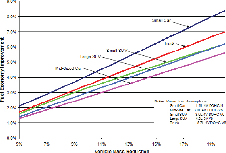
FIGURE 4-9 Impact of weight on fuel economy for personal vehicles. SOURCE: Bruno Barthelemy, Ford Motor Company, “Lightweight Technologies,” presentation to the committee, October 2010.
4.5.6 Application of Systems Engineering to Lightweighting—Ford F-150 Example
Ford’s customers rarely care about the weight of their vehicles per se, but they do care about the vehicle’s purchase price, operating costs, gas mileage, durability, and performance. Lightweighting improves performance and gas mileage (Figure 4-9); the challenge is to obtain these benefits without sacrificing durability or crash-worthiness. To achieve the best trade among performance, weight, cost, and gas mileage for the F-150 pickup, Ford uses a sophisticated systems engineering approach that involves a gated technology readiness assessment, a conceptual design that matches load lines to topology, and maximizes unitization to meet crashworthiness and durability requirements.32
Ford: Systems Engineering
Supports Lightweightimg
It takes more than materials to achieve lightweight products. Systems engineering involves a broad group of experts so that materials, manufacturing, and assembly are all considered in the design of a system. A gated process makes sure that technologies are of sufficient maturity before they are used.
The systems engineering process brings together all elements that affect the design of the system— design, engineering, manufacturing, assembly, and materials specialists to define a concept to reduce weight without reducing crashworthiness or durability of the truck. The process is collaborative. Manufacturing brings its latest knowledge, experience, and scale-up demonstrations of hydroforming high-strength steels. Assembly brings its latest capabilities for laser welding and bonding. Together they bring their latest
________________
32 Bruno Barthelemy, Ford Motor Company, “Lightweight Technologies,” presentation to the committee, October 2010.
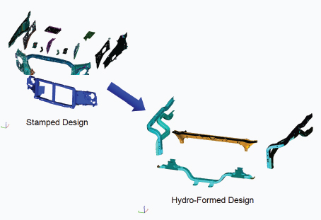
FIGURE 4-10 Improved topology offered by hydroformed substructures. SOURCE: Bruno Barthelemy, Ford Motor Company, “Lightweight Technologies,” presentation to the committee, October 2010.
demonstrations of combining hydroforming with simple laser welds to form parts with complex shapes. Materials specialists bring their most mature developments in high-strength steels since these offer thinner gauges for removing weight. The gated development process ensures that the technologies brought to the design trades have demonstrated scale-up and maturity required for application to the potential design.33
With these technologies on the table, the design team (including representatives from each technology area) can consider the forward cab section of the truck and reduce part count and simplify the design, as shown in Figure 4-10, while still meeting requirements for crashworthiness and durability. The simpler unitized design reduces welds significantly, thereby reducing cost and improving durability and stiffness. Moreover, the welds that are retained are designed to be easily applied with good access for the weld machines. In addition, the turns and twists permitted with the hydroformed substructures offer greater energy absorption for crash protection in the lighter weight structure.
All of the improvements noted above could have been achieved without significant advances in materials technology—assuming the steels were all hydroformable in the gauges required. The advanced high-strength steels offer smaller gauges to achieve higher-strengths and allow greater hydroformability as well. Consequently, the F-150 has seen a continuous improvement in weight reduction through advanced materials (Figure 4-11).
The topological design, afforded by the forming capability of the steels, provides a more modular assembly with fewer attach points, reducing assembly time and cost. The benefits to the customer are real, measurable, and result in a continuously improving product that is one of the most successful in its market.
________________
33 Roy Williamson and Jon Beasley. 2011. “Automotive Technology and Manufacturing Readiness Levels.” Automotive Council of the UK, February. Available at http://www.automotivecouncil.co.uk/wp-content/uploads/2011/02/Automotive-Technology-and-Manufacturing-Readiness-Levels.pdf.
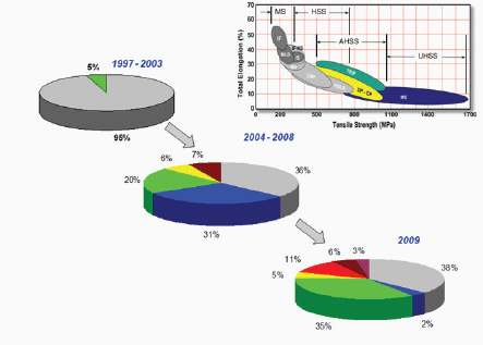
FIGURE 4-11 Continuous improvement in materials for the Ford F-150. MS, martensitic steel; HSS, high-strength steel; AHSS, advanced high-strength steel; UHSS, ultra high-strength steel. SOURCE: Bruno Barthelemy, Ford Motor Company, “Lightweight Technologies,” presentation to the committee, October 2010.
- Lightweighting of land-based vehicles has been pursued as a means to facilitate air transport capability for rapid deployment, improve fuel economy, more readily cross open-water barriers, and enhance battlefield mobility and speed.
- Using aluminum alloys as primary hull materials for protection in tactical vehicles has proven effective in meeting many vehicle requirements, including speed, maneuverability, and survivability against some threats.
- Aluminum alloy hulls have not been able to provide the desired protection against the most lethal threats. The ever-increasing level of threat from RPGs, EFPs, shaped charges, mines, and IEDs has forced “up-armoring” across the various classes of land-based combat vehicles, with a concomitant increase in weight.
- Titanium and magnesium have properties that could greatly advance lightweighting, but there are many barriers to their utilization. Titanium is very expensive to extract. Magnesium is in short supply domestically and is also more expensive to form into useful product shapes than is aluminum or steel. Before either material can be widely used in lightweighting, new manufacturing technologies are needed to improve weldability, formability, spall resistance, fatigue resistance, and (particularly for titanium) susceptibility to corrosion in marine environments.
- The requirement for competitive prototyping (or, with a waiver, for a single prototype) prior to the engineering and manufacturing development phase can, in some instances, inhibit the use of new materials and new designs by not allowing adequate time for testing and validation.
- Because of the great emphasis on soldier protection as well as the pressures to control costs, lightweighting of land-based combat vehicles has proven to be more challenging than that of air and sea vehicles. Thus, it is not surprising that, apart from aluminum-based alloys, few new materials have found their way into extensive implementation in land-based vehicles.


