
4
Technologies for Cleanup of CWM Sites
This chapter describes the current supporting technologies that might be used for the cleanup of sites containing chemical warfare materiel (CWM). To put these technologies in context, a scenario is developed for a site with known or suspected CWM.
Suspected subsurface CWM is located by geophysical technologies, typically magnetometers or active electromagnetic sensors, which are in common use for the detection of conventional munitions and explosives of concern (MEC). U.S. Army Corps of Engineers (USACE) contractors erect a containment structure over the detected anomaly and dig toward the object by mechanical or manual means, or both, that are commonly used for conventional MEC. Upon discovery of a suspected CWM, work stops in the area until military explosive ordnance disposal (EOD) technicians or Chemical Biological Radiological Nuclear (enhanced) Analysis and Remediation Activity (CARA) civilian personnel respond. EOD/CARA personnel complete the removal and evaluation of the suspected CWM and package it in a container approved for on-site transport to an interim holding facility (IHF).
Typically, the initial characterization by EOD/CARA will involve using field X-ray equipment to determine whether the ordnance is filled with liquid before it is placed in the overpack and stored in an IHF.
If the recovered chemical warfare materiel (RCWM) is a chemical agent identification set (CAIS), the single CAIS access and neutralization system (SCANS) is used to treat it and the SCANS is then sent off-site to a Resource Conservation and Recovery Act (RCRA) treatment, storage and disposal facility (TSDF).
Otherwise the suspected CWM is removed from the IHF and a mobile munitions assessment system (MMAS) is sent to the site to provide a nonintrusive assessment of the contents of the suspected RCWM. The key MMAS tools are these:
• Digital radiography and computed tomography (DRCT),
• Portable isotopic neutron spectroscopy system (PINS), and
• Raman spectrometry.
If chemical agent fill is determined, the RCWM is again placed in interim storage to await assessment by the Materiel Assessment Review Board (MARB). In this case, the next IHF may be off-site, so the RCWM is packaged into a multiple round container (MRC), which has been certified by the U.S. Department of Transportation, and transported on public roads by CARA.
After review by the MARB, destruction or treatment occurs by one of the following destruction technologies:
• Explosive destruction system (EDS),
• Transportable detonation chamber (TDC),
• Detonation of ammunition in a vacuum integrated chamber (DAVINCH), or
• Static detonation chamber (SDC).
Secondary waste is transported to a commercial facility for final disposal.
These topics are presented in sequential order, from the point of initial detection through excavation and initial evaluation; packaging, storage, and transportation; treatment by SCANS if CAIS items are found; spectroscopic or X-ray assessment; assessment by the Army’s Materiel Assessment Review Board; destruction; and treatment of secondary waste. Three overarching topics—personal protective equipment (PPE), air monitoring, and air control systems—are presented between detection and excavation because that is where they first come into play. That is, geophysical detection is completely nonintrusive, so PPE and air monitoring are typically not required. As soon as a shovel is put in the ground, however, PPE and air monitoring must be considered
in view of the potential for exposure to CWM from contaminated media or shell fragments.
Under the definitions associated with the Defense Environmental Restoration Program (DERP) Munitions Response Program (MRP), CWM can be found as intact munitions and within partially exploded shells and fragments that may still contain MEC or munitions constituents.1
MEC CWM includes the CWM that is contained in ordnance, and it has both a chemical agent and an explosive hazard component. The munitions constituent would include agent found outside the ordnance, for example, agent leaked into and absorbed by soil; it would also include other hazardous constituents associated with the munition, including heavy metals, energetic compounds—TNT, for instance—and breakdown products of both agent and energetic compounds.
MEC CWM presents the greatest hazard because it contains both an explosive and a chemical agent hazard. Because the ordnance casing is made of steel, it is easily detected using common geophysical techniques.
The geophysical sensors used to detect MEC CWM are the same as those used for detecting conventional (high-explosive) MEC. The sensors used include magnetometers and active electromagnetic systems.
Government and private research has resulted in consistent improvements in the ability to detect MEC. These advances include improved sensors and signal processing, which in some cases allow us to “classify” or determine whether a buried object contains MEC or is a non-MEC object based only on the object’s geophysical signal without having to excavate it and identify it visually.
MEC CWM can be found individually or in mass burials. An example of where individual MEC CWM has been found is the former Camp Sibert, Alabama, Site 8, which was a CWM ordnance impact area. Some of the 4.2-in. mortars that were fired into Site 8 failed to function and remained in the subsurface to be detected individually, excavated, and disposed of.
Other MEC CWM is found in mass burials from previous disposal operations, as was the case at the Spring Valley site in Washington, D.C. Such mass burials are relatively easy to detect using geophysics because the multiple MEC CWM buried together present a large geophysical target. However, it is usually not possible to determine the contents of the subsurface-buried mass from the geophysical data because individual objects cannot be distinguished within the large buried mass.
CWM projects employ the geophysical technologies used for conventional MEC, which are adequate for detection of both individual MEC CWM and mass burials.
Munitions constituents that may be associated with CWM, on the other hand, are much more difficult to detect because the metal casing of the MEC is not present. Typically, sampling and either field or laboratory analysis is required to detect munitions constituents. Munitions constituents consisting of, for example, chemical agents, heavy metals, energetic compounds, or breakdown products of agent or energetic compounds that are absorbed onto or into soils, can be detected only by field or laboratory analytical techniques.
The suite of CWM agent detectors and monitors used in the field for detecting chemical agent and some breakdown products are described later in this report.2 ,3
PPE required to be worn on non-stockpile CWM projects is the same as the PPE approved by OSHA for other hazardous and toxic material handling operations. The various OSHA levels of PPE (Levels A, B, C, and D and OSHA-approved modifications) have been demonstrated to be adequate on numerous non-stockpile CWM projects, including projects at Camp Sibert, Alabama; Spring Valley, Washington, D.C.; and Schofield Barracks, Hawaii; and for VX building demolition at Newport, Indiana.
AIR MONITORING DURING EXCAVATION, INTERIM STORAGE, AND DESTRUCTION
Air monitoring for chemical agent is conducted whenever there is a risk that workers or the general public could become exposed to chemical agent during or due to site operations and whenever it is included as part of a comprehensive Work Plan to establish the policies, objectives, procedures and responsibilities for the execution of a site-specific response action. Detailed policies and safety and health requirements for RCWM response actions are contained in U.S. Army publications, including manuals, regulations, and pamphlets (U.S. Army, 2004c, 2004b, 2006, 2007b, 2007c, 2008b, 2008e). A large part of the RCWM response process uses the same response procedures required for other MEC. Therefore, RCWM response actions are conducted in accordance with MEC response procedures (U.S. Army, 2006, 2007b).
![]()
1Formal definitions of MEC and munitions constituents are in the Site Prioritization Protocol (SPP) at http://www.denix.osd.mil/mmrp/Prioritization/MRSPP.cfm.
2Karl E. Blankenship, FUDS Project Manager, Mobile District U.S. Army Corps of Engineers, “Remediation of Contaminated Soil at Camp Sibert, Alabama: The Installation Manager’s Perspective,” presentation to the committee on November 3, 2011.
3Herbert H. Nelson, Manager, Munitions Response Program Strategic Environmental Research and Development Program, Environmental Security Technology Certification Program, Department of Defense, “Geophysical Detection of RCWM: Capabilities and R&D,” presentation to the committee on January 17, 2012.
When a client organization—say, the Non-Stockpile Chemical Materiel Project (NSCMP)—identifies the need for new analytical or operating procedures for its chemical operations, the Edgewood Chemical Biological Center (ECBC) is generally responsible for their development. At the U.S. Army Engineering Support Center, Huntsville (USAESCH) RCWM projects, ECBC is typically responsible for preparing the plan for air monitoring and analysis methodologies for chemical agents (and other hazardous chemicals, if required) in accordance with U.S. Army standards (U.S. Army, 2007c, 2008e) for setting up stations that monitor the air for chemical agents during all phases of the response action, supporting USACE to maintain any filter units for vapor containment and conducting on-site analysis for headspace samples collected from media suspected of being contaminated with chemical agent. The committee judges vapor containment facilities and filtering techniques to be adequate and thus does not discuss them in detail in this chapter.
The choice of monitoring equipment is based on the type of monitoring to be performed and the types of agent involved. Air monitoring equipment systems have been described in detail previously (NRC, 2005a). Monitoring systems and their associated operating procedures used at non-stockpile sites must be appropriately certified before use. The following monitoring equipment systems may be used for the detection of chemical agents present in the air at non-stockpile disposal sites, at stockpile disposal sites, and at storage facilities (U.S. Army, 2004c; NRC, 2005a):
• The Miniature Chemical Agent Monitoring System (MINICAMS) is an automatic air monitoring system that collects compounds on a solid sorbent trap (typically a porous polymer) and thermally desorbs them into a capillary gas-chromatography column for separation and detection. It is a lightweight, portable, near-real-time, low-level monitor with alarm capability, designed to respond to G-series nerve agents, VX nerve agent; mustard; nitrogen mustard; and lewisite. Alarm levels for MINICAMS used at non-stockpile sites are typically set at 0.70 of the appropriate airborne exposure limit (AEL)4 (NRC, 2005a). MINICAMS was used at Camp Sibert, Alabama, with mixed results.5 It is expected that a similar experience will be encountered during other remediation efforts.
— The MINICAMS was used in the location of an anomaly as that anomaly was being investigated and removed. As part of the MINICAMS calibration procedure, a midday challenge was used. This procedure can cause a delay in field operations of 2 to 3 hours if the initial calibration is unsuccessful.
— The MINICAMS is not sufficiently robust to be moved from anomaly to anomaly. This results in long downtimes. A more rugged, portable system for near-real-time air monitoring is needed.
— In a certain part of Camp Sibert called the “mustard soaking pit,” the presence of trichloroethylene (probably used as a decontamination fluid or as a component of decontamination fluid) interfered with determination of mustard by MINICAMS.
• Open-path systems such as fence-line Fourier transform infrared spectrometry air monitoring (OP-FTIR) send a beam of light through the open air, to a reflector and then back to a receiver. If gases that absorb light are present in the beam path, they can be identified and quantified. This technology will have limited applicability to nonstockpile cleanup operations because of its limited sensitivity. It is marginal for detection at the short-term exposure limit (STEL) level (NRC, 2005b).
• The depot area air monitoring system (DAAMS) is a portable air-sampling unit that is typically used for agent confirmation sampling (following a positive result using MINICAMS, for example). It is designed to draw a controlled volume of air through a glass tube filled with a solid sorbent collection material. After sampling for the predetermined period of time and flow rate, the tube is removed from the vacuum line and transferred to a suitable laboratory facility6 for gas chromatography analysis to determine the presence, type, and quantity of agent. This technique is sufficiently sensitive and will allow analysis down to the appropriate AEL for the relevant agent.
• A new air monitoring system, the multiagent meter, is being developed by Sandia Livermore under NSCMP sponsorship (Rahimian, 2010). This is a handheld device that can simultaneously analyze for mustard
![]()
4Airborne exposure limits (AELs) are levels of exposure to hazardous materials to which workers and the unprotected general population can be exposed without experiencing adverse health effects. AELs are established by the Centers for Disease Control and Prevention (CDC). They include the short-term exposure limit (STEL), the level at which an unprotected worker can operate safely for one or more 15-minute periods (depending on the agent) during an 8-hour workday; the worker population limit (WPL), the concentration at which an unprotected worker can operate safely 8 hours a day, 5 days a week, for a working lifetime, without adverse health effects; the general population limit (GPL), the concentration at which the unprotected general population can be exposed 24 hours a day, 7 days a week, without experiencing any adverse health effects; and the immediately dangerous to life or health (IDLH) limit, the level of exposure that an unprotected worker can tolerate for 30 minutes without experiencing escape-impairing or irreversible health effects.
5Karl E. Blankenship, FUDS Project Manager, Mobile District U.S. Army Corps of Engineers, “Remediation of Contaminated Soil at Camp Sibert, Alabama: The Installation Manager’s Perspective,” presentation to the committee on November 3, 2011.
6One example of a suitable analytical laboratory facility is the mobile analytical platform used by ECBC.
agent and G-series agents at levels near the AELs. The cycle time is 10 minutes, and (reportedly) no calibration is needed unless the detector is replaced. Testing near the short-term exposure limits (STELs) has been carried out, and the meter will be used with the steam injection testing in the new EDS-2 test fixture during 2012.7 See the EDS discussion later in this chapter for more information on the test fixture and the multiagent meter.
Monitoring can be classified into the following types:
• Background monitoring. This monitoring is conducted prior to initiation of site operations to provide a baseline reference for subsequent analyses and to determine if there is any interference in the area. DAAMS tubes and/or MINICAMS are generally used for this type of monitoring for the chemical agents of concern.
• Area monitoring. General area monitoring provides an early warning to personnel that there is a problem and that action must be taken. The monitoring device or sampling port is placed in strategic locations in the work area where there is a potential for encountering agent vapors. The sample locations are determined based on factors such as the agent involved, the airflow patterns in the area, the operation(s) being performed, and the location of the source of the potential release. A MINICAMS and/or commercially available monitors are used for this type of monitoring. The new multiagent meter (see the last bullet item in the previous section) may also prove valuable for area monitoring. DAAMS may be used to confirm a positive MINICAMS result.
• Perimeter monitoring. This type of monitoring is not designed to give rapid warning of hazardous conditions but is instead used to document conditions over time and to confirm a hazardous condition as alarmed by the MINICAMS. DAAMS tube sampling stations and/or the OP-FTIR are placed at the perimeter of the work area to record any chemical agent release beyond the safety zone established around the MEC work area (exclusion zone).
• Mobile area monitoring. This is a method of sampling airborne levels of contaminants in the workplace. Samples are taken over the entire workday using a sampling train of DAAMS tubes that are connected to a dual-port sampler attached to a portable air pump calibrated to a specified airflow rate.
• Decontamination monitoring. Personal decontamination station monitoring is used to verify that complete decontamination of a worker or piece of equipment has been conducted. Decontamination monitoring will typically be conducted using a MINICAMS.
• Surface monitoring. Performed on equipment and remediation waste that is suspected of being contaminated by chemical agent, in accordance with U.S. Army standards (U.S. Army, 2007b, 2008e).
• Headspace monitoring. This is conducted on environmental samples suspected of being contaminated with chemical agent before they are shipped off-site for analysis. This type of analysis is conducted to prevent samples contaminated above the vapor screening level (VSL) from being shipped by commercial carrier.8
EXCAVATION EQUIPMENT AND TECHNIQUES
Excavation equipment for use on CWM projects can be classified into two categories: conventional and robotic.
Conventional Excavation Equipment
Conventional methods of excavation, including by hand and using mechanical equipment, are routinely used on MEC projects to access conventional MEC. The same tools and techniques are used on CWM projects to access subsurface CWM. When accessing shallow-buried, single-item CWM (for example, at Camp Sibert, Alabama, where CWM 4.2-in. mortars were fired into target areas for training), hand tools, such as shovels and hand trowels, are used by trained technicians to uncover the subsurface anomalies that were detected by geophysical methods.
For mass burial sites, mechanical equipment will most likely be used. USACE regulations allow mechanical equipment, such as backhoes and excavators, to be used to excavate MEC with the caveat that the mechanical excavator may not work closer than 1 ft from the MEC (U.S. Army, 2004a). In this case the mechanical excavation equipment is used to remove the bulk of the overburden soil from the MEC/CWM and the final 1-ft. of soil is removed using hand excavation tools.
Applying conventional equipment excavation to CWM projects requires that the project managers determine the appropriate PPE to be used by the field teams to ensure their safety in the event that there is an unexpected release of CWM during the excavation process. Appropriate PPE has been selected and successfully used on numerous projects,
![]()
7Laurence G. Gottschalk, PMNSCM, “Non-Stockpile Chemical Materiel Project Status and Update,” presentation to the committee on September 27, 2011.
8A VSL (vapor screening level) is a control limit used to clear materials for off-site shipment based on agent concentration in the atmosphere above the packaged waste materials. The VSL depends on the permit for the particular facility involved but is often set at either the short-term exposure limit (STEL) or at the short-term limit (STL), which is numerically the same as the STEL but does not have the 15-minute time component (see NRC, 2007).
including Camp Sibert, Alabama; Spring Valley, Washington, D.C.; and Schofield Barracks, Hawaii.
Robotic excavation equipment makes site workers safer by separating them from the hazard. The operator can be far enough away from the excavation location to be out of harm’s way in the event of a CWM release or accidental detonation. Another benefit of robotic excavation equipment is that the operator can be located in the comfort of a building, protected from the elements, and not required to wear PPE.
Many commercial and Department of Defense (DOD) programs are working on developing and fielding robotic excavators for CWM and conventional MEC excavation.9
New robotic excavation equipment is being made more reliable and robust through DOD and privately funded research and has been available for use on CWM projects since it was extensively used on the Old O-Field CWM encapsulation project at Aberdeen Proving Ground, Maryland, in 1995.10
There have been rapid strides in the use of conventional and robotic systems to perform a variety of complex industrial tasks. For example, robotics systems are now used in medical applications, in civilian bomb removal, and for surveillance and disarming of improvised explosive devices in combat. Future developments in robotic systems are expected to improve the ability to perform a wide variety of tasks.
PACKAGING, TRANSPORTATION, STORAGE (ON-SITE AND INTRASTATE)
Frequently, non-stockpile CWM must be packaged, transported, and placed in storage prior to disposal. Packaging, transportation, and storage of CWM has been classified by the Army as an “inherently governmental operation”11 and, as such, is performed by military service member experts and specialized civilian federal government employees.
CWM Packaging and Transportation
Packaging of CWM is also an “inherently governmental operation” and is performed by CARA. Prior to packaging, non-stockpile CWM containers must be checked for leaks and, if found to be leaking, sealed. CARA personnel are the acknowledged experts in performing this function in both emergency and planned CWM removal scenarios. CARA is dedicated to this mission, its personnel are well trained, and they perform the packaging and transportation function adequately.
The non-stockpile CWM is then overpacked in one of three types of containers used for this purpose:12
• Propelling charge canisters. These are reused carbon steel canisters originally designed for shipping individual 8-in. projectile smokeless powder propelling charges. They have an O-ring sealed lid designed to keep moisture and dirt from entering the canister and they serve as an inexpensive CWM overpack; in this application, the O-ring seal keeps minor leaks of agent inside the canister. However, they are not designed for this purpose, are not Department of Transportation (DOT)-certified for off-site transportation of CWM, and, while commonly used, are best suited to short-term storage and limited transportation to an on-site IHF.
• Single round containers (SRCs). These are DOD-designed military specification (MIL-SPEC) overpacks designed and intended for the containerization of CWM. SRCs were tested to DOT and DOD requirements but are not DOT certified (Teledyne Brown, 1998). They are made of carbon steel and are O-ring sealed to prevent vapor leakage. Several sizes are used in the chemical stockpile destruction program and are considered to be an all-purpose CWM overpack option for on-site transportation and storage.
• Multiple round containers (MRC). MRCs are DOD-designed MIL-SPEC overpacks specifically designed to accept various sizes of CWM covering most of the potential non-stockpile CWM. Table 4-1 lists the MRCs and their intended contents. They are made of stainless steel and are designed to contain any leakage and vapors from an overpacked CWM. MRCs are transported in a wood overpack shipping box for handling convenience and for blocking and bracing considerations. The MRCs in their wooden overpack have been tested to meet DOD and DOT requirements. (See for example 12-in. by 56-in. Multiple Round Container Approval Documentation, Defense Ammunition Center, A02-0003.1, August 1998.) As the only DOT-certified overpacks for CWM, they are required for off-site transportation and are the preferred overpack when shipping over a significant distance is required.
![]()
9Available at http://www.globalsecurity.org/military/systems/ground/aoe.htm, http://www.army.mil/article/16473/U_S_Army_Demonstrates_Robotic_Technologies/, http://roboticrangeclearance.com/uploads/R2C2_Robo_Clearance.pdf. Each site last accessed April 11, 2012.
10Available at http://pubs.usgs.gov/wri/wri00-4283/wrir-00-4283.pdf. Last accessed March 30, 2012.
11Laurence G. Gottschalk, PMNSCM, “Non-Stockpile Chemical Materiel Project Status and Update,” presentation to the committee on September 27, 2011.
12Franklin D. Hoffman, Chief, Operations Team, NSCMP, “Non-Stockpile Chemical Materiel Project Equipment and Capabilities Overview,” presentation to the committee on September 27, 2011.
TABLE 4-1 Multiple Round Containers
|
|
||
|---|---|---|
| MRC Typea | Maximum Contents Weight (lb) | Potential Contents |
|
|
||
| 5 × 25 | 32 | 4-in. Stokes and 4.2-in. mortars; 75-mm projectiles; M139 and M125 bomblets |
| 7 × 27 | 100 | 4.2-in. mortar; 75-mm and 4.7-in. projectiles; 155-mm and 2.36-in. rockets |
| 9 × 41 | 200 | Livens, 155-mm, 175-mm, and 8-in. projectiles |
| 12 × 56 | 200 | CAIS PIGs; M47, E46, E52, M70, M70A1, and M113 bombs |
| 18 × 5.5 | 61 | Mines |
| 26 × 79 | 1,000 | 500- and 1,000-lb bombs |
| 30 × 40 | 850 | 50-gal drums |
|
|
||
a The first number is the inner diameter in inches and the second is the length in inches. NOTE: PIG, package in-transit gas shipment container. SOURCE: Individual MRC fact sheets provided by NSCMP.
Currently the CWM must be removed from the overpack prior to treatment in an explosive destruction system (EDS). NSCMP is developing a universal munitions storage container (UMSC) made of high-density polyethylene that will allow the overpacked CWM to be treated in an EDS without removal from the overpack.13 The UMSC will contain an internal centering system to consistently position the CWM within the overpack. Then the explosive shaped charges can be placed on the outside of the overpack and the prepared overpack will be placed in the EDS. The UMSC will be sacrificed upon detonation of the shaped charges. When fielded, the UMSC will offer improved safety because it eliminates the need to manually remove the CWM from the overpack prior to placement of the explosive shaped charges and placement in the EDS. The USMC is not intended to be DOT certified—it will only be used on-site but will fit into a DOT-certified container if off-site shipment is required.
None of the above overpacks are able to contain an accidental detonation. Therefore, part of the CARA mission is to ensure the explosive safety of the CWM prior to overpacking and shipping. Transportation of CWM is also performed by CARA as one of the “inherently governmental operations.”
When buried munitions or other hazardous materials are removed from the ground, they are preferably placed in an existing magazine (bunker or igloo) or in an IHF (Figure 4-1). Details of the IHFs currently used by NSCMP are given in “Property Identification Guide, Revision 0” (U.S. Army, 2011e) and “Interim holding facility overview fact sheet” (U.S. Army, 2011c). Construction and safety features were developed by NSCMP (U.S. Army, 2011e). Very detailed information on the construction design, safety issues, citing, physical security planning, and vulnerability assessment for an IHF are given by USACE (U.S. Army, 2004c). Information on IHF features and past use were provided by Laurence G. Gottschalk, PMNSCM, in a presentation to the committee on September 27, 2011.
The primary reason for using IHFs is to provide security for RCWM. To this end, high security locks, fencing, and a lighting system can be employed, and the IHF is constructed from fireproof and corrosion-resistant materials. Munitions placed in IHFs are first placed in an appropriate overpack (a propelling charge canister, an SRC, or an MRC).
For environmental protection, the interiors include secondary containment in the form of a sump beneath the floor grating to collect liquids should leaks occur in waste containers. Electrical switches and fixtures are of nonexplosive design to reduce the possibility of fires. Agent monitoring and the use of air pollution control systems, e.g., activated carbon adsorption systems, can be used to reduce the risk that chemical agent or hazardous fumes are released to the environment. Air conditioning can be provided to control vapor pressures. Monitoring ports are provided to allow measuring the concentrations of materials of interest—for example, chemical warfare agents—in the vapor space before the RCWM enters the IHF.
IHFs are factory-built and are purchased by NSCMP from Carber-Rambo Associates, Inc.; HAZ SAFE; and United States Chemical Storage. They feature a steel frame, with interior surfaces constructed from unpainted 304 stainless steel. The exteriors are constructed from carbon steel and are painted. IHFs can be purchased in various sizes, but are all designed to be transported by truck without special permits. IHFs are inspected periodically, and repairs are documented.
The NSCMP has used IHFs at its operations at Spring Valley, Washington, D.C.; Dover Air Force Base, Delaware; and Camp Sibert, Alabama. Future deployment of IHFs is planned at Fort Glenn, Alaska, and Black Hills, South Dakota.14 The NSCMP has used igloos approved for storage of RCWM at several other sites.
Three holding facilities are used at Spring Valley.15 When first recovered, a munition is placed in the assessment holding facility. It remains there until the MMAS arrives on site and the data needed for assessment of the munition are recorded. The munition is then placed in a second holding
![]()
13Laurence G. Gottschalk, PMNSCM, “Non-Stockpile Chemical Materiel Project Program Status and Update,” presentation to the NRC Committee on Chemical Demilitarization on November 30, 2011.
14Laurence G. Gottschalk, PMNSCM, “Non-Stockpile Chemical Materiel Project Program Status and Update,” presentation to the committee on September 30, 2011.
15Dan G. Noble, Project Manager, Spring Valley, Baltimore District, U.S. Army Corps of Engineers, comments to committee members during the committee’s tour of the Spring Valley site on November 2, 2011.
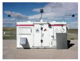
FIGURE 4-I Interim holding facility. SOURCE: Laurence G. Gottschalk, PMNSCM, “Non-Stockpile Chemical Materiel Project Program Status and Update,” presentation to the committee on September 27, 2011.
facility, the MARB holding facility. It remains there until the assessment is complete, whereupon it is placed in the third holding facility, called the interim holding facility. The munition is held there for up to 2 years, awaiting destruction in an EDS.
SINGLE CHEMICAL AGENT IDENTIFICATION SET ACCESS AND NEUTRALIZATION SYSTEM
The single CAIS access and neutralization system (SCANS) is a small polyolefin unit for detoxifying intact ampoules and bottles from CAIS. These approximately 4-oz bottles are placed in the unit with a 1-gal bottle of reagent, normally dichlorodimethylhydantoin in solution. After the unit is sealed, the bottles are ruptured with a mallet and plunger. The ingredients are mixed by manually shaking the unit (U.S. Army, 2011e). The system has been successfully used numerous times; the committee judges that it requires no further research.
SPECTROSCOPIC AND X-RAY ASSESSMENT
Digital Radiography and Computed Tomography
Digital radiography and computed tomography (DRCT) is a technology similar to a CAT scan. It uses X-rays to vertically scan a suspect CWM on a rotating platform. It produces a digital view of the munition interior, even through an overpack container. The DRCT requires an X-ray source and a detector. The detector records radiation that passes through the object being scanned. The intensity of the radiation arriving at the detector is attenuated by the objects in its path as a function of their density: The thicker, more dense the object, the greater the attenuation of the X-ray intensity. The object being scanned can be rotated or tilted to produce various views of the munition and its internals. A difference in level from tilt view to level view is useful in determining the presence of liquids in the suspected CWM. The DRCT can be operated from a remote location, allowing objects to be scanned from a safe distance (U.S. Army, 2011a).
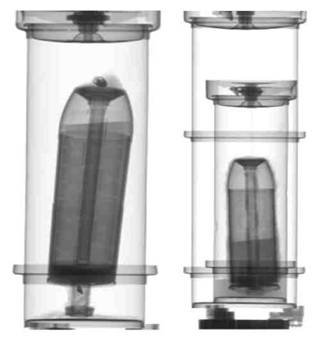
FIGURE 4-2 A typical DRCT scan. SOURCE: Franklin D. Hoffman, Chief, Operations Team, NSCMP, “Non-Stockpile Chemical Materiel Project Equipment and Capabilities Overview Equipment and Capabilities to NRC,” presentation to the committee on September 27, 2011.
A typical DRCT scan is seen in Figure 4-2. The container on the left shows that by tilting the container, the presence of liquid can be verified by a shift in the liquid level.
DRCT is a robust, proven technology. It is portable, can be operated remotely, can determine the presence of liquids, and can be used even if the suspected CWM is in an overpack. It cannot be used to determine the type of chemicals in a container.
The PMNSCM has mentioned that NSCMP is updating the DRCT with newer, commercial capabilities and integrating PINS and DRCT.16 However, the committee did not receive any detailed information on these development activities.
Although the portable isotopic neutron spectrometer (PINS) is considered the most effective tool for determining the presence of CWM inside a chemical munition or
![]()
16Laurence G. Gottschalk, PMNSCM, “Non-Stockpile Chemical Materiel Project Program Status and Update,” presentation to the committee on September 30, 2011.
container, DRCT has several capabilities that make it an important part of the MMAS.
Portable Isotopic Neutron Spectroscopy
PINS is regularly deployed in the field to identify the contents of sealed munitions suspected of containing chemical warfare materiel. Developed by Idaho National Laboratory, the PINS system has been patented and is commercially available through AMETEK, Inc., in Oak Ridge, Tennessee.17 This self-contained, nondestructive investigative tool is the first step in determining the proper neutralization procedure for found non-stockpile chemical weapons.
The PINS system contains a neutron source, californium-252. The neutrons pass through a polyethylene block and two tungsten plates, which serve to both slow the neutrons and absorb gamma radiation generated by the neutron source before passing through the munition mounted within the instrument (Caffrey et al., 1992). The neutrons pass through the steel walls of the munition and interact with the chemicals inside, generating a spectrum of gamma radiation via neutron capture, followed by prompt gamma-ray emission (Skoog et al., 1998). The gamma-ray emissions are detected using a multichannel analyzer that is able to filter the gamma radiation generated by the steel or aluminum casing. Data are displayed as a spectrum of counts versus the emitted gamma-ray energy, which is element- and isotope-specific (shown in units of kiloelectron volts, or keV). The emission energy peaks are analyzed by the software to generate an elemental ratio, or empirical formula, for the chemical materiel. The spectrum is then compared against a library of known spectra of chemical agents to identify the contents of the munition (Caffrey et al., 1992).
Significant advantages of the PINS system include portability and user-friendly automation. The setup for this system includes a daily background scan to account for local environmental factors, such as high hydrogen concentrations in wetland areas, high chlorine concentrations in coastal areas, and so on. In addition, the peak energies and relative intensities are unaffected by the possible degradation or polymerization of the chemical materiel, rendering the technology applicable to any intact chemical weapon. Lastly, PINS does not generate low-level radioactive material. The neutron capture method generates only very short-lived radionuclei (Caffrey et al., 1992).
While PINS is an essential tool in the assessment of recovered munitions, it is not totally reliable. See Chapter 7 for a discussion of this subject and for findings and recommendations related to PINS.
Raman spectrometry is used only to analyze liquids in recovered glass containers.18 These include the vials and ampoules from CAIS. Raman spectra are generated by the detection of scattered visible radiation. A sample is irradiated with monochromatic visible or near-infrared light, which is absorbed by the electrons. The electrons reemit the absorbed energy as infrared light, which is detected at an angle perpendicular to the light source. The spectrum that is generated yields structural information about the sample, as shown by the wavelength and intensity of the emitted infrared radiation.
MOBILE MUNITIONS ASSESSMENT SYSTEM
The MMAS is a transportable system equipped to analyze and provide on-site information about the contents of unidentified munitions without opening them (U.S. Army, 2011d). It was designed and built by the NSCMP to take instruments into the field, provide analysis, and communicate information to response personnel.
As shown in Figure 4-3, the MMAS is an operational platform that transports and contains the support needed to analyze the content of items. It contains nonintrusive assessment equipment such as instrumentation for PINS, DRCT, and Raman spectroscopy to assess conventional or chemical-filled munitions. It contains an onboard darkroom to process X-ray film and is equipped with sensors to constantly monitor weather conditions and cameras to monitor site activities. It includes a portable electric generator, which provides a constant power supply.
Data generated by the MMAS are stored in redundant computer systems equipped with battery backup. Satellite links, cellular phones, and shortwave radio ensure local emergency responders can be contacted in the case of an emergency. The MMAS contains equipment for decontamination of personal protective equipment (U.S. Army, 2005).
The MMASs are operated by CARA on behalf of NSCMP. There are three MMAS units located in the United States, two of which are at Aberdeen Proving Grounds in Maryland and one at Pine Bluff Arsenal in Arkansas.19
The DRCT and PINS data, pictures of munitions, and historical and other data are evaluated by the Materiel Assessment Review Board (MARB), which then recommends a method of disposing of the CWM. Chapter 2 describes the MARB’s activities.
![]()
17Available at http://www.inl.gov/research/portable-isotopic-neutron-spectroscopy-system/. Accessed on March 15, 2012.
18Laurence G. Gottschalk, PMNSCM, “Non-Stockpile Chemical Materiel Project Program Status and Update,” presentation to the committee on September 30, 2011.
19Franklin D. Hoffman, Chief, Operations Team, NSCMP, “Non-Stockpile Chemical Materiel Project Equipment and Capabilities Overview,” presentation to the committee on September 27, 2011.
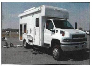
FIGURE 4-3 Mobile munitions assessment system. Contents include heating and air conditioning system; electrical power supply and distribution system; PINS system; radiography systems; Raman spectroscopy system; data acquisition and handling system; audio/video equipment; communications equipment; and support equipment. SOURCE: Laurence G. Gottschalk, PMNSCM, “Program Status and Update to NRC,” presentation to the committee on September 27, 2011.
In this section, four systems, each employing one of three technologies that have been used to destroy chemical munitions are described. Each has been used abroad and/or in the United States. One system, the EDS, uses explosive charges only to access the agent cavity in the munition body and uses a liquid reagent to neutralize the agent. Secondary wastes include a liquid neutralent, rinsates, and metal fragments. Another system, the SDC, does not use external explosives at all but depends on electric heating or heat from previous detonations to detonate or deflagrate the munition and destroy the agent in a sealed chamber. Primary effluents are metal fragments, treated off-gases, and dry spent scrubber solution salts from the spray dryer.
The remaining two systems, the TDC and the DAVINCH, are similar in that they both use external charges to access the agent cavity in a sealed chamber (as does the EDS), but unlike the EDS, they also use the detonation to destroy the agent. These technology variants differ in terms of detonation conditions, off-gas treatment, explosion containment capacity, and other operating parameters. Their primary effluents are metal munition fragments, treated off-gases, and, in the case of the TDC, also gravel dust and spent lime.
An overview of the four systems, showing several key differences and similarities between them, is provided in Table 4-2. In the text that follows, the systems are described in greater detail and their experience to date in destroying chemical munitions is summarized.
At sites where some RCWM consists of munition bodies, containers, and scrap metal that contain only traces of agent and where there is no need for placing donor and shaped charges to access the agent cavity in munition bodies, the use of the EDS, TDC, or DAVINCH may not be warranted. At such sites, it is probably more practical to use an alternative method—for example, metal parts treatment, heating in an SDC, or chemical neutralization—to destroy remaining agent residue and heels. For sites at which some of the RCWM consists of munitions and containers that are still filled with agent, one or more of the technologies summarized above may be used, depending on site-specific needs and technology capabilities.
The EDS is a system designed by NSCMP. Sandia National Laboratories has built five to date, for on-site destruction of recovered chemical weapons or treatment of other chemical warfare materiel. Two versions, the EDS Phase 1 (EDS-1) and the EDS Phase 2 (EDS-2) (see Figure 4-4), have been built and operated, with the EDS-2 being a later design and, in general, able to destroy more and larger munitions than the EDS-1. Information on the two systems is available from several sources, including NRC, 2006, 2009a, and 2010b.
Both EDS-1 and EDS-2 employ shaped cutting charges to explosively open one or more containers or munitions placed within a closed, sealed containment vessel, thereby releasing the agent contained within the container(s) or munition(s). Any energetics contained within a munition before treatment will be destroyed by the explosive shaped charge. Chemical
TABLE 4-2 Comparison of Destruction Technologies
|
|
||||
|---|---|---|---|---|
| Technology Type | ||||
| Neutralization | Explosive Destruction | Explosive Destruction | Thermal Destruction | |
| Technology Attribute | EDS Sandia, NSCMP | TDC CH2M HILL | DAVINCH Kobe Steel | SDC Dynasafe |
|
|
||||
| Agent contained in: | Sealed cylindrical vessel on truck bed | Rectangular detonation chamber | Double walled cylindrical detonation vessel | Spheroid double walled static kiln |
| Agent in munition accessed by: | Shaped charges on munition or munition overpack | Donor charge placed around munition or munition overpack | Shaped and donor charges on munition or munition overpack | Heating of munition, followed by deflagration or detonation |
| Agent destroyed by: | Reaction with reagenta in vessel at 60° for 1 hr followed by 2-hr hot water rinse | Detonation: Heat and pressure from controlled detonation at 700°-1000° | Detonation: Shock wave, compression, thermal destruction in fireball at 2000°C | Heating to 550° resulting in agent decomposition |
| Typical cycle time (varies with munition) | 48 hr | 35-40 minutes | 100 minutesb | 20-30 minutes |
| Off-gas treatment | None. Agent and reagent react until agent is destroyed. No off-gas produced. | Catalytic oxidizer with max temperature of 1095°C; reactive bed filter with hydrated lime or sodium bicarbonate for acid neutralization; carbon adsorption system; ceramic filter and HEPA for particulates | Cold plasma oxidizer (Glid-Arc) at 600°C, 0.5-1.0 sec residence time; in-line gas scrubber with NaOH washdown to neutralize the gas; sulfur-impregnated carbon and activated carbon; HEPA filters for particulates | Thermal oxidizer at 1100°C, 2 sec residence time; acid scrubber at approx. 80°C; IONEX filter containing HEPAfilter, sulfur-impregnated carbon, and activated carbon; baghouse filter and HEPA for particulatesc |
| Waste streams | Liquid neutralent and rinsate, scrap metal (munition fragments). Discharged scrap metal is .1 VSLd (formerly 3X) | Exhaust gas, metal fragments, gravel dust, spent lime, activated carbon. Discharged scrap metal is .1 VSL (formerly 3X) | Metal fragments, exhaust gas, dust, activated carbon, scrubber condensate water. Discharged scrap metal is .1 VSL (formerly 3X) | Metal fragments, scrubbed off-gas, dust, salts, activated carbon. Scrap metal suitable for release for unrestricted use (formerly 5X) |
| Ability to recycle or further treat off-gas | N.A. No gas stream is produced. | None. Has expansion tank for off-gas but no ability to recycle | Yes. Can recycle off-gas through cold plasma oxidizer after holding and testing in off-gas retention tank | Yes. If operated in batch mode, off-gas in the static kiln can be held at 550° and tested until agent is not detected |
| Transportability | Transportable on one trailer | Transportable on 8 trailers, 10 days | Fixed facility but vessel can be moved on three flatbed trailers (one each for the outer chamber, the inner chamber, and the lid) plus two trailers for the off-gas treatment unit and additional trailers as needed for supporting equipment | Fixed facility but can be moved in 20-25 ISO containers |
| Explosive containment capacity, TNT-equivalent | 5 lb for EDS-2, including shaped charges | 40 lb including donor charge | 99-143 kg, including donor and shaped charges | 5 lb in munition |
| Largest munition | 155-mm projectile | 210-mm projectile | 8-in. projectile, overpacked M55 rocket | 8-in. projectile |
|
|
||||
NOTE: ISO, International Standards Organization; HEPA, high-efficiency particulate air filter; NaOH, sodium hydroxide; IONEX, a research company; 3X, level of agent decontamination suitable for transport for further processing (obsolete); 5X, level of agent decontamination suitable for commercial release (obsolete); TNT, trinitrotoluene.
aReagent is monoethanolamine for mustard and NaOH for phosgene and other fills.
bBased on experience to date of six cycles per 10-hr day.
cIn this report, IONEX refers to an off-gas treatment system that contains particulate filters and activated carbon adsorbers (NRC, 2010b).
dVSL is a control limit used to clear materials for off-site shipment based on agent concentration in the atmosphere above the packaged waste materials. The numerical value of the VSL can depend on the permit issued by the regulatory authority for the particular facility involved, but it is often set at either the STEL or the short-term limit (STL), which is numerically the STEL but without the 15-min time component. See Chapter 3 of reference NRC, 2007 for an in-depth discussion of the issues surrounding off site shipment of partially decontaminated waste.
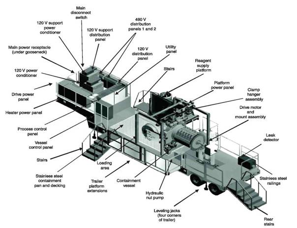
FIGURE 4-4 The EDS-2 vessel on its trailer. SOURCE: NRC, 2009a.
reagents are then added to the vessel to neutralize the agent released from the munition. The EDS-1 containment vessel has a 1-lb TNT-equivalent net explosive weight (NEW) limit, with the NEW limit including both the explosives contained in the munition and those in the cutting charges; the EDS-2 containment vessel has a 4.8-lb TNT-equivalent NEW limit.
The EDS-1 has been used in a number of field operations, including those at Rocky Mountain Arsenal, Colorado [10 sarin (GB) bomblets]; Camp Sibert, Alabama [11 munitions]; and Spring Valley in Washington, D.C. [16 mustard agent (HD) 75-mm artillery projectiles, 1 lewisite 75-mm projectile, and 3 arsine-containing 75-mm projectiles]. One EDS-1 and two EDS-2s were then employed at the Pine Bluff Arsenal to destroy 1,227 recovered chemical munitions. Many of the munitions at Pine Bluff were degraded from burial and not considered safe for dismantling.
Several steps in the EDS operational procedures involve waiting for analytical results or for heating and cooling, resulting in a cycle time of 2 days.
Relative to other transportable whole-munition destruction systems, such as the Dynasafe static detonation chamber, the CH2M HILL transportable detonation chamber, and the DAVINCH system, the EDS-1 and -2 have long cycle times.
In the EDS, the munition is opened with a shaped explosive charge. For HD, most of the agent is destroyed by react-rted to outline.) ing it with a 90 percent MEA/10 percent water solution at 60°C while rotating the vessel for 1 hr. In a subsequent step, water at 60°C is added to the vessel, the vessel contents are heated to 100°C, and the vessel is rotated for 2 hr. This step is needed to disperse or dissolve the solid or semisolid heels that occur in many mustard-filled munitions and to remove the mustard from the chunks or globules of heel and other solid residues. The water-mustard chemical reaction is very fast, with a half-life of about 2.3 sec at 90°C (NRC, 1993), but the diffusion operations involved in this step are much slower, often resulting in a much slower rate of destruction of mustard than implied by the mustard-water chemical reaction. Further, use of still higher temperatures or changing other operational parameters will not appreciably increase the rate of these diffusion operations.
The entire mustard destruction step takes 9 to 10 hr. The equivalent steps in the TDC and DAVINCH are practically instantaneous. Changes can be made to speed up some of the steps in the EDS process—for example, steam injection to reduce vessel heating time—but it will always be slow relative to the TDC and DAVINCH.
To address the slow processing rate and other issues, the NSCMP has begun product improvements to the EDS:
• Impulsively loaded vessels.20 The chambers of all existing EDS chambers are certified as pressure vessels. The American Society of Mechanical Engineers has established a new category, impulsively loaded vessel, with a code stamp U3. Future EDS-2 vessels will have the U3 stamp and will have a 9-lb NEW rating. The Department of Defense Explosives Safety Board (DDESB) will require testing with explosive charges to certify this rating.
• EDS-2 test fixture. This is a functional but nonmobile EDS-2 that will allow for more rapid testing of product improvements. It utilizes an existing EDS-2 vessel. Construction was completed in the fourth quarter of 2011. Testing with agent was planned for the first quarter of 2012.
• Three-piece clamp. This is a previously designed but never implemented end closure for the EDS. It offers automated bolt tightening. Its advantages over the current design include less operator stress, better alignment between the end closure and the vessel, and a significant saving of time. A clamp of this design is to be installed on the new EDS-2 test fixture.
• Liquid analyzer. A near-real-time analyzer that determines whether or not the neutralizing reactions are sufficiently complete to allow EDS vessel draining is being developed. A 10-sec cycle is anticipated. Semi-quantitative testing was reported to be successful for mustard and lewisite agents. Plans called for using the analyzer during the testing of steam injection in the first quarter of fiscal year 2012. These tests were also to include the addition of cold water to more rapidly cool the vessel after the 2-hr water rinse at 100°C. This will decrease the duration of the 1-hr liquid analysis time, which now starts at 1145 and ends at 1245 on Day 1.
• Use of a laser for surface decontamination. A commercially available laser from ADAPT Laser is being evaluated for removal of heavy metals from the EDS vessel interior and for similar applications elsewhere. Testing on moderately contaminated surfaces was successful. As of September 2011, testing on more heavily contaminated surfaces was planned.
• Processing munitions in overpacks. Use of improved linear shaped charges to cut through the overpack and the munition was planned as of September 2011. This could allow the processing of leaking munitions more safely.
• Steam injection. Injection of steam into the EDS vessel is to be tested. Expected advantages of using steam injection include faster heating than is now obtained, by heating with external band heaters only, and reduced liquid waste. Steam injection is being installed and tested on the EDS-2 test fixture mentioned above. Testing with live agent was planned for 2012.
• The EDS-3. Simulation studies and modeling are under way on a potential new EDS design, termed the EDS-3. It would be similar to the EDS-2 but would be able to accommodate a complete M55 115-mm rocket contained within an overpack.
In addition to these product improvements, efforts are under way on the identification of a reagent that will be effective for all agents. Testing of 10 reagents on mustard and GD (soman) agents has begun, with results pending.
Transportable Detonation Chamber
The TDC was first described in the NRC report on international technologies for destruction of RCWM (NRC, 2006). A subsequent report outlined the updates, with an emphasis on the Blue Grass and Pueblo chemical agent destruction pilot plants (NRC, 2009a). The TDC was designed by CH2M HILL Demilitarization, Inc.
The TDC is a true explosive destruction system, as it uses the heat and pressure generated by an explosion to destroy most of the chemical agent fill. The current system was extensively tested and modified between 2003 and 2006 at Porton Down, England. This system evolved into the TC-60, with a DDESB NEW rating of 40 lb TNT-equivalent. The TC-60 unit was used in 2008 to destroy several dozen munitions at the Schofield Barracks in Hawaii. It was then returned to the Aberdeen Proving Ground for substantial additional testing and development work. It was most recently employed in Columboola, Queensland, Australia. The current configuration of the TC-60 system is shown in Figure 4-5. The system has demonstrated the ability to destroy mustard, phosgene, chloropicrin, white phosphorus, smoke, and the vomiting agent Clark.21
As shown in the figure, the detonation chamber is followed by an extensive pollution control system, including a catalytic oxidizer, a heat exchanger, carbon filters, and a HEPA filter. The gas is discharged into the system enclosure, which has an additional carbon filtration system, before exhausting into the atmosphere. The munitions are wrapped in an explosive charge and oxygen is injected prior to detonation.
![]()
20Impulsive loading is defined as a “loading whose duration is a fraction of the periods of the significant dynamic response modes of the vessel components. For the vessel, this fraction is limited to less than 35 percent of the fundamental, membrane-stress dominated (breathing) mode.” From ASME Case 2564-1. Available at http://cstools.asme.org/csconnect/pdf/R081171.pdf.
21Brint Bixler, Vice President, CH2M HILL, “Controlled Detonation Chamber,” presentation to the committee on December 13, 2011.
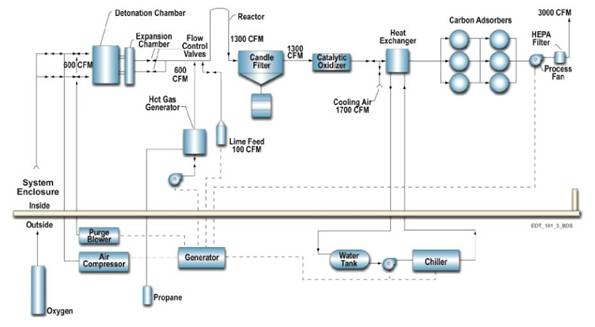
FIGURE 4-5 Process flow in the large mobile transportable detonation chamber TC-60. SOURCE: Brint Bixler, Vice President, CH2M HILL, “Controlled Detonation Chamber,” presentation to the committee on December 13, 2011.
There have been a number of lessons learned and upgrades to the system, including the following:22
• Additional chamber floor protection was added.
• The efficiency of the final filtration was improved with the addition of a HEPA filter.
• Internal welds for the fasteners attaching the armor plate to the chamber walls were upgraded.
• The firing system was improved by changing the firing plug/cable design and replacing the system every 70 detonations.
At Aberdeen Proving Ground, 29 cylinders of HD were destroyed, for a total of 282 lb HD between March 2009 and March 2010. Included were two cylinders in double overpacks, with 11.7-lb of HD (155-mm projectile equivalent). Overpack test results showed that the outer and inner overpacks had been penetrated and that there was sufficient heat to destroy the chemical fill.
An additional upgrade was made just prior to transport to Columboola. Improved bearings were added to two control valves, one 3-in. and the other 10-in. The unit had been in storage for a while and moisture buildup was causing the valves to seize. The unit was set up in Columboola and ready within 10 days. The typical schedule included 2 days of destruction followed by one-half day of “scrap management.” Operations then continued. Destruction rates stabilized at eight munitions per day. Scrap was removed from the detonation chamber twice per week. The campaign ended with treatment of 144 mustard-filled munitions, many with heels.23 ECBC staff who observed its use in Columboola praised it as “elegant” to operate.24 There were no problems with the unit other than the cracked welds. The operator believed the unit was a good transportable system with a throughput midway between that of the EDS (slower) and that of the Dynasafe SDC (faster).
Dynasafe Static Detonation Chamber
The SDC was described in three earlier reports (NRC, 2006, 2009a, and 2010b). It is the only one of the four systems that does not require any preparation of the CWM prior to destruction, which gives it an important safety advantage over the other systems. Moreover, the scrap metal produced is suitable for release for unrestricted use (formerly termed “5X”), and no donor explosives are required.
The design and operation of the SDC 2000 system in Munster, Germany, were described in detail in previous NRC reports (NRC, 2006 and 2009a). An SDC 1200 was delivered to the JFE Steel Corporation in Japan in 2009.25 It will be used for the destruction of RCWM in Chiba Prefecture, Japan. Another SDC 1200 was delivered to Kawasaki Heavy
![]()
22Ibid.
23Ibid.
24Timothy A. Blades, Deputy Director, Directorate of Program Integration, ECBC, teleconference with Richard Ayen, committee chair; Doug Medville and JoAnn Lighty, committee members; and Nancy Schulte, NRC study director, January 4, 2012.
25Harley Heaton, Vice President-Research, UXB International, “Dynasafe Static Detonation Chamber,” presentation to the committee on December 13, 2011.
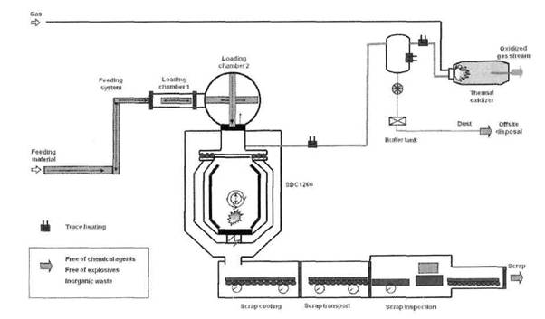
FIGURE 4-6 Process flow diagram for front components of the Dynasafe SDC 1200 installation for Anniston Army Depot. SOURCE: Adapted from personal communication between Holger Weigel, Vice President, Dynasafe International, and Managing Director, Dynasafe Germany, and Richard Ayen, committee chair, May 12, 2010.
Industries and is now undergoing systemization. It will be used for the destruction of Second World War–era Japanese RCWM in Haerba-ling, China.
The NRC letter report “Review of the Design of the Dynasafe Static Detonation Chamber (SDC) System for the Anniston Chemical Agent Disposal Facility-August 25, 2010” describes the Dynasafe SDC 1200 system now installed at the Anniston Chemical Agent Disposal Facility (ANCDF), in Alabama (see Figure 4-6).
The Dynasafe 1200 used at ANCDF had a NEW containment capacity of 5 lb, all of which consists of explosives in the munition since no donor charge is needed. As of September 1, 2011, this system had destroyed 2,322 munitions, consisting of normally configured and overpacked 4.2-in., 105-mm, and 155-mm mustard-filled rounds.26
During operations at ANCDF, a number of problems with the system became evident, the most significant being agent migration into secondary containment.27 Agent was leaking at a number of locations. The actions taken to alleviate the leaking were these:
• Agent leaks from the buffer tank into the solids collection drum below the buffer tank were eliminated by blind-flanging the connection to the solids collection drum from the buffer tank.
• The leaking of agent from loading chamber 2 into the process air system was alleviated by modifying the loading chamber 1/loading chamber 2 pressure equalization procedure during munitions feed to the detonation chamber.
• Agent was detected at the process air monitors during emptying of the detonation chamber. This was alleviated by controlled venting of loading chamber 2 and the detonation chamber before beginning to empty the chamber.
• Agent was escaping from one or more of the flange connections between the detonation chamber and the thermal oxidizer. This was being investigated as this report was being written, with emphasis on different gasket materials or use of sealants.
The unsteady nature of events in the detonation chamber during operations in 2011 appeared to be causing CO excursions in the off-gases from the thermal oxidizer. The short residence time in the thermal oxidizer might also have been contributing to the problem (NRC, 2010b). The instability in the detonation chamber was apparently causing unsteady flow through the thermal oxidizer: The problem was allevi-
![]()
26Timothy K. Garrett, Site Project Manager, ANCDF, “Dynasafe Static Detonation Chamber,” presentation to the committee on September 29, 2011.
27Charles Wood, ANCDF Deputy Operations Manager, URS, ANCDF, presentation to the committee on September 29, 2011.
ated by installing a smaller orifice between the detonation chamber and the thermal oxidizer to smooth flow to the oxidizer. Also, the flow rates of the spray dryer atomizing air and the barrier air were reduced, allowing more air at the thermal oxidizer. (See the fourth bullet item in the list of issues being addressed for further discussion of this topic.)
Rapid depletion of carbon was attributed to the presence of sulfur dioxide in the offgases fed to the carbon beds. The excessive sulfur dioxide emissions problem, and hence the rapid carbon depletion problem, was resolved by adjusting the pH in the scrubbers.
As of January 2012, effort was continuing at the ANCDF to eliminate or further alleviate the problems described above, as well as to satisfy other identified development needs.28 Conventional munitions were of necessity being employed in this critical development effort since Anniston no longer had any chemical munitions. This work was being carried out jointly with Dynasafe, and the lessons learned and the resulting design changes were being incorporated into future SDC 1200 systems. As of January 2012, the following issues were being addressed:
• Process gases were leaking through the knife valves at the bottom of the buffer tank. New valves of an improved design had been received and were to be installed before start-up of an assessment of throughput, reliability, availability, and maintainability (TRAM) for the system.
• Agent vapor from the upper portion of the detonation chamber was escaping to the process air system as the chamber was emptied. In addition to implementing a controlled venting procedure, as previously described, a new nozzle was being installed to keep the top of the chamber hotter, minimizing agent vapor generation at the interface between loading chamber 2 and the detonation chamber.
• Agent was escaping from one or more of the flange connections between the detonation chamber and the thermal oxidizer. It was planned to inspect, measure, and adjust all connections to ensure proper alignment and gasket seating before the start of the TRAM assessment.
• CO excursions in the offgases from the thermal oxidizer were being experienced. The problem was greatly reduced by the actions already described. In addition, design studies were begun aimed at providing additional gas flow through the system by upgrading the induced draft fan and the fan in the filter system between the induced draft fan and the stack (the IONEX Research Corporation system). Since the ANCDF SDC was manufactured, Dynasafe has enlarged the thermal oxidizer for its SDC 1200s.29 This is expected to allow better control of excess oxygen and hence more reliable combustion of CO.
• Occasional failure of loading gate 2 seals was being investigated.
• Degradation of the spray dryer temperature control valve was addressed by installing a redundant system to be tested during the TRAM assessment.
• A process water piping degradation problem was addressed by upgrading materials to stainless steel. The new piping was to be installed before the TRAM assessment.
• Bridging of solids in the baghouse was being addressed by designing and installing an automated vibrator.
• Accumulation of solids in the spray dryer was alleviated by system tuning and better pH control. The situation was to be monitored and further evaluated during the TRAM assessment.
• The bypass between loading chamber 2 and the detonation chamber occasionally became clogged. This situation was still being evaluated as of January 2012.
This unit completed its intended operation on chemical munitions at ANCDF and is available for use by NSCMP for the destruction of RCWM.
Detonation of Ammunition in a Vacuum Integrated Chamber
DAVINCH is a controlled detonation system for the disposal of chemical munitions. It is yet another destruction system where an explosion consumes most of the agent.
The DAVINCH technology was developed by Kobelco, a subsidiary of the Japanese company Kobe Steel, a manufacturer of large steel pressure vessels. DAVINCH was developed to destroy Japanese chemical bombs, some containing a mustard/Lewisite mixture and others containing vomiting agents. Munitions placed in the DAVINCH vessel are detonated in a near vacuum using linear shaped charges and a donor charge that is placed on the munitions overpack to open the munitions and access the chemical agent (see Figure 4-7).
The agent is destroyed by the high temperatures (3000°K) and pressures (10 GPa) that result from the detonation and from the fireball in the chamber. The use of a vacuum reduces noise, vibration, and blast pressure, thus increasing vessel life. The off-gases that are produced are treated in a cold plasma oxidizer followed by treatment in activated carbon filters. The explosion containment capability of DAVINCH chambers varies from 99-143 lbs TNT-equivalent NEW, depending on the application. Detailed descriptions of the
![]()
28Timothy Garrett, Site Project Manager, Anniston Chemical Agent Disposal Facility, personal communication to Nancy Schulte, study director, National Research Council, January 26, 2012.
29Harley Heaton, Vice President-Research, UXB International, personal correspondence to Nancy Schulte, NRC study director, March 16, 2012.
DAVINCH technology were provided in previous NRC reports (NRC, 2006 and 2009a).
United States
To date, the DAVINCH technology has not been used in the United States. A DV60 (60-kg TNT-equivalent explosion containment capacity) had been leased from Kobelco by the U.S. Army for use at the Tooele Chemical Agent Disposal Facility (TOCDF), in Utah. However, an alternative method of destroying the munitions became available before the DAVINCH was due to start up in early 2012. Because this alternative was successful, it was decided in late 2011 not to use the DAVINCH at TOCDF.
Japan
The DAVINCH technology was used at Kanda Port in Japan to destroy recovered Second World War–era bombs containing chemical warfare materiel. Some of the bombs contained a mixture of mustard agent and lewisite; others contained Clark I and Clark II vomiting agents (DC/DA). As of 2009, 2,050 of these bombs had been destroyed (NRC, 2009a).
Belgium
The Belgian Ministry of Defense has installed a DAVINCH system having a 50-kg TNT-equivalent explosion containment capacity at a Belgian military facility at Poelkapelle. By December 2011, over 4,000 munitions containing chemical agent had been destroyed.
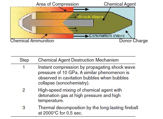
FIGURE 4-7 DAVINCH three-stage destruction mechanism. SOURCE: NRC, 2006.
People’s Republic of China
DAVINCH units are being used in the People’s Republic of China (PRC) to destroy Second World War–era Japanese chemical munitions filled with blister, choking, vomiting, and other agents. These munitions are primarily artillery shells and bombs ranging in size from 75 mm to 150 mm. The site with the most RCWM, Haerba-ling (northeastern China), contains an estimated 300,000-400,000 munitions; another 47,000 munitions have been recovered at 26 other locations. At Haerba-ling, both a DAVINCH and a Dynasafe SDC will be used to destroy munitions recovered from pits where they are buried. The second largest site in the PRC is in Nanjing, where 36,000 chemical munitions have been recovered. At this location, two DAVINCH DV-50 units, operating in tandem, are in use. Between September 1, 2010, and June 10, 2011, 25,000 overpacked and boxed munitions were destroyed.
In addition to these transportable (but barely so) units, Kobelco states that a lighter, more mobile version of DAVINCH, called DAVINCHlite, is being developed. The committee believes that, as of early 2012, the DAVINCHlite had not even been manufactured much less used to destroy any RCWM in the PRC.
SECONDARY WASTE STORAGE AND DISPOSAL
As indicated previously, the treatment technology for RCWM will involve either the EDS, one of the EDTs, or perhaps a combination of these technologies. Each of these technologies will produce a number of secondary waste streams (see Table 4-2) that will then need to be managed
in accordance with regulatory requirements. The regulatory requirements pertain primarily to the Resource Conservation and Recovery Act (RCRA) and its implementing regulations. RCRA is summarized in Appendix D, along with other regulatory programs.
The secondary wastes produced by the various types of EDTs are similar; they consist of metal casings and fragments, explosive fragmentation protective materials, carbon filter material, baghouse dusts, miscellaneous wastes (used O-rings, fittings, etc.), and liquid waste streams coming from off-gas treatment, from periodic cleaning and decontamination of the device, or from closure between deployments. The EDS will generate not only the above materials but also a substantial volume of liquid wastes (hydrolysates and various dilute rinsates). CAIS containing dilute or neat agent are treated and disposed of in a SCANS unit, as discussed above.
Secondary waste from EDS operations was stored at both the Spring Valley and Camp Sibert sites and then shipped off-site.30,31 At both sites, the project managers followed the Army’s general practice of treating the waste only to the point at which it can be safely shipped off-site to commercial treatment, storage, and disposal facilities (TSDFs) (NRC, 2004). At both places, the waste was stored in a less-than-90-day hazardous waste storage area. The waste was placed in an enclosed trailer (Spring Valley) or in a vapor containment structure (Camp Sibert). The enclosures were within fences, with security guards present. Liquid waste was placed in 55-gal steel drums.
For the past several years, NSCMP has maintained a waste management contract with Shaw Environmental, Inc. As explained in NRC, 2004, the waste management contractor is responsible for teaming with one or more commercial hazardous waste TSDFs to transport and dispose of hazardous secondary and neutralent wastes from the various NSCMP projects. Shaw Environmental fulfilled this responsibility for EDS operations at both Spring Valley and Camp Sibert. The project manager at Spring Valley reported that he received some questions and expressions of concern from the regulators and the community about the nature and amounts of reagents and waste entering and leaving the facility, but that this was “nothing really significant.”
Otherwise, there were no problems with waste storage or disposal at either Spring Valley or Camp Sibert. As a consequence, the committee could not identify any need for targeted research and development in this area.
![]()
30Karl E. Blankinship, FUDS Project Manager, Mobile District U.S. Army Corps of Engineers, personal communication to Nancy Schulte, NRC study director, April 4, 2012.
31Dan G. Noble, Project Manager, Spring Valley, Baltimore District, U.S. Army Corps of Engineers, personal communication to Nancy Schulte, NRC study director, March 30, 2012.


