
MISSILE DEFENSE AGENCY
The Missile Defense Agency (MDA) employs a capabilities analysis process for establishing requirements that relies heavily on modeling and simulation.1 The MDA seeks to engage the services and Combatant Commands (COCOMs) in the process. Exempt from the Joint Capabilities Integration and Development System (JCIDS) requirements process, MDA has implemented the Warfighter Involvement Process (WIP), represented in Figure C-1.
The WIP is designed to align the MDA program with warfighter priorities for missile defense in a streamlined manner. The process starts with the U.S. Strategic Command (USSTRATCOM) soliciting COCOM inputs, which are based on the Defense Planning Guidance, threat developments, and the commander’s intent. The MDA consolidates and prioritizes these inputs into a Prioritized Capability List (PCL). The PCL is intended to be written as capability needs, not to include specifics of weapon system solutions. Within the JCIDS process, it is analogous to the Initial Capability Document (ICD).
The MDA receives the PCL and performs an analysis of the baseline Program of Record (PoR) in order to identify gaps in capability. The MDA captures the parameters associated with the Ballistic Missile Defense System (BMDS) elements,
_______
1Further information on MDA’s testing and capabilities analysis process is available through the MDA web site: “Supporting Efforts: Ballistic Missile Defense Testing.” Available at http://www.mda.mil/system/testing.html. Accessed February 28, 2012.
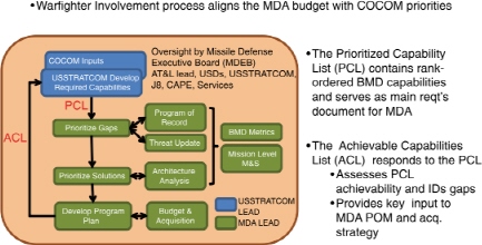
FIGURE C-1 The Missile Defense Agency’s (MDA’s) Warfighter Involvement Process. NOTE: Acronyms are defined in the list in the front matter. SOURCE: Missile Defense Agency.
as funded in the PoR, in the Element/Component Characterizations for Analysis (E/CCA). The threat picture is also updated with the latest intelligence assessments. The E/CCA and the updated threat picture are the analytic basis for identifying gaps relative to the PCL. Element-level models such as the Aerospace Corporation’s System Performance Evaluation Tool (SPET) model for space-system tracking quality are used to generate element capability parameters that are used in BMDS engagement-level modeling (e.g., WILMA). These top-level models are used to generate the BMDS-level metrics, including defended area, raid capacity, probability of engagement success, among others. The MDA architecture team performs architecture assessment and proposes solutions to mitigate the gaps. These potential solutions are assessed for gap closure using the same modeling and analysis tools.
Proposed solutions are prioritized by senior MDA leadership, and the highest-priority solutions are selected for further requirements assessment, design work, and top-level costing. The element-level requirements process is unlike the JCIDS process in that the systems engineering and architecture process flows requirements down from the PCL rather than performance requirements being directly provided by the users. The lead services still provide Doctrine, Organization, Training, Materiel, Leadership and Education, Personnel and Facilities (DOTMLPF) requirements directly. The prioritized solutions are evaluated against the anticipated budgets, and the director-approved Achievable Capabilities List (ACL) is briefed to the Missile Defense Executive Board for final approval. The ACL is then provided to USSTRATCOM as a response to the PCL. The element program modifications and new program starts are approved by Office of the Under Secretary of Defense for
Acquisition, Technology, and Logistics (OUSD[AT&L]). The MDA uses a number of tools that have been developed over time, including the following:
• The WILMA-Suite is an end-to-end modeling and analysis suite for BMDS concept exploration used to predict the performance of missile defense architectures. WILMA is a medium-fidelity end-to-end simulation evaluation of missile defense architecture effectiveness, with consideration for battle planning, communications, and integration alternatives. WILMA may also be run in a higher-fidelity mode, used in conjunction with other in-depth element, engineering, environment, phenomenology, and threat models to make detailed assessments of missile defense system performance against adversary ballistic missile attacks.
• The SPET models space-sensor architecture performance, including multi-target tracking, scheduling, and handling association errors. SPET provides ground-, air-, and space-infrared (IR)/visible-sensor system performance against missile threat scenarios; the tool provides target signatures, coverage analysis, position and velocity tracking accuracy distributions, and interceptor effectiveness.
• SYSSIM (System Simulation) also models space-sensor architecture performance and includes interceptor flyouts (surface- or air-based). SYSSIM models the interceptor’s kinematic flyout or reach and also the probability of kill (Pk) of the engagement. SYSSIM provides engagement time lines and Pk as a function of space-/air-/ground-sensor tracking accuracy.
Observations and Attributes
Although the MDA process described above is specific to MDA requirements, it necessarily considers intelligence, surveillance, and reconnaissance (ISR) architectural assets (particularly communications and PCPAD/TCPED [planning and direction, collection, processing and exploitation, analysis and production, and dissemination/tasking, collecting, processing, exploiting, and disseminating]) in order to deliver required capability. The MDA is exempt from the JCIDS process, which streamlines decision time lines somewhat and has fostered the development of a set of analysis tools that continue to evolve.
OPERATIONALLY RESPONSIVE SPACE OFFICE
The Operationally Responsive Space (ORS) Office was established (1) to contribute to the development of low-cost, rapid-reaction payloads, buses, spacelift, and launch-control capabilities in order to fulfill Joint military operational requirements for on-demand support and reconstitution; and (2) to coordinate and
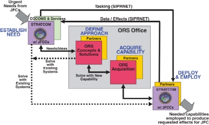
FIGURE C-2 The Operationally Responsive Space (ORS) Office process provides three tiers of response. SOURCE: ORS Office.
execute operationally responsive space efforts across the Department of Defense (DoD) with respect to planning, acquisition, and operations.2 The ORS Office receives its tasking and requirements from the Commander, U.S. Strategic Command (CDRUSSTRATCOM) and has a streamlined reporting structure directly to the DoD Executive Agent (EA) for Space.3 CDRUSSTRATCOM developed an initial concept of operations (CONOPS) for the ORS Office that specifies a number of warfighting effects expected by achieving an ORS end-state. Those effects are the abilities to reconstitute lost capabilities, to augment or surge existing capabilities, to fill unanticipated gaps in capabilities, to exploit new technical and operational innovations, to respond to unforeseen or episodic events, and to enhance survivability and deterrence. Additionally, the CONOPS provides a requirement to develop a three-tiered approach for delivering capability, as shown in Figure C-2.4
The Tier 1 requirement is the ability to employ existing space assets (on orbit) in minutes to hours in order to meet an unforeseen need. The Tier 2 requirement
_______
2Information on the mission of the ORS Office is available at http://ors.csd.disa.mil/mission/index.html. Accessed February 28, 2012.
3Col Ken McLaughlin, Director, ORS Office. 2007. “Operationally Responsive Space Office.” Slides dated July 2007. Available at http://www.responsivespace.com/ors/reference/McLaughlin.pdf. Accessed February 28, 2012.
4ORS Program Office. More information on the three tiers of response is available at http://ors.csd.disa.mil/tier-1/index.html. Accessed February 28, 2012.
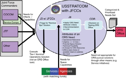
FIGURE C-3 Step 1 of the Operationally Responsive Space (ORS) Office process: Establish need. SOURCE: ORS Office.
is the ability to launch and/or deploy “field ready” assets in days to weeks; this implies an “on call” capability. The Tier 3 requirement is the ability to rapidly develop and transition to delivery a new or modified capability in months (not years). CDRUSSTRATCOM has developed a process of seeking urgent needs from combatant commanders and then prioritizing these needs and assigning tasking to the ORS Office, which develops alternatives to meeting the urgent need. This process is depicted in Figure C-3.
After establishing the need, the ORS Office then defines the approach to meeting the identified need, which involves collaboration and iteration, as shown in Figure C-4. Here, requirements are defined, prioritized, and validated; then a solutions analysis process follows, which is ultimately presented to CDRUSSTRATCOM and the EA for Space.
In addition to using subject-matter experts, the ORS Office uses several tools that fall into five categories, described briefly below. Of note, the tools help implement the process more effectively and serve as aids to inform decisions.
Architecting Tools
The ORS Office response to urgent needs is really an analysis of alternatives in a very compressed time line (typically 45 days from receipt of task from CDRUSSTRATCOM to the delivery of recommended courses of action to both
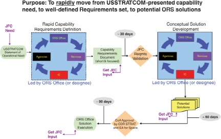
FIGURE C-4 Step 2 of the U.S. Strategic Command (USSTRATCOM) process: Define approach. SOURCE: ORS Office.
CDRUSSTRATCOM and DoD EA for Space). ORS personnel typically use a variation of the Aerospace Systems Architecting Process (ASAP). The key is getting the purpose analysis and problem framing done right up-front, by converting the Statement of Need from the requesting Joint Force Commander or Joint Functional Component Commander into the Capabilities Requirements Document (CRD). The CRD contains a list of prioritized evaluation criteria from the user that help evaluate courses of actions.
Interacting/Communicating Tools
When the requirements and concepts/solutions teams are working and having teleconferences, it is important to have the proper communications capabilities in place. The ORS Office developed a “hyper community of practice (CoP)” in 2008 as a mechanism to capture and share data among all team members. The hyper-CoP is a “SharePoint”-based tool that allows team members to have joint and immediate access to all products developed by the teams.
Modeling, Simulation, and Analysis Tools
The fast pace of the response often precludes detailed modeling, simulation, and analysis (MSA) work in the concept-formulation phase. However, the office
used some Aerospace imagery simulation tools in preparing for the start of the ORS-1 development process and used campaign models (e.g., System Effectiveness Analysis Simulation [SEAS]) when completing the Joint Military Utility Analyses after the launch of capabilities such as ORS-1, TacSat-3, and TacSat-4.
Visualization Tools
The ORS Office uses three visualization tools: Satellite Tool Kit (STK)®; Satellite Orbit Analysis Program (SOAP); and the Advanced Geospatial Intelligence Tool Kit (AGI/TK). These tools facilitate the comparison of orbits’ “best fit” in meeting a need.
Decision Support Tools
The ORS Office uses Expert Choice® to assist in pair-wise comparisons and decision support when the concepts/solutions team is finalizing its recommendations. (The tool Expert Choice is provided through the company Decision Lens.) It is a widely used tool, often employed to assist source selection teams in documenting choices made during competitive source selections. Decision Lens has also developed enterprise architecture/knowledge-management tools, without great success.
Observation and Attributes
The ORS process is streamlined in that it takes typically well-defined, “urgent” requirements from Joint Force Commanders, develops alternative solutions, and presents recommendations directly to CDRUSSTRATCOM and the DoD EA for Space, substantially reducing the time line for decisions. The process takes into consideration ISR capabilities across the enterprise. In general, the process does not directly address the emergent cyber threats or considerations.
NATIONAL RECONNAISSANCE OFFICE
The National Reconnaissance Office (NRO) collaborates with its mission partners and capability managers across the intelligence community (IC) and the Department of Defense, as depicted in Figure C-5. In many cases, the NRO both acquires and operates systems.
The NRO uses a process, led by its Chief System Engineering Office, to perform system- and architectural-level analysis to inform investment decisions, as shown in Figure C-6. The process uses a top-down approach through which strategic guidance and mission needs are decomposed, followed by an assessment of current capabilities in order to identify shortfalls and gaps. Next is an iterative process
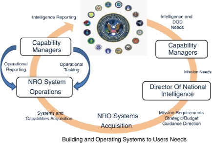
FIGURE C-5 The National Reconnaissance Office’s (NRO’s) capability evaluation and delivery process. SOURCE: Maj Gen Susan Mashiko, Deputy Director, National Reconnaissance Office. “Briefing to the Committee on Examination of the Air Force ISR CP&A Process.” Presentation to the committee, December 8, 2011.
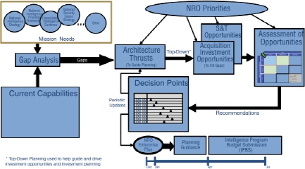
FIGURE C-6 The National Reconnaissance Office’s (NRO’s) integrated architecture and investment planning process. SOURCE: National Reconnaissance Office.
that evaluates alternative solutions based on NRO and operational priorities for informing potential investment decisions. The NRO uses a variety of tools, both commercial off-the-shelf and custom.
RAND CORPORATION
The RAND Corporation uses two main systems engineering tools: the Systems and CONOPS Operational Effectiveness Model (SCOPEM) developed by RAND and the SEAS Modeling Environment maintained and developed by ExoAnalytic Solutions for the Air Force Space Command, Space and Missile Systems Center, Directorate of Development Planning (SMC/XR). SEAS is part of the Air Force Standard Analysis Toolkit and the Air Force Space Command Modeling and Simulation Toolkit (see Figure C-7).
The SCOPEM tool is designed to examine tasking, collection, and targeting decisions within the SEAS Modeling Environment and offers flexible output for the development of measures of performance and/or effectiveness (such as target quality like the National Imagery Interpretability Rating Scale [NIIRS] rating or signal-to-noise ratio and predetermined metrics such as the number of signals intelligence [SIGINT] cues successfully prosecuted in an hour). See Figures C-8 and C-9.
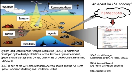
FIGURE C-7 The System Effectiveness Analysis Simulation (SEAS) tool is part of the Air Force Space Command Modeling and Simulation Toolkit used by the RAND Corporation. SOURCE: Lance Menthe, Physical Scientist, RAND Corporation. “The Systems and CONOPS Operational Effectiveness Model (SCOPEM) and Systems Effectiveness Analysis Simulation (SEAS) Modeling Environment.” Presentation to the committee, December 7, 2011.
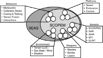
FIGURE C-8 RAND Corporation tool written for the System Effectiveness Analysis Simulation (SEAS) modeling environment. NOTE: The Systems and CONOPS Operational Effectiveness Model (SCOPEM) was formerly known as the Collections Operations Model. SOURCE: Lance Menthe, Physical Scientist, RAND Corporation. “The Systems and CONOPS Operational Effectiveness Model (SCOPEM) and Systems Effectiveness Analysis Simulation (SEAS) Modeling Environment.” Presentation to the committee, December 7, 2011.
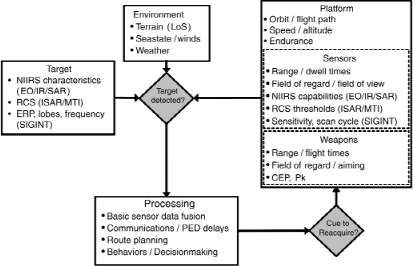
FIGURE C-9 The RAND tool Systems and CONOPS Operational Effectiveness Model (SCOPEM) is designed to examine tasking, collection, and targeting decisions. SOURCE: Lance Menthe, Physical Scientist, RAND Corporation. “The Systems and CONOPS Operational Effectiveness Model (SCOPEM) and Systems Effectiveness Analysis Simulation (SEAS) Modeling Environment.” Presentation to the committee, December 7, 2011.
The utility of this simple tool was illustrated by a series of sensor, weapon, and environment models such as generic sensor models, electro-optical (EO)/ infrared (IR)/synthetic aperture radar (SAR) and electronics intelligence (ELINT) imaging performance estimates, ground moving target indicator (GMTI) tracking models, general weapons models, a missile model, a directed-energy weapon (laser) model, and environmental effects. Four recent examples of SCOPEM/SEAS evaluation scenarios include (1) Global Hawk sensor performance in various maritime operations: MCO-1, MCO-2, and maritime interdiction; (2) air-based and space-based maritime domain awareness in the Mediterranean region; (3) evaluation of F-22 sensor capabilities; and (4) finding, identifying, and tracking of vehicles, using different classes of remotely piloted aircraft, under varied environmental conditions. In summary, SCOPEM is a very accessible, text input-, personal computer/ Windows-based tool by which complex behaviors are built out of simple behaviors and interactions. Like the more complex Multi-Resolution Analysis (MRA) processes advocated by TASC and RadiantBlue, it is a repeatable, transparent, and understandable tool.
U.S. CYBER COMMAND
The U.S. Cyber Command (USCYBERCOM) is a subunified command subordinate to USSTRATCOM. USCYBERCOM centralizes command of cyberspace operations, organizes existing cyber resources, and synchronizes the defense of U.S. military networks.5 USCYBERCOM plans, coordinates, integrates, synchronizes, and conducts activities to direct the operations and defense of specified DoD information networks; and to prepare to and, when directed, conduct full-spectrum military cyberspace operations in order to enable actions in all domains, to ensure U.S./Allied freedom of action in cyberspace, and to deny the same to adversaries. The command is charged with pulling together existing cyberspace resources, creating synergy and synchronizing warfighting effects to defend the information security environment.6 USCYBERCOM is tasked with centralizing the command of cyberspace operations, strengthening DoD cyberspace capabilities, and integrating and bolstering DoD’s cyber expertise. As depicted in Figure C-10, USCYBERCOM requirements range from strategic to operational to tactical requirements, with significant emphasis in the operational to tactical arena owing to the dynamic cyber/ network environment and very short time lines for action and reaction.7
_______
5U.S. Air Force (USAF). 2010. “Cyberspace Operations. Air Force Doctrine Document 3-12.” Available at http://www.fas.org/irp/DoDdir/usaf/afdd3-12.pdf. Accessed February 27, 2012.
6Ibid.
7Everett (Rusty) Rollins, Deputy Director of the Joint Intelligence Operations Center, USCYBERCOM, Directorate of Intelligence (J2). “USCYBERCOM’s Approach to Capability Planning and Analysis for the Cyber Domain.” Presentation to the committee, January 5, 2012.
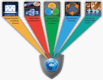
FIGURE C-10 U.S. Cyber Command (USCYBERCOM) requirements for operating in cyberspace. SOURCE: Everett (Rusty) Rollins, Deputy Director of the Joint Intelligence Operations Center, USCYBERCOM, Directorate of Intelligence (J2). “USCYBERCOM’s Approach to Capability Planning and Analysis for the Cyber Domain.” Presentation to the committee, January 5, 2012.
Additionally, USCYBERCOM responsibilities and authorities cross multiple organizations and commands as well as Title 10 (DoD) and Title 50 (IC) to support both offensive and defensive activities.8,9
GOOGLE, INC.
Google was invited to share its capabilities planning process as a potential example of a successful commercial enterprise in a very dynamic, fast-paced, global arena. Interestingly, Google did not present a “process” chart; its investment decisions are based on an evaluation by the company leadership of cost, return
_______
8Ibid.
9The military services and the IC have specific roles and responsibilities, as defined by Title 10 and Title 50 of the U.S. Code, respectively. For additional information on Title 10, see http://uscode.house.gov/download/title_10.shtml. For additional information on Title 50, see http://uscode.house.gov/download/title_50.shtml. Accessed March 21, 2012.
on investment, and probability of success.10 Google is focused on responding to customer needs and on continuing to grow a collaborative environment, and it is perhaps more risk-tolerant than many other organizations.11 Google’s decision processes are expeditious, in keeping with the dynamics of the fast-evolving cloud network and social media arena. Once approved, if an initiative’s measured results fall short of expectations, the activity is generally curtailed, with lessons learned being documented and shared across the company; hence the phrase “Fail fast/ Fail smartly.”12,13
Observations and Attributes
The capabilities planning process at Google is expeditious owing to the company’s “flat” organizational structure, with relatively few decision makers. The culture and operational concept encourage risk taking and are not overly encumbered with deep layers of analysis and recursive iterations. Customer utilization metrics are used effectively to evaluate and inform investment decisions.
NORTHROP GRUMMAN CORPORATION
Northrop Grumman Corporation (NGC) provides system engineering analysis to the U.S. government and consulting services to the ISR community.14 NGC presented several examples of MSA tools that were attributed to work performed by TASC prior to the spin-off of TASC from NGC. The physics-based tool for rapid strategic analysis to guide investment portfolio analysis was identified as a Layered ISR Architecture Analysis (see Figure C-11). This layered analysis process is used to conduct rapid, system-of-systems capabilities-based analysis of air- and space-based ISR systems to identify effective force mix options for DoD and IC needs.15 NGC-described attributes of this process include agility, visibility, flexibility and
_______
10Michele Weslander-Quade, Chief Technology Officer, Google, Inc. “Google’s Approach to Capability Planning and Analysis.” Remarks to the committee, January 5, 2012.
11More information on the Google mission and philosophy is available at http://www.google.com/about/company/tenthings.html. Accessed February 28, 2012.
12Michele Weslander-Quade, Chief Technology Officer, Google, Inc. “Google’s Approach to Capability Planning and Analysis.” Remarks to the committee, January 5, 2012.
13No specific analytic or decision support tools were presented in Google’s remarks to the committee.
14More information on Northrup Grumman Corporation system engineering and analysis projects is available at http://www.northropgrumman.com/about_us/index.html. Accessed February 28, 2012.
15More information on Northrop Grumman’s C4ISR products and programs is available at http://www.northropgrumman.com/isr/index.html. Accessed February 28, 2012.
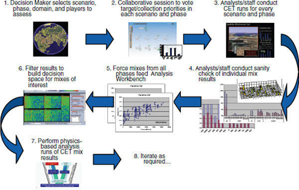
FIGURE C-11 Northrop Grumman Corporation’s (NGC’s) layered intelligence, surveillance, and reconnaissance (ISR) analysis process. SOURCE: Kurt Dittmer, Advanced Programs and Technology, Advanced Projects Director, Northrop Grumman Corporation. “Layered ISR Architecture Analysis, Collection Capability Discussion.” Presentation to the committee, January 5, 2012. Copyrighted material. Used with permission from Northrop Grumman Corporation.
maturity.16The process engages the decision maker early and encourages iterative collaboration among operators and analysts for developing an understanding of system and capability trade-offs.
NGC’s layered ISR process highlighted a top-level ISR force mix assessment tool—the Layered ISR Capabilities Effectiveness Tool (CET)—created by an NGC team of analysts in order to facilitate Long-Range Strategic Plan trade-offs for ISR systems following the 2006 Quadrennial Defense Review (QDR).17This tool was licensed to USSTRATCOM J81 for a proof of principle in 2008 and has been used for studies through a U.S. Joint Forces Command (USJFCOM) ISR Analysis, Integrated Demonstrations and Experimentation Cooperative Research and Development Agreement (CRADA) and is currently being used in support of the Operationally Responsive Space Office and the Missile Defense Agency for capabil-
_______
16Kurt Dittmer, Advanced Programs and Technology, Advanced Projects Director, Northrop Grumman Corporation. “Layered ISR Architecture Analysis, Collection Capability Discussion.” Presentation to the committee, January 5, 2012.
17NGC. 2012. “Layered Intelligence, Surveillance, Reconnaissance (ISR) Architecture Analysis.” Point paper. Written communication to the committee.
TABLE C-1 Description of the Layered ISR Capabilities Effectiveness Tool (CET), with Product and Benefits, Employed by the Northrop Grumman Corporation
| Tool Name | Category | Tool Product | Benefits |
| CET: Layered ISR Capabilities Effectiveness Tool |
Architecture Analysis | Simulation | Top-level ISR force mix assessment tool to guide physics-based analysis. Orders of magnitude faster than current simulation tools. Can be used with many physics-based tools (e.g., STK, EADSIM, BLUESIM). |
NOTE: For a more complete list of tools used by both government and industry, see the full text of Appendix C.
SOURCE: Northrop Grumman Corporation. 2012. Written communication. Response to inquiry from the committee.
ity trade-offs.18 Table C-1 describes the tool employed by NGC and its products and benefits.
The CET is an ISR tool when considering all costs for a specific force mix. Typical inputs from Air Force stakeholders include (1) theater and area of operations; (2) mission domains and phases of war; (3) Commander’s intent (type and quality of required sensor information by target) and target prioritizations; (4) Intel-developed target collection requirements; (5) ISR platforms and satellite constellations, including system performance and sensor capabilities; and (6) system costs. Typical output of the layered ISR tool suite includes (1) all viable force mix solutions; (2) system-of-systems domain, phase, and scenario effectiveness assessment; (3) domain, phase, and scenario capability gaps; (4) system-of-systems costs-effectiveness assessment for life cycle and operations; and (5) optimized orbit locations based on unique system-of-systems solution and platform CONOPS.
In summary, the NGC physics-based analysis layered ISR tool suite was created to improve decision making. It links the commander’s intent (information desired) to results, decisions, and, most significantly, costs. The tool suite has been validated by USSTRATCOMJ-81 through USJFCOM CRADA and is currently being used to support Air Force ORS trade-offs.
__________
18Ibid.
This page intentionally left blank.


