
2
BGCAPP and PCAPP Designs and Relevant Procedures Used at Destruction Facilities
As described in Chapter 1, during the 2002-2003 time frame, the U.S. Department of Defense Assistant Secretary of the Army for Acquisition, Logistics, & Technology (AL&T) issued a number of directives adopting the use of neutralization (chemical hydrolysis) as the primary means for destroying the chemical agent in assembled chemical munitions stored at both the Pueblo Chemical Depot (PCD) in Colorado and the Blue Grass Army Depot (BGAD) in Kentucky.
In brief, the neutralization process entails mixing the chemical agent mustard with hot water or the nerve agents GB and VX with hot caustic solution.1 Under these conditions, the chemical agents react with water, producing hydrolysate products that are less toxic but still require further treatment. At two former sites that only had bulk agent stored in 1-ton containers, neutralization had been used successfully and the Army was able to send the hydrolysate off-site for final treatment. In contrast, at BGCAPP and PCAPP, current plans call for on-site secondary treatment of hydrolysate before the final products can be sent off-site for disposal.
The processes selected by the Army for secondary treatment of hydrolysate are biotreatment at Pueblo and supercritical water oxidation at Blue Grass. These processes are adapted and implemented by the site system contractors and are subject to validation of their effectiveness, budgetary constraints and state regulations.
The disposal processes planned for use at PCAPP and BGCAPP and the waste streams they will produce are described below. More detailed descriptions of the unit operations can be found in prior NRC reports (NRC 2005b, 2005c) and on the ACWA Web site.2
At the time this report was prepared, PCAPP had been issued a Resource Conservation and Recovery Act (RCRA) Research Development and Demonstration (RD&D) permit from the Colorado Department of Public Health and the Environment (CDPHE). BGCAPP has also applied for a RCRA RD&D permit from the Kentucky Department of Environmental Protection.3 In recognition of the significant degree to which the alternative technology designs for the two sites include first-of-a-kind (FOAK)
![]()
1Detailed information on the composition and the chemical and physical properties of the mustard agents (HD, HT) and nerve agents (GB and VX) relevant to ACWA agent destruction activities is presented in Chapter 4 (see Table 4-1 and Figure 4-8).
2The ACWA Web site is at http://www.pmacwa.army.mil/.
3Additional information concerning the PCAPP and BGCAPP permits can be found through the site links at http://www.pmacwa.army.mil/.
equipment and process technologies that have not been previously implemented at full scale, these facilities are designated as pilot plants, i.e., the Pueblo Chemical Agent Destruction Pilot Plant (PCAPP) and the Blue Grass Chemical Agent Destruction Pilot Plant (BGCAPP). However, each facility will have the capacity to destroy the entire chemical weapons stockpile stored at its location. The designs for these facilities have undergone a number of revisions from their original design proposals in 2004, and some downsizing for both technical and budgetary reasons. However, the designs have now been fixed and construction of the two plants is well under way. The RD&D permitting process recognizes the need for flexibility, and negotiations with regulators are ongoing at both sites. Table 2-1 lists the process equipment and machinery at both sites and their potential for being contaminated by agent.
In this chapter, the committee provides background on the safety regulations, procedures, and terminology that are used at chemical destruction facilities. The agent process designs at PCAPP and BGCAPP are also briefly described, followed by a description of the heating, ventilation, and air conditioning (HVAC) systems (the largest source of potentially contaminated activated carbon) common to both plants.
BACKGROUND ON SAFETY PROCEDURES AND REQUIREMENTS USED AT CHEMICAL AGENT DESTRUCTION FACILITIES
The safety procedures and activities related to agent contamination at chemical demilitarization facilities are based on the airborne exposure limits (AELs) that were set by the Centers for Disease Control and Prevention (CDC) in 2003 and 2004 and adopted by the Army, as described in pamphlet DA PAM 385-61, Toxic Chemical Agent Safety Standards (U.S. Army, 2008). The draft document entitled Assembled Chemical Weapons Alternatives (USAE ACWA) Chemical Agent Monitoring Concept Plan, which describes in detail the standards, processes, and procedures for protecting personnel and the public at the two ACWA sites, is the primary reference for the discussion that follows (U.S. Army, 2011a). Types of AELs based on vapor concentrations and duration of inhalation exposure doses are defined and presented for the three relevant chemical agents in Table 2-2. Guidelines from Volume 3 of Acute Exposure Guideline Levels for Selected Airborne Chemicals that were developed as acute exposure guideline levels (AEGLs) for various chemical agents, specifically GB, VX, and mustard agent in this case, are also included in Table 2-2 (NRC, 2003). Both sets of exposure levels are used by the Army.
As briefly mentioned in Chapter 1, the contamination level of waste is often determined by sealing it in a bag or, for large equipment, a plastic “tent” enclosure at 70°F or warmer, for a time sufficient for agent vapor to equilibrate with the waste in the ambient air space. Headspace agent vapor concentrations are then determined by a near- real-time (NRT) agent monitor, such as a miniature continuous air monitoring system (MINICAMS). The Army defines NRT as a measurement cycle of between 5 and 15 minutes. This is a system that provides monitoring for airborne chemical warfare agent using an automated gas chromatograph. The vapor screening levels (VSLs) defined and presented in Table 2-2 typically determine whether the waste can be shipped off-site without further on-site treatment in accordance with site-specific RCRA permit requirements. To be reutilized, an item must meet release levels given in Table 2-3.
TABLE 2-1 Processes and Unit Operations Being Used at PCAPP and BGCAPP
| FOAK | |||
| Equipment | Site(s) | Function | Note |
| Rocker shear machine (RSM) |
BGCAPP | To separate rocket motors from the warhead, drain agent from the warhead, and shear the warhead into small pieces to be sent to the EBHs | This unit will not be contaminated unless a leaking munition contaminates it. |
| Linear projectile mortar disassembly machine(LMPD) | BGCAPP PCAPP | To disassemble projectiles and mortars and remove their bursters | This unit will not be contaminated unless a leaking munition contaminates it. |
| Munitions washout station (MWS) | BGCAPP PCAPP | To remove the burster well from projectiles, drain the chemical agent, and wash out any agent residues | This unit and the room will be contaminated. |
| Energetic bulk hydrolyser EBH) | BGCAPP | To neutralize energetics and any chemical agent in the metal parts of the rockets and fuzes from projectiles | This unit and the explosive containment room will be contaminated. |
| Metal parts treater (MPT) | BGCAPP | To decontaminate projectile bodies and secondary waste by heating to over 1000F for more than 15 min | The front end of this unit will be in a contaminated atmosphere, but the back end, where the metal parts are removed, will not be in a contaminated area. |
| Munitions treatment unit(MTU) | PCAPP | To decontaminate projectile bodies and secondary waste by heating to over 1000°F for more than 15 min | The front end of this unit will be in a contaminated atmosphere, but the back end, where the metal parts are removed, will not be in a contaminated area. |
| Supercritical water oxidation (SCWO) | BGCAPP | To treat agent energetics hydrolysates before releasing them for final disposal | This unit is outside the agent area fence and will be in a noncontaminated area. |
| Immobilized cell bioreactors(ICBs) | PCAPP | To treat mustard hydrolysate before releasing it for final disposal | This unit is outside the agent area fence and will be in a noncontaminated area. |
SOURCE: NRC, 2011.
Vapor screening methods are also used to determine if potentially contaminated workspaces require decontamination during agent changeover or closure activities. In these cases, NRT agent vapor monitors are deployed in unventilated areas to determine if agent vapor levels rise above 1 VSL. While these vapor screening procedures have been used to safely characterize agent contamination of both solid waste materials and structural components at CMA chemical demilitarization sites for the past two decades, they are time consuming and do not directly identify the specific contaminated surface areas that may require further decontamination.
| Agent-Specific Quantities(mg/m3) | ||||
| Exposure Limit Type | Definition | GB | VX | HD |
| Airborne Exposure Limit | ||||
|
General population limit (GPL) |
The concentration limit in which an unprotected general population can be exposed 24 hr/day forever without any adverse effects. Time-weighted average: HD. 12 hr: VX and GB,24br. | lxl06 | 6 x 10⁷ | 2 x 10⁵ |
|
Worker population limit (WPL) (8 hours) |
The concentration at which an unprotected worker can operate safely 8 hr a day for 5 days per week for a working lifetime without adverse effects. Time-weighted average all agents: 8 hours/workday and 40 hour/week for 30 years. | 3 x 10⁵ | lx 106 | 4xl04 |
|
Short term exposure limit (STEL) |
The level at which an unprotected worker can operate for a 15 mm period. The frequency is once per day for HD and VX and four times per day for GB during an 8 hr workday. Time-weighted average: 15 mm. | 1 x l04 | 1 x 10⁻⁵ | 3 x 10³ |
|
Immediately dangerous to life or health limit (IDHL) |
An atmosphere that poses an immediate tlireat to life, would cause irreversible adverse health effects, or would impair the ability to escape from the atmosphere. Also, the maximum level to which an unprotected worker can be exposed for 30 nun without experiencing escape-impairing or irreversible health effects. | 1 x 10⁻¹ | 3 x 10⁻³ | 7 x 10⁻¹ |
| Vapor Screening Level | ||||
|
1VSL |
The concentration of a chemical agent in a headspace below which the materiel can be treated as uncontammated and workers can work with only a slung protective mask. | 1 x l0-4 | 1 x 10⁻⁵ | 3 x 10⁻³ |
| Acute Exposure Guideline Levelsa | ||||
|
1-hrAEGL-l |
The airborne concentration of a substance above winch it is predicted that the general population, including susceptible individuals, could experience discomfort, irritation, or certain asymptomatic nonsensory effects. However, the effects are not disabling and are transient and reversible upon cessation of exposure. | 2.8 x 10⁻³ | 1.7 x 10⁻⁴ | 6.7 x 10⁻² |
| 1.0 x 10⁻³ | 7.1 x 10⁻⁵ | 8.0 x 10⁻³ | ||
|
l-hrAEGL-2 |
The airborne concentration of a substance above winch it is predicted that the general population, including susceptible individuals, could experience irreversible or other serious, long-lasting adverse effects or an impaired ability to escape. | 3.5 x 10⁻² | 2.9 x 10⁻³ | 1.0 x 10⁻¹ |
| 1.3 x 10⁻² | 1.0 x 10⁻³ | 1.3 x 10⁻² | ||
aThe acute exposure guidelines (AEGLs) are a hazard communication measure developed by the National Advisory Committee to establish acute exposure guideline levels for hazardous substances. The committee developed detailed guidelines for devising uniform, meaningful emergency response standards for the general public
SOURCE: Adapted from U.S. Army, 2008; U.S. Army, 2011a; NRC, 2005d.
| TABLE 2-3 Release Levels, Based on AEL Values, for Reuse of Items | ||
| Classification Levela | Vapor Screening Level | Health-Based Risk Analysis Requiredb |
| Contaminated—Do Not Release; specific safeguards required | ≥1 VSL | No |
| Release to Agent Workers Clean—Restricted | <1 VSL | Yes |
| Release to Nonagent Workers Clean—Restricted | <1 WPLc,d | Yes |
| Unrestricted Release to Public (Clean—Unrestricted) | <1 GPLd | Yes |
| Never Contaminated—Clean | N/A | Yes |
aRestrictions may preclude disassembly or applying heat or friction (such as grinding) without special controls.
bHealth-based criteria/risk analyses allow for other methods to be used or developed to determine which classification level applies.
cRestricted—Maintenance or disassembly of items will only be done by personnel knowledgeable in agent symptoms and characteristics, and in facilities equipped with appropriate safeguards to control potential hazards.
dUnrestricted—Items have been previously disassembled and are clean so that they can be released to the worker population without risk of agent release. Release must be in accordance with an approved decontamination plan.
SOURCE: Jeffrey Kiley, CMA, “Monitoring Concepts for Site Closure,” presentation to the 11th International Chemical Weapons Demilitarisation Conference and Exhibition, May 2009.
It is also worth noting that the vapor screening methods described above do not directly measure the amount of chemical agent contaminating solid waste or structural surfaces. Vapor screening detects the gas phase concentrations of the relevant chemical agents, which for significant amounts of neat liquid or solid agent are controlled by the agent’s vapor pressure. Vapor pressures are a function of sample temperature; values at 25°C for the chemical agents relevant to the two ACWA site stockpiles are presented in Chapter 4 (see Table 4-1). Bizzigotti et al. (2009) present temperature-dependent vapor pressure data for these and other common chemical agents. Detecting a gas-phase agent concentration equivalent to its vapor pressure in the headspace of an enclosed space indicates the presence of a reservoir of condensed-phase agent but does not determine how large that reservoir may be. Operationally, that is not an issue since the VSLs are many orders of magnitude lower than agent equilibrium vapor pressures, and so obtaining readings of sub-VSL headspace concentrations is expected to prevent release of any highly contaminated materials containing significant amounts of liquid or solid agent.
However, the measurement of agent vapor levels well below their equilibrium vapor pressures may not always indicate very low material contamination levels, because the effective vapor pressure of any condensed-phase material can be dramatically reduced if the material is dissolved in bulk liquid or surface liquid layers, if it is physically or chemically adsorbed onto solid materials surfaces, and/or if it diffuses into and binds to porous materials (such as activated carbon or concrete). Since the effective vapor pressure of a specific agent at a given temperature depends strongly on the composition,
morphology, and quantity of the solid and/or liquid substrates it encounters, a given equilibrated vapor concentration measurement does not necessarily constitute even a relative measurement of the amount of agent contaminating the condensed-phase materials within the enclosed space. Adamson and Gast (1997) discuss quantitative treatments of vapor adsorption and chemisorption by well-characterized condensed phase surfaces. However, quantitative data for the interactions of chemical agent vapors with real-world, mixed material surfaces are not available.
Finding 2-1. The prevalent Army demilitarization activity methods of detecting materials’ surface contamination involve enclosing materials and monitoring headspace agent concentrations. These are indirect methods that can determine if significant levels of agent are present in the enclosed volume; surfaces are not directly monitored. However, vapor detection does not identify the location or quantify the level of contamination on surfaces within the test volume.
The amount and spatial distributions of chemical agent contaminating secondary waste or structural materials could be determined by direct measurement of adsorbed or chemisorbed agent on their surfaces. Recent advances in analytical technology have greatly simplified the rapid and sensitive measurement of the chemical composition of solid surfaces and matrices. These advances are reviewed and discussed in depth in Chapter 4. Neither CMA nor ACWA has established a health hazard standard for surface adsorbed chemical agents, so no agent surface concentration measurement standards are presented in Table 2-2. However, a recent report from the Centers for Disease Control and Prevention (CDC), which reviewed the chemical agent monitoring programs at the final four CMA demilitarization facilities, specifically recommended that CMA develop a health-based agent hazard level (in milligrams per square meter) for anticipated surface contamination measurements using surface wipe samples on potentially contaminated structural surfaces (CDC, 2010). If such a health hazard standard were to be developed and accepted by relevant regulators, it could be used in conjunction with appropriately calibrated direct surface composition instrumental measurements to determine if secondary waste and structural materials are clean enough to be released for disposal. The CDC suggested that wipe sample evaluations could be used to assess agent contamination on nonporous materials. As discussed in subsequent sections, the newer direct composition measurement technologies may also be able to assess contamination levels of porous materials such as activated charcoal. However, the preparation of accurate agent-contaminated surface calibration standards using appropriate substrates (e.g., concrete, carbon, etc.) is a very challenging task. In the absence of such standards, direct surface contamination measurements will still produce semiquantitative relative distributions of surface contamination, which may nonetheless be valuable guides for material screening and decontamination activities.
Finding 2-2. No CMA or ACWA standards have been established for surface contamination similar to the airborne agent concentration exposure limits, from which vapor screening levels have been adopted. If accepted by the CDC and relevant state regulators, a health-based agent-contaminated surface hazard level measured in mass per unit area by a new, direct surface contamination measurement technology and suitable agent-contaminated surface calibration standards could be useful in clearing secondary waste materials during ACWA disposal operations and/or structural materials during closure. However, reliable agent-contaminated surface calibration standards may be difficult to produce.
In the ACWA facilities, all areas through which munitions pass and where agent could be present at some time will be monitored for airborne agent in NRT using MINICAMS, and archival data will be obtained with Depot Area Air Monitoring System (DAAMS) thermal desorption tubes, which are collected for later gas chromatography/mass spectrometry (GC/MS) analysis in the laboratory. These agent monitoring methods were described in more detail in the NRC report Monitoring at Chemical Agent Disposal Facilities (NRC, 2005a).
Work areas in a chemical agent destruction facility are classified by their likely contamination level using the categories listed in Table 2-4. Worker protection requirements may vary for a given contamination level, depending on the presence of liquid agent and the tasks at hand. The requirements for worker protective clothing and equipment are detailed in Chapter 4 of U.S. Army (2008) and U.S. Army (2011a).
Rooms and corridors adjacent to a Category A or B area are usually classified as Category C. In Category C or D areas, workers must have a protective mask readily available in the event of an accidental agent leak. All workers in Category A areas wear the minimum level of protection required. If liquid agent can be present, then Level A demilitarization protective ensemble (DPE) suits must be worn. The workers are sealed into plastic suits made of 20-30 mil polyvinyl chloride (PVC) that completely enclose them. They don the suits through a slit in the back after which the opening is hermetically sealed by heat. Inside the suit, they also carry on their back a 10-15 minute supply of air to be used in an emergency egress. At waist level, there is a fitting on the DPE suit to attach an umbilical air hose. Workers operate in teams of two in Category A areas. The team is taxied from the DPE donning area to the point where an entry will be made. A third worker in Level B protective ensemble remains outside in the entry vestibule in case of an emergency. As the two workers navigate through the Category A area they plug the end of their air hoses into the nearest air supply valve, one of many that are installed throughout the area. The workers can stay in the area for a maximum of 2 hr (U.S. Army, 2008). Before exiting the area they spray one another with decontamination solution to remove any gross liquid contamination from their DPE suits. Under some conditions, DPE suits are monitored for agent contamination using a MINICAMS detector with a sampling wand to determine if decontamination is complete. DPE suits are removed by cutting them open in the change vestibule. Contaminated suits may be returned to the Category A area for later treatment. These procedures may vary depending on worker condition, site operating procedures, and regulations.
TABLE 2-4 Room Contamination Requirements Using Near-Real-Time Monitoring of the Vapors in the Room
| Category | Definition | Typical Concentrations (AELs) | Typical Rooms with This Category | Required Protective Clothing |
| A | A toxic area supported by a cascade ventilation in system designated for expected chemical agent liquid and/or vapor under normal conditions | IDLH | Toxic areas with agent present and access to the atmosphere, such as munition breaching areas | OSHA-'EPA Level A protection (typically DPE) |
| B | A toxic area supported by the cascade ventilation system designated for expected chemical agent vapor under normal situations but expected chemical agent liquid under off-normal situations. | <1VSL | Explosive containment rooms (ECRs). transfer and holding areas | Typically OSHA/EPA Level A. B, or C protection, depending on work tasks |
| c | An area adjacent to Category A or B areas, that is supported by a cascade ventilation system designated for expected chemical agent vapor under off-normal situations only. Chemical agent liquid is not expected under normal situation or off-normal situation. | <STEL with confirmation monitoring WPL with confirmation monitoring | <Work and process support areas such as the unpack area and observation corridors | Typically OSHA/EPA Level D (with escape mask readily available) |
| D | An area where chemical agent liquid or vapor are not expected under normal or off-normal situations. | <STEL when single contained chemical warfare materiel and personnel present | Facility support areas such as administrative areas and maintenance buildings | No general PPE requirement except to have escape mask readily available |
| E | An area maintained at positive pressure and where chemical agent liquid and vapor are precluded froin entering. | No agent presence | Positive pressure support areas such as the control room and medical facilities. | No general PPE requirement except to have escape mask readily available |
SOURCE: Adapted from U.S. Army, 2011a.
PUEBLO CHEMICAL AGENT DESTRUCTION PILOT PLANT
The chemical munitions stored at the PCD are artillery projectiles and 4.2-in. mortar rounds, all of which only contain mustard, a blister agent, in one of two forms, HD or HT. HD is distilled mustard and HT is a mixture of HD and T, which is essentially a dimer of H that lowers the melting point of the H. The Pueblo stockpile components are detailed in Table 2-5. A simplified flowchart for the destruction process is shown in Figure 2-1. Figure 2-2 is a more detailed flowchart depicting process waste streams and their disposal. Figure 2-3 displays the site map for the facility.
Pallets containing the projectiles will be transported from the depot’s storage igloos to the munitions storage magazine (MSM) at PCAPP. Because munitions can only be transported during daylight hours and in good weather, an accumulation of munitions in the MSM is necessary to ensure round-the-clock operation at PCAPP. The storage igloos will be monitored for agent vapor before the pallets are removed; agent vapor levels will also be monitored in the MSM. Munition pallets will again be monitored for agent vapor before being removed from a transport vehicle after arrival at the unpack area in the enhanced reconfiguration building (ERB). Projectiles containing bursters will be moved to the reconfiguration room (Category B level), where the bursters will be removed by a linear projectile and mortar disassembly (LPMD) machine without disturbing the burster well that seals in the chemical agent. Uncontaminated energetics will be sent offsite for processing. Munitions with agent leaks (leakers) will be overpacked and any agent spills will be documented and decontaminated.
In cases where the burster of a leaker or reject projectile cannot be removed robotically, the entire munition will be disposed of without disassembling using an explosive destruction technology (EDT), an ancillary processing system. There are several types of EDTs, but all involve the destruction of the chemical munitions and their contents by detonation within an enclosed chamber capable of containing the blast. The EDT completely destroys both agents and energetics, reducing them to water, carbon dioxide, and mineral salts. Using an EDT to process problem munitions, such as leakers and rejects, avoids interfering with the higher throughput achievable for processing normal munitions through the main PCAPP facility.4
The reconfigured projectiles will then be transported robotically in munition transfer carts through a long corridor to the agent processing building (APB). In the APB, the munitions, still containing the burster well that seals the agent within the agent cavity of the munition casing, will be moved on trays to the munitions washout system (MWS) in a Category A area. A robot will take a projectile from a tray and place it into one of several cavity access machines (CAMs) in an inverted position. In the CAM, a hydraulic arm will dislodge the burster well by ramming it up into the munition casing and exposing the agent. The agent will then be drained from the munition casing and the interior of the agent cavity will be washed using a high-pressure water wand on the hydraulic arm.
The chemical agent removed from the munition will then be transferred to the agent neutralization system (ANS) area, where it will be neutralized with hot water. Hydrolysate will not be transferred from the ANS until it has been analyzed and verified
![]()
4A leaker is a munition that has leaked agent. A reject is a munition that for any reason cannot be robotically disassembled. For more information on EDTs, see NRC, 2006; 2009a.
TABLE 2-5 Chemical Weapons Stockpile of HD- or HT-Filled Munitions at Pueblo Chemical Depot
| Munition Type | Chemical Fill (kg) |
Energetics Content (kg) |
Configuration |
| 105-mm cartridge, M60 | HD, 1.4 | Burster: tetrytol. 0.12 Fuze: M51A5 Propellant: Ml | Unreconfigured. Complete projectile includes fuze, burster. Propellant loaded with cartridge. Cartridges packed two per wooden box. |
| 105-nini cartridge, M60 | HD, 1.4 | Tetrytol, 0.12 | Reconfigured. Includes burster and nose plug, but no propellant or fuze. Repacked on pallets. |
| 155-nun projectile. mho | HD, 5.3 | Tetrytol, 0.19 | Includes lifting plug and burster but no fuze. On pallets. |
| 155-nun projectile. Ml 04 | HD, 5.3 | Tetrytol. 0.19 | Includes lifting plug and burster but no fuze. On pallets. |
| 4.2-in. mortar. M2A1 | HD, 2.7 | Tetryl. 0.064 Propellant: M8 | Includes propellant and ignition cartridge in a box. |
| 4.2-in. mortar. M2 | HT. 2.6 | Tetryl, 0.064 Propellant: M8 | Includes propellant and ignition cartridge in a box. |
NOTE: The M1 propellant present in 105-mm cartridges that have not been reconfigured (as defined in the column “Configuration”) is present in M67 propelling charges—that is, granular propellant contained in bags as specified in MIL-DTL-60318C.
SOURCE: Adapted from NRC, 2008a.
that at least 99.9999 percent of the agent has been destroyed. The ANS area is classified as Category A and will be contaminated with agent. The area affected by accidental agent spills is minimized by the sumps constructed around the CAMs and any other vessel that contains agent or hydrolysate. Concrete surfaces have a polymer-based coating to help prevent the agent from being absorbed into them.
From this point on in the process, only residual amounts of agent exist in the hydrolysate waste stream. The hydrolysate produced from the neutralization of mustard agent contains thiodiglycol, a major hydrolysis product that must be destroyed to satisfy the Chemical Weapons Convention. The hydrolysate will be transferred to and treated in immobilized cell bioreactors, where bacteria will convert the hydrolysate organic compounds, including thiodiglycol, to water, carbon dioxide, and sludge.5
![]()
5In this context, sludge refers to precipitated solid matter composed of dead microorganisms, insoluble salts, and other low-solubility materials produced during the bioprocessing of mustard agent hydrolysate.
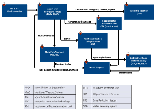
FIGURE 2-1 PCAPP munitions process flow chart. SOURCE: Sean Smith, USAE ACWA Systems Engineering, “PCAPP Overview,” presentation to the committee on February 22, 2011. Note: The numbers above the boxes are simply sequential indicators that complement the arrows and act as guides for the multifaceted destruction progression from box to box.
After the agent and any residual solid heel are removed, the projectile bodies containing the burster wells are placed in other trays and moved to the munitions treatment unit (MTU), where they will be decontaminated by heating to at least 1000°F for over 15 min prior to being released. The MTU is a long, electrically heated muffle furnace with a conveyor that will slowly move projectile bodies from one end to the other as they are treated. The front end of the MTU is in a Category A area, while the back end is contained in a Category C area. The front end of the MTU will be agent contaminated.
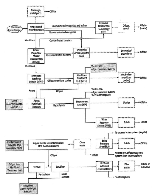
FIGURE 2-2 Process and waste stream diagram for PCAPP. SOURCE: NRC, 2008a.
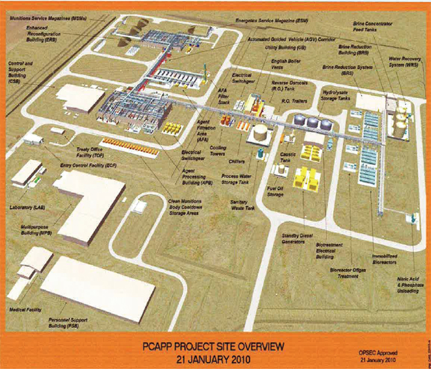
FIGURE 2-3 PCAPP site layout. SOURCE: Sean Smith, USAE ACWA Systems Engineering, “PCAPP Overview,” presentation to the commitee on Febuary 22, 2011.
BLUE GRASS CHEMICAL AGENT DESTRUCTION PILOT PLANT
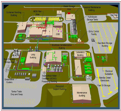
The chemical munitions stockpile stored at BGAD is more diverse than that at the PCD. It includes M55 rockets weaponized with GB or VX nerve agents, and several types of projectiles that contain mustard agent H or GB or VX nerve agents. Consequently, the process for destroying the munitions in the BGAD inventory is more complex than the one at PCAPP. The contents of the stockpile stored at the Blue Grass Army Depot are shown in Table 2-6, and the simplified flowchart for the destruction process is shown in Figure 2-4. Figure 2-5 presents a more detailed flowchart with the waste streams and disposal processes indicated. Figure 2-6 displays the site map for the facility.
The description of the demilitarization process can be separated into two sections: destruction of the projectiles, which is similar to the PCAPP design (and is for that reason not repeated here), and the treatment of the M55 rockets.
The M55 rockets filled with the volatile nerve agent GB will be the first munitions to be destroyed at BGCAPP because they pose the highest storage and processing risks. Each rocket contains about 19 lb of a double-base propellant (approximately 80 percent nitrocellulose and 20 percent nitroglycerine) and 10 lb of GB. The rockets will be transported from storage igloos into the unpack area, where personnel will remove them from the pallets. The rockets will be monitored for agent leaks in the igloos and again after transportation. (Usually, leaks are vaporized agent.) If agent vapor is detected outside the firing tube, the rocket is overpacked and returned to storage for later disposal. Leaker events are documented to inform subsequent decontamination actions.
The rockets, still contained in their fiberglass shipping and firing tubes (SFTs), will be placed on a conveyor and moved to the explosion containment vestibule (ECV) and onto a rocket cutting machine (RCM). First, the propellant motor section at the back end will be separated from the rocket warhead by cutting through the SFT and rocket body with a pipe-cutter-like device. The first cut is only deep enough to cut open the SFT so that it can be removed. Then, the cut will be deepened enough to breach the outer body of the rocket, allowing the warhead and motor sections to be separated. Uncontaminated propellant sections and the two firing tube sections will be shipped off-site for disposal. Up to this point, no agent contamination should exist unless an unexpected event occurs and the warhead is breached. Thus, the ECV is considered a Category B area.
After separation, the rocket warheads will be transferred to a rocket shearing machine in the explosive containment room (ECR). The top and bottom of the rocket will be punctured and the agent is drained. The warhead cavity will then be washed out with a high-pressure (430 psig) water system to remove residual agent as well as any gelled or crystallized material that may have formed during storage. The drained warhead will then be sheared into four segments in the rocket shear machine.
| TABLE 2-6 Description of the Chemical Weapons in the BGAD Stockpile | ||
| Munition Type | Chemical Fill (lb) | Energetics Content (lb) |
| 155-mm projectile, M110 | H, 11.7 | Tetrytol, 0.41 |
| 8-in. projectile, M426 | GB, 14.4 | None |
| 115-mm rocket, M55 | GB, 10.7 | Composition B, 3.2 M28 propellant, 19.1 |
| 115-mm rocket warhead, M56 | GB, 10.7 | Composition B, 3.2 |
| 155-mm projectile, M121/A1 | VX, 6 | None |
| 115-mm rocket, M55 | VX, 10.1 | Composition B, 3.2 M28 propellant, 19.1 |
| 115-mm rocket warhead, M56 | VX, 10.1 | Composition B, 3.2 |
SOURCE: Adapted from NRC, 2008a.
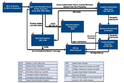
FIGURE 2-4 BGCAPP munitions process flow chart. SOURCE: Darren Dalton, BGCAPP Systems Engineer, ACWA, “BGCAPP Site Project Overview,” presentation to the committee on February 22, 2011. NOTE: The numbers above the boxes are simply sequential indicators that complement the arrows and act as guides for the multifaceted destruction progression from box to box.
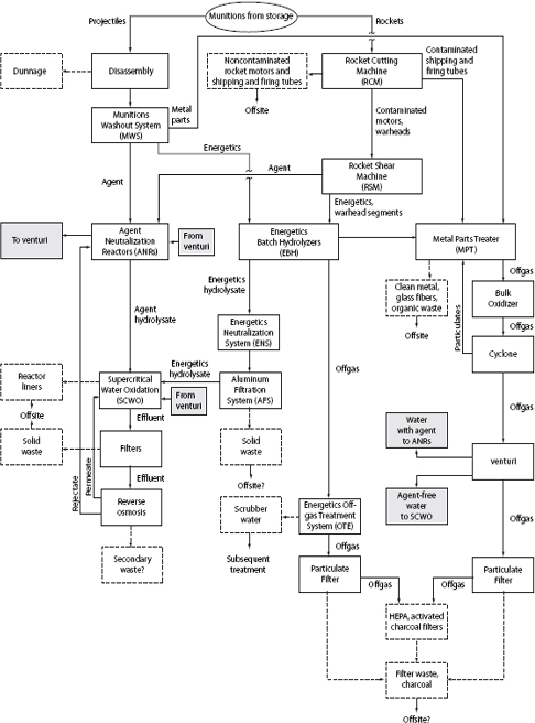
FIGURE 2-5 Process and waste stream diagram for BGCAPP. SOURCE: NRC, 2008a.
BGCAPP Site Plan
January 11, 2008
FIGURE 2-6 BGCAPP site layout. SOURCE: Darren Dalton, BGCAPP Systems Engineer, ACWA, “BGCAPP Site Project Overview,” presentation to the committee on February 22, 2011.
After the reverse assembly (i.e., disassembly) is completed, two process streams are produced (see Figures 2-4 and 2-5):
• Agent for processing in the agent neutralization reactors (ANRs)
• Energetics for treatment in the energetic batch hydrolyzers (EBHs)
Chemical agent drained from the warhead will be transferred into holding tanks associated with the agent collection system. Water from rinsing the warhead will be sent to the holding tank for spent decontamination solution. From the holding tank, the chemical agent and rinse water are sent to an ANR, where the chemical agent will be neutralized. The hydrolysate from the ANR will then be sent for treatment to one of three supercritical water oxidation (SCWO) units, where its organic constituents will be oxidized to water, carbon dioxide, and salts.
After shearing, each rocket segment will be dropped into a bucket. Sheared segments will include the burster and the fuze. The buckets will be conveyed to the EBH room. The three EBHs are large rotating vessels, similar to the drum of a cement mixer truck, that have discontinuous helical flights used to mix the components as the EBH rotates.. Once in the EBH room, a robot will pick up each bucket and raise it to a platform near the top of the EBHs. A second robot will then move the bucket from the platform to an EBH, where the contents are dumped into the EBH. This area will be Category A, susceptible to both liquid and vapor contamination.
Prior to the addition of metal parts and energetics, the EBHs are partially filled with water followed by 50 percent caustic, to produce a concentration of 39.5 percent caustic, then heated to 240°F. After processing the metal parts and energetics for the specified time, the direction of rotation of the EBH drum will be reversed, lifting the metal parts out of the EBH and dropping them onto the vibrating screen belt of a horizontal conveyor. Any liquid will pass through the screen and be collected. When this operation is completed, the rotation speed of the vessel will be increased, allowing the liquid to be removed from the EBH through a wire screen that catches any remaining solids.
The metal parts from the EBH are sent to the metal parts treater (MPT), where they will be decontaminated by heating them with superheated steam to over 1000°F for more than 15 min. After treatment, the metal parts can then be sent off-site for recycling or to a landfill. The hydrolysate from the EBHs will be sent to one of the three energetics neutralization reactors (ENRs), where the neutralization is completed. The contents will remain in the ENR until it has been verified that all energetics and any agent present have been neutralized. The hydrolysate from the EBHs will then be sent to the SCWO units, where the products are oxidized to water, carbon dioxide, and salts. The energetics hydrolysate will be blended with the agent hydrolysate to prevent salt components from potentially solidifying within the SCWO unit; the blending forms a eutectic that lowers the melting point of the blended components below the temperature of the SCWO reactors. The inner liner of the SCWO reactors is made of titanium. For processing the GB blended feed, this liner is scheduled for replacement every 5 weeks, and for the VX blended feed, it will be replaced every 2.6 weeks. For the H blended feed, the liner is not expected to require replacement since the expected replacement interval of 75 weeks for
this feed exceeds the length of time needed for processing the amount of H mustard hydrolysate that would be generated at BGCAPP.
BGCAPP projectile processing will be similar to the processes used at PCAPP. The projectiles will be unpacked manually and conveyed into an ECR, where the bursters will be removed by the two LPMD machines and, if not contaminated, sent to an EBH.6 The munition bodies, still containing their burster wells, will then be moved to the MWS. The projectile bodies will be processed in an MPT instead of an MTU.7 The process from this point on will be identical to the process at PCAPP, described above, except that the hydrolysates will be sent to the SCWO units instead of being sent to bioreactors for treatment.
DESCRIPTION OF THE HVAC SYSTEMS USED AT BOTH FACILITIES
The committee’s statement of task specifically identifies activated carbon as a major secondary waste for which surface monitoring and analysis for agent contamination should be considered. This section briefly describes the uses of activated carbon at BGCAPP and PCAPP, which, in general, are similar to its use at other chemical agent disposal facilities.
The bulk of the activated carbon to be used at BGCAPP and PCAPP resides in the filter banks of the plants’ cascaded HVAC systems. The HVAC system at each site is carefully designed to protect workers, the public, and the environment. Ambient air is circulated through the plant in a cascading manner from areas with no agent contamination to those with low contamination areas and finally to Category B and A areas, where the most contaminated plant air is expected. These latter areas are maintained at the lowest ambient air pressures to prevent backflow to less contaminated areas. More specifically, in the MDB, cascading air passes first through the Category C areas, including the observation corridors, then through the vestibules and airlocks and on to Category B areas, such as the ECR room containing the LPMD, and/or Category A areas, such as the MWS. The ambient air will be constantly monitored using MINICAMS and DAAMS tubes as it proceeds through areas of increasingly reduced atmospheric pressure. Finally, the air moves on to the carbon filter farm and then to the exhaust stack, leaving the plant. The design of the HVAC system for Category E areas such as the process control room, the medical facility, and so on, also accommodates carbon filters
![]()
6If the projectile is a leaker or a reject whose burster cannot be removed by the LPMD machines, it will be overpacked for later disposal processing, possibly by an EDT.
7The MPT is unique FOAK machinery designed for particular application at BGCAPP; the MTU to be used at PCAPP is an adaptation of a metal annealing oven or, as previously indicated, a continuous- belt muffle-type oven with material-handling capabilities at the feed and discharge ends. Additional information concerning the MPT (and the MTU) can be found in NRC (2008b).
installed on the air intakes while providing for the maintenance of positive air pressure within these areas.
The filter farms are identical to those used at the baseline incineration facilities. The description given here is based on a previous NRC report, Disposal of Activated Carbon from Chemical Agent Disposal Facilities (NRC, 2009b). An aerial view of a typical filter farm is depicted in Figure 2-7. A typical farm has eight or nine filter units. Since the operating schedules for PCAPP and BGCAPP are relatively short, it is expected that the carbon will not have to be changed out before closure. Also, at BGCAPP only two units may be used at any one time. Two other units will be used after the first agent disposal campaign is completed. Figure 2-8 shows a side view of a vestibule with the doors leading into the spaces between the individual filter banks. Figure 2-9 is a schematic representation of airflow through a filter unit. The airflow through the unit takes the following path:
1. Through a coarse 85-micron particulate filter to remove large particulates.
2. Through a HEPA filter to remove any remaining particulates.
3. Through six banks of carbon filters with air spaces between them.
4. Through a second HEPA filter to catch any carbon particulates escaping from the carbon filters.
5. Through the large induced-draft fan that drives the whole HVAC system by sucking the air out.
6. Up the exhaust stack and into the atmosphere.
Each filter bank comprises 48 trays weighing about 100 lb each and containing about 48 lb activated carbon. A tray is depicted in Figure 2-10 and the airflow through the tray in Figure 2-11.
MINICAMS monitor the air between banks 1 and 2, 2 and 3, 3 and 4, and 4 and 5, as shown in Figure 2-9. Some variations on these procedures may occur after negotiations with the state regulators. If agent vapor at one STEL (see Table 2-1) were detected between banks 2 and 3, the carbon in banks 1 and 2 would be immediately replaced. Banks 3 through 6 are never likely to be contaminated and can probably be disposed of based on generator knowledge (see Box 2-1), but banks 1 and 2 are likely to be heavily contaminated before breakthrough. It is not expected that the carbon will ever have to be changed during the relatively short operations schedule. The carbon may have to be treated as contaminated waste and be disposed according to the each state’s specific regulations.
The adsorbed agents on the carbon can be analyzed by solvent extraction (EPA, 2007a), followed by GC/MS quantification (EPA, 2007b). Studies indicate that both the nerve agents, GB and VX, and the mustard agent adsorbed on carbon degrade over time at varying rates and through different catalytic pathways involving water vapor, which is also adsorbed onto the carbon (NRC, 2009b). However, without direct analysis, the carbon must be treated as contaminated. A rapid method of scanning the surface to indicate the presence or absence of agent would greatly simplify the disposal process. But its use would have to be approved by state regulators.
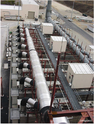
FIGURE 2-7 The nine activated carbon filter units for the MDB HVAC system. SOURCE: NRC, 2009b.
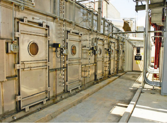
FIGURE 2-8 Vestibule on the side of an MDB HVAC unit. SOURCE: NRC, 2009b.
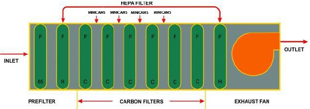
FIGURE 2-9 Schematic representation of airflow through the six filter banks that make up each MDB filter unit. Carbon filters each contain 48 filter trays arrayed in six columns and eight rows with each tray oriented in horizontal position. The 85 indicates 85 percent efficiency for the particulate prefilter; H indicates HEPA filter; F indicates filter; and C indicates carbon filter. SOURCE: Adapted from NRC, 2009b.
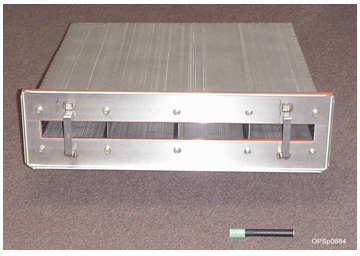
FIGURE 2-10 A filter tray. SOURCE: NRC, 2009b.
Other uses of carbon at BGCAPP and PCAPP involve considerably smaller amounts; however, these uses produce a wide range of contamination levels. For example, activated carbon is used in the canisters in workers’ protective masks. These may or may not become contaminated depending on where and how they are used. Activated carbon is also used in the filters on the venting outlets of the agent collection system (ACS), where agent drained from munitions is collected before neutralization. The ACS carbon is expected to become highly contaminated.
Current methods used to assess agent contamination of machinery, equipment, and waste streams at U.S. Army chemical weapons storage and demilitarization facilities are discussed in more detail in the next chapter.
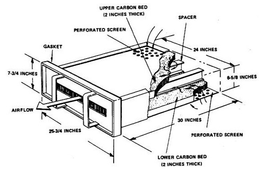
FIGURE 2-11 Airflow path through a filter tray. SOURCE: NRC, 2009b.
BOX 2-1
DEFINITION OF GENERATOR KNOWLEDGE
According to ACWA’s Monitoring Concept Plan document, generator knowledge is defined as follows (U.S. Army, 2011a, p. 56):
Knowledge of the item’s operational and contamination history shall be used to assess and bound the possible agent contamination of a solid or liquid material. The assessment may be based on factors such as location of the item and its proximity to agent in the facility, use in the facility’s operational processes, and worker knowledge of the item’s history. Generator knowledge shall also use supporting records and documents to provide relevant historical details for definitive evidence of contamination assessment. Examples of records for contamination categorization include operational, maintenance, and/or monitoring documents that describe the system associated with the item supported (such as airlock and room agent readings, LSS [life support system] air readings) and any other records that would indicate the potential agent contamination of the item or material.
This page is blank


