

Below is the uncorrected machine-read text of this chapter, intended to provide our own search engines and external engines with highly rich, chapter-representative searchable text of each book. Because it is UNCORRECTED material, please consider the following text as a useful but insufficient proxy for the authoritative book pages.
31 CHAPTER 4 GLOSSARY OF TECHNICAL TERMS The following are the technical terms commonly used in the analysis of wheel and rail interaction. They are listed here to help the reader clarify the physical meaning of each term. Some of them may have been explained in the different sections of the report. They are again listed here for the convenience of reference. Contact Angle The angle of the plane of contact between the wheel and rail relative to the track plane. This should not be confused with the flange angle described below. Contact Stress The force acting per unit area of the contact surface. See Section 3.3. Conicity The ratio of RRD between the left and right wheel over the wheelset lateral displacement: where rL and rR are the rolling radius of the left and right wheel, respectively, and y is the wheelset lateral displacement. Flange Angle The angle between the tangential line of the point on the wheel flange and a horizontal line. The maximum wheel flange angle (δ) is defined as the angle of the plane of contact on the flange relative to the horizontal (see Figure 3.1), This should not be confused with the contact angle described above. Flange Back Clearance The distance between the flange back face of the wheel and the contact face of the restraining rail. Flange Clearance Wheel flange clearance is the wheel lateral shift limit relative to rail prior to wheel climb. See Figure 3.26. Flange Length The total length of the arc or line on the flange of the wheel profile, starting from the point where the maximum flange angle begins to the point where the angle on the flange tip reduces to 26.6 degrees. See Figure 3.2. Gage The distance between the left and right rail measured from the gage point on the rail. The gage point is defined at a specific height below the rail top. Different distances are used by various transit properties. See Figure 3.27. Independently Rotating Wheels A pair of wheels on a common axle that rotate independently of each other without any relative rotational constraint. See Chapter 2 of Appendix B. L/V Ratio The ratio of lateral-to-vertical (L/V) wheel/rail contact forces. Sometimes referred to as the Y/Q ratio. Rolling Contact Fatigue The deformation and damage on a wheel or rail caused by the repetitive experience of excessive normal and tangential forces. Rolling Radius Difference (RRD) The difference in rolling radius between the contact points on the two wheels of a com- mon wheelset. See Figure 3.14. Wheel Back-to-Back Distance The distance between the flange back plane of the left and right wheel. See Figure 3.27. ⬠λ = âr r y L R 2
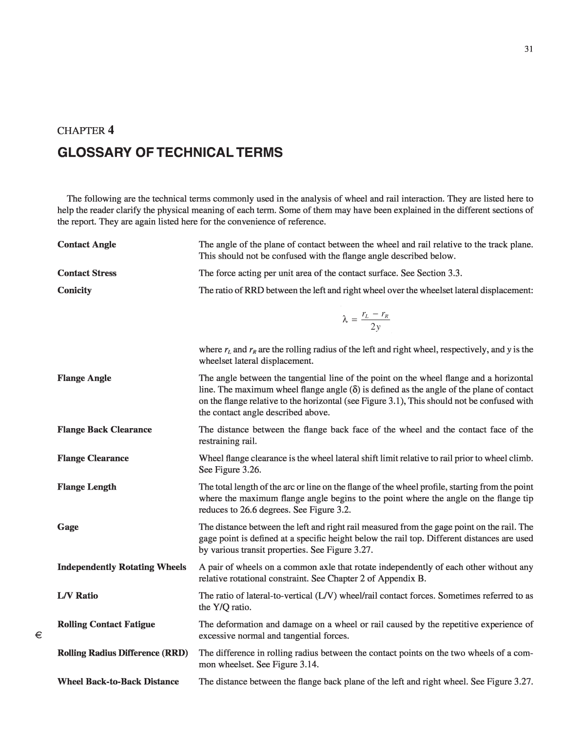
32 Wheelset Angle-of-Attack (AOA) The angle (Ï) between the axis of rotation of the wheelset and a radial line in a curve or a line perpendicular to the track centerline on tangent track, as shown in Figure 4.1. Figure 4.1. Wheelset AOA. V Ï Wheelset Lateral Shift The lateral displacement of the wheelset center relative to the track centerline.
