

Below is the uncorrected machine-read text of this chapter, intended to provide our own search engines and external engines with highly rich, chapter-representative searchable text of each book. Because it is UNCORRECTED material, please consider the following text as a useful but insufficient proxy for the authoritative book pages.
32 A T T A C H M E N T Proposed Method of Test for Measurement of Tire-Pavement Noise Using the On-Board Sound Intensity (OBSI) Method Disclaimer The proposed test method is a recommendation of the NCHRP Project 1-44 staff at Illingworth & Rodkin, Inc., and it includes some modifications to AASHTO Designation Stan- dard TP076-08, Provisional Standard Test Method for the Measurement of Tire/Pavement Noise Using the On-Board Sound Intensity (OBSI) Method. These modifications have not been approved by NCHRP or by any AASHTO Commit- tee or formally accepted for the AASHTO specifications. The research conducted in this project provided a basis for this provisional standard. Proposed Standard Method of Test for Measurement of Tire-Pavement Noise Using The On-Board Sound Intensity Method (OBSI) 1. Scope 1.1 This document defines the procedures for measur- ing tire-pavement noise using the on-board sound intensity (OBSI) method. 1.2 OBSI measurements at the source can be used to characterize the in-service noise performance of pavements. 1.3 This procedure is anticipated to change as experience increases and additional research allows for the estab- lishment of testing variables over a larger data set. 1.4 This standard does not purport to address all of the safety problems, if any, associated with the its use. It is the responsibility of the user of this standard to es- tablish appropriate safety and health practices and determine the applicability of regulatory limitations prior to use. 2. Referenced Documents 2.1 ASTM Standards 2.1.1 F2493 Standard Specification of P225/60R16 Radial Standard Reference Test Tire. 2.2 ANSI Standards 2.2.1 ANSI S1.9-1996 (R2006): Instruments for the Measurement of Sound Intensity. 2.2.2 ANSI S1.40-2006: American National Stan- dard Specifications and Verification Proce- dures for Sound Calibrators. 2.2.3 ANSI S1.11 Specification for Octave-Band and Fractional-Octave-Band Analog and Digital Filters. 3. Terminology 3.1 Sound intensityâThe instantaneous product of acoustic pressure and acoustic particle velocity at a point with direction of propagation defined by the particle velocity vector. It corresponds to the acoustic energy flow through a unit area and the units of Watts per square meter. 3.2 Sound intensity levelâTen times the logarithm of the time averaged sound intensity divided by the ref- erence sound intensity (Iref) of 1 Ã 10â12 watts per square meter [10*Log(I/Iref)]. 3.3 CoherenceâA measure of the linear dependency of two signals with a value of 0 being no dependency, and a value of 1 being perfect linear dependence. Mathematically, it is the magnitude of the cross- spectrum between two signals squared divided by the product of the auto-spectrum of both signals. 3.4 SIindexâThe sound intensity-to-sound pressure level index defined by subtracting the sound intensity level from the sound pressure level. 4. Summary of Methods A method is described in which a sound intensity probe is installed directly on a test vehicle using an appropriate fixture and tire-pavement noise from a standard test tire is measured. Data is acquired over a 440-ft section of pavement at a steady test speed. Where possible, a test speed of 60 mph is used with alternative speeds of 35 and 45 mph depending on
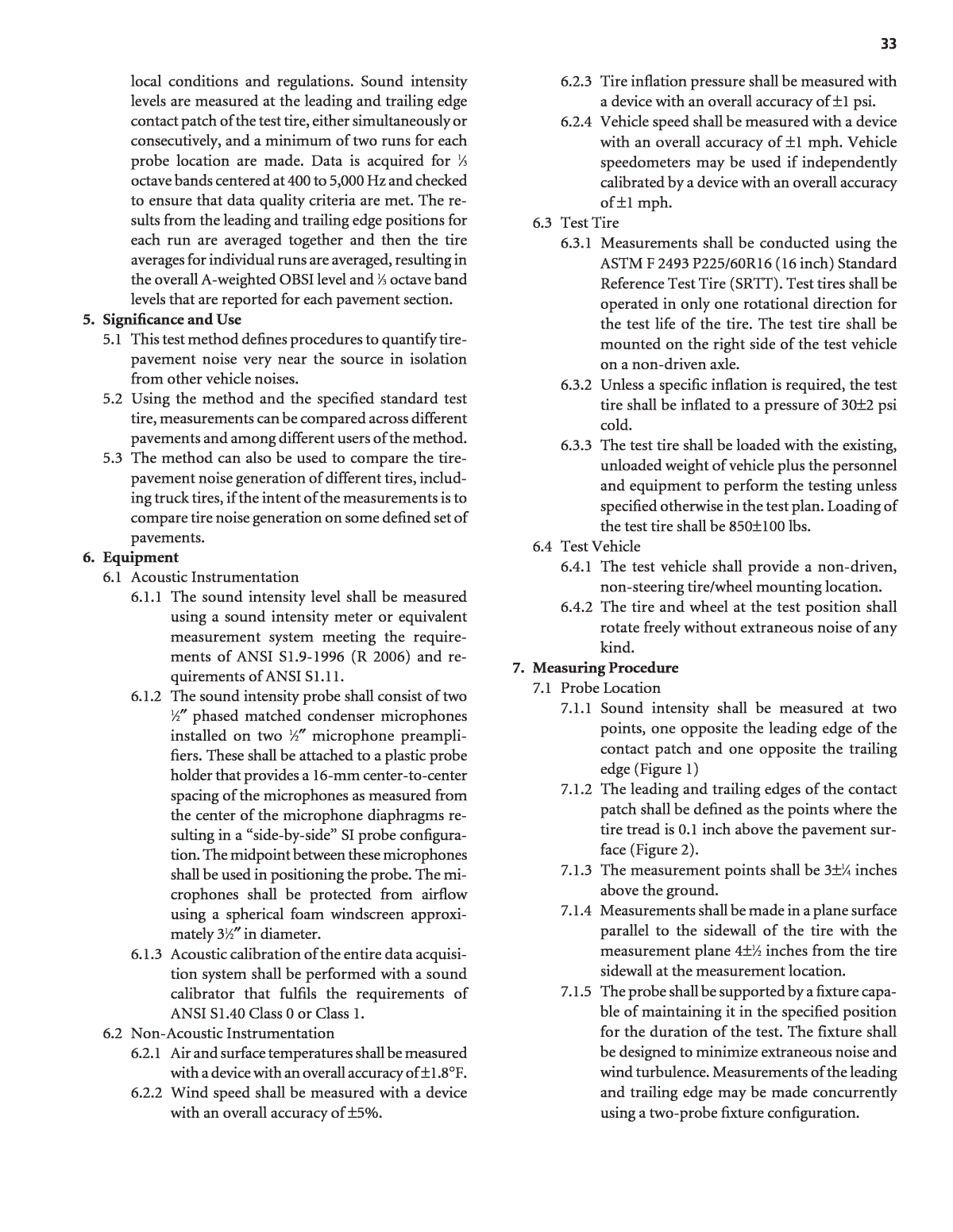
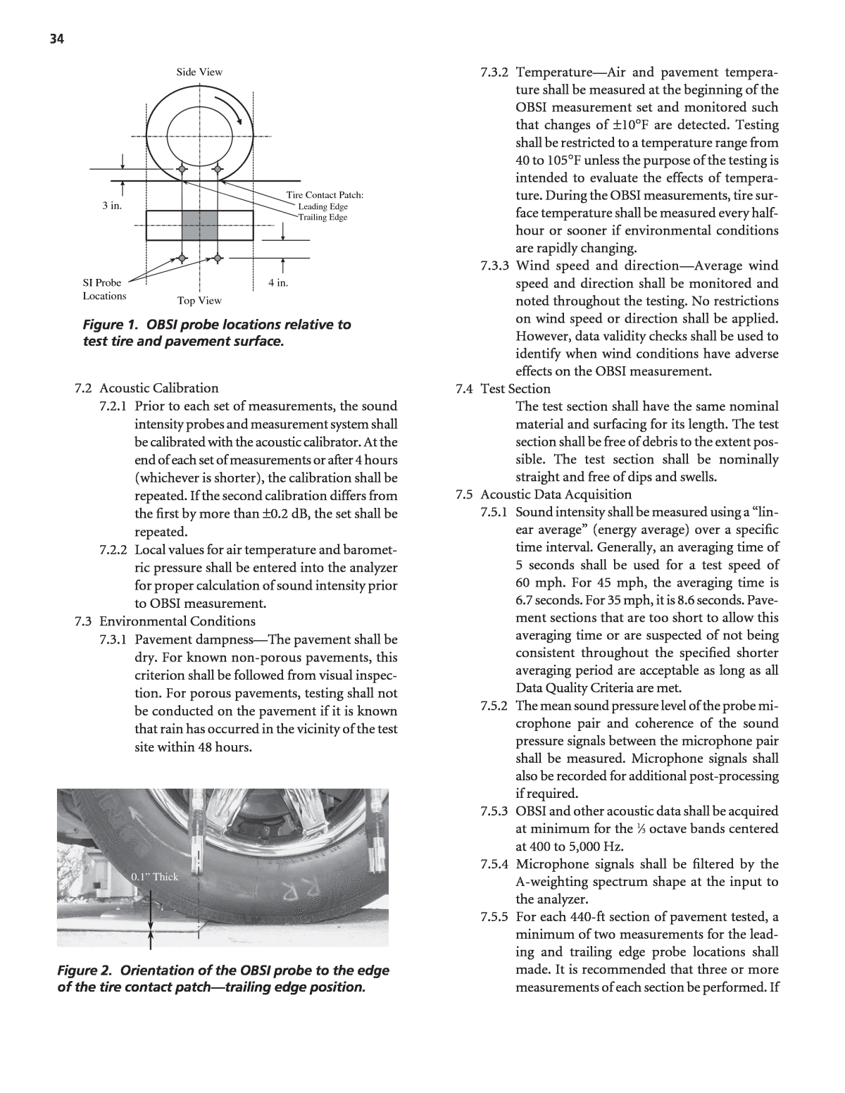
33 local conditions and regulations. Sound intensity levels are measured at the leading and trailing edge contact patch of the test tire, either simultaneously or consecutively, and a minimum of two runs for each probe location are made. Data is acquired for 1â3 octave bands centered at 400 to 5,000 Hz and checked to ensure that data quality criteria are met. The re- sults from the leading and trailing edge positions for each run are averaged together and then the tire averages for individual runs are averaged, resulting in the overall A-weighted OBSI level and 1â3 octave band levels that are reported for each pavement section. 5. Significance and Use 5.1 This test method defines procedures to quantify tire- pavement noise very near the source in isolation from other vehicle noises. 5.2 Using the method and the specified standard test tire, measurements can be compared across different pavements and among different users of the method. 5.3 The method can also be used to compare the tire- pavement noise generation of different tires, includ- ing truck tires, if the intent of the measurements is to compare tire noise generation on some defined set of pavements. 6. Equipment 6.1 Acoustic Instrumentation 6.1.1 The sound intensity level shall be measured using a sound intensity meter or equivalent measurement system meeting the require- ments of ANSI S1.9-1996 (R 2006) and re- quirements of ANSI S1.11. 6.1.2 The sound intensity probe shall consist of two 1â2â³ phased matched condenser microphones installed on two 1â2â³ microphone preampli- fiers. These shall be attached to a plastic probe holder that provides a 16-mm center-to-center spacing of the microphones as measured from the center of the microphone diaphragms re- sulting in a âside-by-sideâ SI probe configura- tion. The midpoint between these microphones shall be used in positioning the probe. The mi- crophones shall be protected from airflow using a spherical foam windscreen approxi- mately 31â2â³ in diameter. 6.1.3 Acoustic calibration of the entire data acquisi- tion system shall be performed with a sound calibrator that fulfils the requirements of ANSI S1.40 Class 0 or Class 1. 6.2 Non-Acoustic Instrumentation 6.2.1 Air and surface temperatures shall be measured with a device with an overall accuracy of ±1.8°F. 6.2.2 Wind speed shall be measured with a device with an overall accuracy of ±5%. 6.2.3 Tire inflation pressure shall be measured with a device with an overall accuracy of ±1 psi. 6.2.4 Vehicle speed shall be measured with a device with an overall accuracy of ±1 mph. Vehicle speedometers may be used if independently calibrated by a device with an overall accuracy of ±1 mph. 6.3 Test Tire 6.3.1 Measurements shall be conducted using the ASTM F 2493 P225/60R16 (16 inch) Standard Reference Test Tire (SRTT). Test tires shall be operated in only one rotational direction for the test life of the tire. The test tire shall be mounted on the right side of the test vehicle on a non-driven axle. 6.3.2 Unless a specific inflation is required, the test tire shall be inflated to a pressure of 30±2 psi cold. 6.3.3 The test tire shall be loaded with the existing, unloaded weight of vehicle plus the personnel and equipment to perform the testing unless specified otherwise in the test plan. Loading of the test tire shall be 850±100 lbs. 6.4 Test Vehicle 6.4.1 The test vehicle shall provide a non-driven, non-steering tire/wheel mounting location. 6.4.2 The tire and wheel at the test position shall rotate freely without extraneous noise of any kind. 7. Measuring Procedure 7.1 Probe Location 7.1.1 Sound intensity shall be measured at two points, one opposite the leading edge of the contact patch and one opposite the trailing edge (Figure 1) 7.1.2 The leading and trailing edges of the contact patch shall be defined as the points where the tire tread is 0.1 inch above the pavement sur- face (Figure 2). 7.1.3 The measurement points shall be 3±1â4 inches above the ground. 7.1.4 Measurements shall be made in a plane surface parallel to the sidewall of the tire with the measurement plane 4±1â2 inches from the tire sidewall at the measurement location. 7.1.5 The probe shall be supported by a fixture capa- ble of maintaining it in the specified position for the duration of the test. The fixture shall be designed to minimize extraneous noise and wind turbulence. Measurements of the leading and trailing edge may be made concurrently using a two-probe fixture configuration.
34 7.3.2 TemperatureâAir and pavement tempera- ture shall be measured at the beginning of the OBSI measurement set and monitored such that changes of ±10°F are detected. Testing shall be restricted to a temperature range from 40 to 105°F unless the purpose of the testing is intended to evaluate the effects of tempera- ture. During the OBSI measurements, tire sur- face temperature shall be measured every half- hour or sooner if environmental conditions are rapidly changing. 7.3.3 Wind speed and directionâAverage wind speed and direction shall be monitored and noted throughout the testing. No restrictions on wind speed or direction shall be applied. However, data validity checks shall be used to identify when wind conditions have adverse effects on the OBSI measurement. 7.4 Test Section The test section shall have the same nominal material and surfacing for its length. The test section shall be free of debris to the extent pos- sible. The test section shall be nominally straight and free of dips and swells. 7.5 Acoustic Data Acquisition 7.5.1 Sound intensity shall be measured using a âlin- ear averageâ (energy average) over a specific time interval. Generally, an averaging time of 5 seconds shall be used for a test speed of 60 mph. For 45 mph, the averaging time is 6.7 seconds. For 35 mph, it is 8.6 seconds. Pave- ment sections that are too short to allow this averaging time or are suspected of not being consistent throughout the specified shorter averaging period are acceptable as long as all Data Quality Criteria are met. 7.5.2 The mean sound pressure level of the probe mi- crophone pair and coherence of the sound pressure signals between the microphone pair shall be measured. Microphone signals shall also be recorded for additional post-processing if required. 7.5.3 OBSI and other acoustic data shall be acquired at minimum for the 1â3 octave bands centered at 400 to 5,000 Hz. 7.5.4 Microphone signals shall be filtered by the A-weighting spectrum shape at the input to the analyzer. 7.5.5 For each 440-ft section of pavement tested, a minimum of two measurements for the lead- ing and trailing edge probe locations shall made. It is recommended that three or more measurements of each section be performed. If SI Probe Locations 4 in. 3 in. Side View Leading Edge Trailing Edge Tire Contact Patch: Top View 0.1â Thick Figure 1. OBSI probe locations relative to test tire and pavement surface. Figure 2. Orientation of the OBSI probe to the edge of the tire contact patchâtrailing edge position. 7.2 Acoustic Calibration 7.2.1 Prior to each set of measurements, the sound intensity probes and measurement system shall be calibrated with the acoustic calibrator. At the end of each set of measurements or after 4 hours (whichever is shorter), the calibration shall be repeated. If the second calibration differs from the first by more than ±0.2 dB, the set shall be repeated. 7.2.2 Local values for air temperature and baromet- ric pressure shall be entered into the analyzer for proper calculation of sound intensity prior to OBSI measurement. 7.3 Environmental Conditions 7.3.1 Pavement dampnessâThe pavement shall be dry. For known non-porous pavements, this criterion shall be followed from visual inspec- tion. For porous pavements, testing shall not be conducted on the pavement if it is known that rain has occurred in the vicinity of the test site within 48 hours.
data quality criteria are not met for at least two of the runs, the measurements shall be re- peated until they are. 7.6 Data Quality Criteria 7.6.1 Audio monitoringâThe sound pressure sig- nals shall be acoustically or visually monitored as they are acquired. Any unusual noises such as rattles, excessive wind noise, stones embed- ded in the tire tread, etc., shall be observed and the cause of such noises shall be identified and remedied. 7.6.2 The direction of the sound intensity shall be positive for all data reported as valid. Positive direction is defined to be sound propagating away from the test tire. 7.6.3 Mean sound pressure level minus sound in- tensity level (SIindex) shall be less than 5 dB and greater than â1 dB in all 1â3 octave bands for all data reported as valid. 7.6.4 CoherenceâThe ordinary coherence between the two microphones constituting the probe shall be greater than 0.8 for all frequencies below 4,000 Hz. 7.6.5 Overall A-weighted sound intensity levels for measurements made of the same pavement section shall be within 1 dBA. The range in sound intensity level between runs shall be less than 2 dB in all 1â3 octave bands for all data re- ported as valid. 8. Data Processing OBSI data shall be processed into levels representing the combination of the noise sources at the leading and trailing edge of the contact patch. If a single probe is used, multiple runs shall be averaged to- gether arithmetically for the leading and trailing edges separately. The leading and trailing averages shall then be averaged on an energy basis. If dual probes are used, the level of the two probes shall be av- eraged on an energy basis for each run. The energy averages for individual runs shall then be averaged together arithmetically. 9. Data Reporting 9.1 The specific acoustic data reported shall depend on the specific needs of the test as defined in the test plan and final report. As a minimum, the following tire-pavement average data shall be reported: overall A-weighted OBSI level summed over the frequency range of valid data with the range noted; 1â3 octave band levels over the range of valid data. 9.2 Any exceptions to this stated OBSI procedure must be reported. 9.3 Other information that shall be reported include air and pavement temperature range during testing, lo- cation and description of the test pavement, the date of the measurement, period of the performance of the measurements, and test speed. 9.4 Additional information to be made available on re- quest shall include wind conditions during the mea- surements, barometric pressure used for air density calculation, coherence, SIindex, probe configuration, and test vehicle make and model. 10. Precision and Bias 10.1 Precision is expected to be within 0.5 dB. 10.2 Bias is expected to be within 1.5 dB. 35
