


Below is the uncorrected machine-read text of this chapter, intended to provide our own search engines and external engines with highly rich, chapter-representative searchable text of each book. Because it is UNCORRECTED material, please consider the following text as a useful but insufficient proxy for the authoritative book pages.
40 This chapter presents the analyses of the data obtained from the measurements on the test sections. These analyses were used to provide a basis for developing a process and detailed sample/guide specifications for selecting texture types. The analyses recognized the limitations of the data (e.g., con- crete and aggregate properties data) and focused on the texture wavelengths because of their reported inï¬uence on pavement friction and noise. As indicated previously, wavelengths fall primarily in the 2-in. (50-mm) and less range and are largely characterized as macro-texture and micro-texture. Friction is highly dependent on the ranges of texture. Micro-texture contributes significantly to friction on dry roads at all speeds and to wet roads at slower speeds. Macro- texture signiï¬cantly inï¬uences friction on wet roads at higher speeds. Therefore, the durability of friction is governed by the polish and abrasion properties of exposed aggregate and by the wear properties of the mix. Noise is mostly a function of macro-texture and the lower wavelength levels of mega-texture. Other factors, such as pavement porosity and stiffness, have been reported to affect noise, but to a much lesser degree. Because the pavements tested in this study were all conventional, low-porosity pave- ments with similar stiffness levels, these factors were not con- sidered in the analyses. Thus, the analysis of noise focused on the inï¬uence of macro- and lower mega-texture characteris- tics (e.g., texture depth, direction, orientation/bias, and spec- trum parameters) and to some extent on the noise inï¬uence of wear properties of the concrete on durability. Chapters 3 and 4 summarized the ï¬eld testing results of existing and newly constructed test sections, respectively. These summaries represent the performance characteristics (quantiï¬cations of texture, friction, and noise levels) of dif- ferent surface textures at a speciï¬c point in time. For a better understanding of the results and to apply them to the devel- opment of a texture selection process, the following detailed data analyses were conducted: ⢠Spectral Analyses â Noise Spectrum AnalysisâIdentiï¬cation of undesirable tonal frequencies (high, medium, and low tones). â Power Spectral Density (PSD) Analysis of TextureâFast Fourier Transform (FFT) to separate the wavelengths and amplitudes of the texture proï¬les into wavebands. â Texture and Noise Spectrum ComparisonsâCross comparisons of texture and noise spectra to identify texture wavelengths with signiï¬cant bearings on noise frequencies. ⢠Comparative/Qualitative Analyses â Comparison of Textures by Site/LocationâDirect/head- to-head comparisons of performance (initial and/or as a function of time/trafï¬c) of textures at individual test sites/locations. â Texture Durability AnalysisâEvaluation of micro- texture and macro-texture durability. â Noise Comparison of TexturesâComparison of noise characteristics by general texture categories and evalua- tion of effects of speciï¬c texture dimensions on noise. â Relationship of Near-Field Noise with Interior and Pass- By Noise. ⢠Statistical Analyses â Texture Depth Measurement ProcedureâCorrelation analysis of texture depth measured using a high-speed proï¬ler and CT Meter. â Test Site/Location Performance AnalysisâAnalysis of variance (ANOVA) and Tukey groupings of texture performance (i.e., texture, friction, and noise) within individual test sites/locations. â National-Level Analysis of Texture, Friction, and Noiseâ ANOVA and regression analysis of texture, friction, noise, and site/location (i.e., trafï¬c, climate, and selected pavement variables) data from all texture test sections. â Noise-Texture RelationshipâMultiple regression analy- sis of texture parameter data (i.e., direction, depth, orien- tation, spectral parameters) and near-ï¬eld SI noise data. C H A P T E R 5 Data Analysis
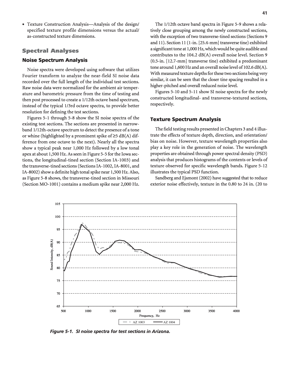
41 65 70 75 80 85 90 95 100 105 500 1000 1500 2000 2500 3000 3500 4000 Frequency, Hz So un d In te ns ity , d B( A) AZ 1003 AZ 1004 Figure 5-1. SI noise spectra for test sections in Arizona. ⢠Texture Construction AnalysisâAnalysis of the design/ specified texture profile dimensions versus the actual/ as-constructed texture dimensions. Spectral Analyses Noise Spectrum Analysis Noise spectra were developed using software that utilizes Fourier transform to analyze the near-field SI noise data recorded over the full length of the individual test sections. Raw noise data were normalized for the ambient air temper- ature and barometric pressure from the time of testing and then post processed to create a 1/12th octave band spectrum, instead of the typical 1/3rd octave spectra, to provide better resolution for deï¬ning the test sections. Figures 5-1 through 5-8 show the SI noise spectra of the existing test sections. The sections are presented in narrow- band 1/12th-octave spectrum to detect the presence of a tone or whine (highlighted by a prominent spike of â¥5 dB(A) dif- ference from one octave to the next). Nearly all the spectra show a typical peak near 1,000 Hz followed by a low tonal apex at about 1,500 Hz. As seen in Figure 5-5 for the Iowa sec- tions, the longitudinal-tined section (Section IA-1003) and the transverse-tined sections (Sections IA-1002, IA-8001, and IA-8002) show a deï¬nite high tonal spike near 1,500 Hz. Also, as Figure 5-8 shows, the transverse-tined section in Missouri (Section MO-1001) contains a medium spike near 2,000 Hz. The 1/12th octave band spectra in Figure 5-9 shows a rela- tively close grouping among the newly constructed sections, with the exception of two transverse-tined sections (Sections 9 and 11). Section 11 (1-in. [25.4-mm] transverse tine) exhibited a signiï¬cant tone at 1,000 Hz, which would be quite audible and contributes to the 104.2 dB(A) overall noise level. Section 9 (0.5-in. [12.7-mm] transverse tine) exhibited a predominant tone around 1,600 Hz and an overall noise level of 102.6 dB(A). With measured texture depths for these two sections being very similar, it can be seen that the closer tine spacing resulted in a higher-pitched and overall reduced noise level. Figures 5-10 and 5-11 show SI noise spectra for the newly constructed longitudinal- and transverse-textured sections, respectively. Texture Spectrum Analysis The ï¬eld testing results presented in Chapters 3 and 4 illus- trate the effects of texture depth, direction, and orientation/ bias on noise. However, texture wavelength properties also play a key role in the generation of noise. The wavelength properties are obtained through power spectral density (PSD) analysis that produces histograms of the contents or levels of texture observed for speciï¬c wavelength bands. Figure 5-12 illustrates the typical PSD function. Sandberg and Ejsmont (2002) have suggested that to reduce exterior noise effectively, texture in the 0.80 to 24 in. (20 to
42 65 70 75 80 85 90 95 100 105 500 1000 1500 2000 2500 3000 3500 4000 Frequency, Hz So un d In te ns ity , d B( A) CA 1002 CA 1003 CA 1004 CA 1045 CA 1005 CA 1007 CA 1075 Figure 5-2. SI noise spectra for test sections in California. 65 70 75 80 85 90 95 100 105 500 1000 1500 2000 2500 3000 3500 4000 Frequency, Hz So un d In te ns ity , d BA CO 3001 CO 3002 CO 3003 CO 3004 CO 3005 CO 3006 Figure 5-3. SI noise spectra for test sections in Colorado.
43 65 70 75 80 85 90 95 100 105 500 1000 1500 2000 2500 3000 3500 4000 Frequency, Hz So un d In te ns ity , d B( A) IL 4001 IL 5001 IL 8001 Figure 5-4. SI noise spectra for test sections in Illinois. 65 70 75 80 85 90 95 105 105 500 1000 1500 2000 2500 3000 3500 4000 Frequency, Hz So un d In te ns ity , d B( A) IA 1002 IA 1003 IA 1004 IA 1061 IA 1007 IA 2001 IA 2002 IA 8001 IA 8002 IA 9002 Figure 5-5. SI noise spectra for test sections in Iowa.
44 65 70 75 80 85 90 95 100 105 500 1000 1500 2000 2500 3000 3500 4000 Frequency, Hz So un d In te ns ity , d B (A ) KS 1002 KS 1004 KS 1005 KS 1006 KS 1007 KS 1008 KS 1010 KS 2001 KS 4001 Figure 5-6. SI noise spectra for test sections in Kansas. 65 70 75 80 85 90 95 100 105 500 1000 1500 2000 2500 3000 3500 4000 Frequency, Hz So un d In te ns ity , d B( A) MN 1001 MN 2003 MN 2004 MN 5001 MN 7001 MN 8001 Figure 5-7. SI noise spectra for test sections in Minnesota.
45 65 70 75 80 85 90 95 100 105 500 1000 1500 2000 2500 3000 3500 4000 Frequency, Hz So un d In te ns ity , d B( A) MO 1001 ND 2001 ND 6001 WI 1001 NC 1001 TX 1001 MI 1001 Figure 5-8. SI noise spectra for test sections in Michigan, Missouri, North Carolina, North Dakota, Texas, and Wisconsin. 65 70 75 80 85 90 95 100 105 500 1000 1500 2000 2500 3000 3500 4000 Frequency, Hz So un d In te ns ity , d B( A) 1aâHeavy Turf Drag (orig) 1bâHeavy Turf Drag (mod) 2âNo Pretexture + 0.75-in Long Tine 3âNo Pretexture + Long Grind 5aâStd Turf Drag + 0.75-in Long Tine 5bâHeavy Turf Drag + 0.75-in Long Tine 6âStd Turf Drag + 0.75-in Shallow Long Tine 7âBurlap Drag + Long Groove 8âStd Turf Drag + Long Groove 9âBurlap Drag + 0.5-in Tran Tine (GA design) 10âBurlap Drag + Random Tran Tine 11âBurlap Drag + 1-in Tran Tine (ISTHA Std) 12âStd Turf Drag + Random Skewed Tine Figure 5-9. SI noise spectra for the newly constructed test sections.
46 65 70 75 80 85 90 95 100 105 500 1000 1500 2000 2500 3000 3500 4000 Frequency, Hz So un d In te ns ity , d B( A) 2âNo Pretexture + 0.75-in Long Tine 3âNo Pretexture + Long Grind 5aâStd Turf Drag + 0.75-in Long Tine 5bâHeavy Turf Drag + 0.75-in Long Tine 6âStd Turf Drag + 0.75-in Shallow Long Tine 7âBurlap Drag + Long Groove 8âStd Turf Drag + Long Groove 1aâHeavy Turf Drag (orig) 1bâHeavy Turf Drag (mod) Figure 5-10. SI noise spectra for longitudinal textures test sections. 65 70 75 80 85 90 95 100 105 500 1000 1500 2000 2500 3000 3500 4000 Frequency, Hz So un d In te ns ity , d B( A) 9âBurlap Drag + 0.5-in Tran Tine (GA design) 10âBurlap Drag + Random Tran Tine 11âBurlap Drag + 1-in Tran Tine (ISTHA Std) 12âStd Turf Drag + Random Skewed Tine Figure 5-11. SI noise spectra for transverse textures test sections.
47 610 mm) wavelength range should be reduced, texture in the 0.08 to 0.40 in. (2 to 10 mm) range should be increased, and the spectrum peak should occur at the lowest wavelengths pos- sible, as illustrated in Figure 5-12. Also, two measures derived from the texture spectrum (L4 and L63) reportedly are good pre- dictors of pavementâtire noise, as illustrated in Figure 5-13 (Sandberg and Ejsmont, 2002). L4 and L63 are deï¬ned as follows: ⢠L4âProï¬le level of the 0.16-in. (4-mm) octave band, rep- resented by an energetic average of the third-octave bands 0.12, 0.16, and 0.20 in. (3.15, 4, and 5 mm); it is associated with high-frequency noise development. ⢠L63âProï¬le level of the 2.48-in. (63-mm) octave band rep- resented by an energetic average of the third-octave bands 2.0, 2.5, and 3.15 in. (50, 63, and 80 mm); it is associated with low-frequency noise development. The texture proï¬le level represented on the y-axis in Fig- ures 5-12 and 5-13 is expressed in decibels relative to a refer- ence RMS value of 1 μm (ISO, 2002). To evaluate the signiï¬cance of texture spectral parameters, the proï¬le data collected on the newly constructed sections (right wheelpath for each 528-ft [161-m] test segment) were processed using the MatLab® PSD software program to obtain texture spectra for each section and compute the L4 and L63 proï¬le levels. Two other PSD parameters were also calculated. ⢠A1âTexture content for the desirable wavelength range of 0.08 to 0.40 in. (2 to 10 mm). ⢠A2âTexture content for the undesirable wavelength range of 0.80 to 24 in. (20 to 610 mm). The corresponding ratios of L4/L63 and A1/A2 were also computed and the locations of the spectrum peaks (in terms 20 30 40 0 10 50 60 Te xt ur e le ve l [ dB re l, 1 m icr o m rm s] Texture Wavelength, mm 2.5640.0 320.0 160.0 80.0 40.0 20.0 10.0 5.0 Mega-texture range Macro-texture range A1A2 Spectrum Peak Figure 5-12. Texture spectrum characteristics for low noise. Figure 5-13. Texture spectrum profile levels.
48 of wavelength) were determined. Table 5-1 summarizes the PSD values obtained for the various textures. The resulting texture spectra showed peaks occurring at considerably lower wavelengths for the heavy turf drag textures and the diamond- ground and groove textures, which were among the quietest textures. Figures 5-14 through 5-16 are plots of near-field SI as functions of L4/L63, A1/A2, and peak spectrum, respectively. These data show a somewhat linear relationship between SI and L4/L63 and between SI and A1/A2. These relationships hold to the principles of reducing higher wavelength tex- ture and increasing lower wavelength texture in order to reduce noise. The three relationships were expected to be limited because noise depends on other factors (e.g., texture depth, direction, and orientation; and pavement porosity and stiffness) besides spectral characteristics. In addition to a relatively small data set, the two-dimensional profile used to represent a three- dimensional proï¬le from which the actual noise was measured also limited the relationship. Comparative/Qualitative Analyses This analysis considers data obtained from the measure- ments on the existing and newly constructed test sections to develop a basic understanding of each textureâs performance characteristics in terms of micro- and macro-texture, friction, and noise. The analysis included the following: ⢠Comparison of textures by site/location. ⢠Texture durability analysis. ⢠Comparison of textures by noise. Texture Description L63 L4/L63 A1 A2 A1/A2 Long Heavy Turf Drag 51 1 411 621 0.66 Long Heavy Turf Drag (mod) 50 0.88 357 667 0.54 Long Tine (0.75-in. spacing, 0.125-in. depth), no pretexture 47 0.74 286 659 0.43 Long DG (no jacks), 0.235-in. spacing (0.11-in. spacers) 50 1.06 428 776 0.55 Long Tine (0.75-in. spacing, 0.125-in. depth), turf drag 44 0.73 258 608 0.43 Long Tine (0.75-in. spacing, 0.125-in. depth), heavy turf drag 39 0.59 193 486 0.40 Long Tine (0.75-in. spacing, 0.075-in. depth), turf drag 47 0.72 277 640 0.43 Long Groove (0.75-in. spacing, 0.25-in. depth), burlap drag 21 1.33 225 322 0.70 Long Groove (0.75-in. spacing, 0.25-in. depth), turf drag 32 1.09 289 464 0.62 Tran Tine (0.5-in. spacing, 0.125-in. depth), burlap drag (GA design) 60 0.85 385 796 0.48 Tran Tine (variable spacing, 0.125-in. depth), burlap drag 52 0.77 308 699 0.44 Tran Tine (1.0-in. spacing, 0.125-in. depth), burlap drag (old ISTHA std) 52 0.75 305 682 0.45 Sect No. 1a 1b 2 3 5a 5b 6 7 8 9 10 11 12 Tran Skew Tine (variable spacing, 0.125-in. depth), turf drag (new ISTHA std) L4 51 44 35 53 32 23 34 28 35 51 40 39 38 47 0.81 310 636 0.49 Peak Spectrum Wavelength, mm 25 30 70 25 50 50 65 15 15 40 45 40 40 Table 5-1. Summary of PSD texture parameters for new test sections. y = -3.8833x + 106.01 R2 = 0.5136 100 101 102 103 104 105 106 0.0 0.2 0.4 0.6 0.8 1.0 1.2 1.4 1.6 L4/L63 N ea r - Fi el d SI , dB (A ) Figure 5-14. Near-field SI noise versus L4 /L63 profile level ratio.
49 ⢠Relationship of near-field noise with interior and pass- by noise. ⢠Texture variability analysis. Comparison of Textures by Site/Location In this analysis, the textures at the different test sites/locations were compared and ranked in terms of their relative perfor- mance as defined by qualitative friction and noise levels. Summary tables were prepared that present the texture, fric- tion, noise, and smoothness results (mean values) for each texture, and the corresponding rankings (1=best, 2=next best, etc.) for friction, noise, and smoothness. Key observations are then made concerning the rankings and overall qualitative performance. The relative rankings of each set of test results are provided in parentheses in the summary tables. In some cases (e.g., Illi- nois Tollway, Colorado US 287), the test results were obtained before opening the road to trafï¬c, thus reï¬ecting an untraf- ï¬cked pavement. In other cases (e.g., Arizona SR 202, Califor- nia SR58), two sets of test results reï¬ecting different levels of cumulative trafï¬c were presented for tests in the wheelpath and at the lane center. In these cases, trafï¬c data (yearly ADT values and truck percentages, estimated directional and lane distribution factors) provided by the respective state DOTs were used to estimate cumulative combined trafï¬c (cars and trucks) and truck trafï¬c applications at time of testing, using the following assumptions: ⢠The right wheelpath (deï¬ned by an 18-in. [460-mm] wide swath) experiences 90 to 95 percent of the combined lane trafï¬c. ⢠The lane center (defined by an 18-in. [460-mm] wide swath), equally spaced between wheelpaths experiences 1 percent of the combined traffic and 0.5 percent of the truck traffic. For evaluating the effect of trafï¬c on the performance of textures, trafï¬c levels were categorized as low trafï¬c (less than 5,000,000 cumulative vehicles and/or less than 500,000 cumu- lative trucks) and high trafï¬c (more than 5,000,000 cumulative vehicles and/or more than 500,000 cumulative trucks). y= -7.1436x + 106.262 R = 0.4467 100 101 102 103 104 105 106 0.00 0.20 0.40 0.60 0.80 1.00 A1/A2 N ea r- Fi el d SI , d B( A) Figure 5-15. Near-field SI noise versus A1/A2 ratio. y = 0.0385x + 101.04 R2 = 0.2913 100 101 102 103 104 105 106 0 10 20 30 40 50 60 70 80 Peak Texture Wavelength, mm N ea r- Fi el d SI , d B( A) Figure 5-16. Near-field SI noise peak texture wavelength.
50 Because there are no established criteria for deï¬ning what is good, fair, and poor with respect to friction and noise, it was necessary to establish and apply some form of criteria to the test results to aid in the development of a texture selec- tion process. Using information from the literature (e.g., Pottinger and Yager, 1986; Wambold, Henry, and Hegmon, 1986; Rasmussen et al., 2007b), the ranges of friction and noise shown in Table 5-2 were identiï¬ed and used as qualitative indicators. Arizona Sections The four diamond-ground sections at this site, located on SR 202L in Phoenix, were constructed in summer 2003 and opened to traffic in fall 2003. Texture, friction, and noise testing was performed approximately 2 years later. The four textures are as follows: ⢠1001âLong DG (no jacks), 0.235-in. (6.0-mm) spacing (i.e., 0.11-in. [2.8-mm] spacers). ⢠1002âLong DG (jacks), 0.235-in. (6.0-mm) spacing (i.e., 0.11-in. [2.8-mm] spacers). ⢠1003âLong DG (no jacks), 0.245-in. (6.2-mm) spacing (i.e., 0.12-in. [3.0-mm] spacers), ï¬ns scraped with motor grader at time of construction. ⢠1004âLong DG (jacks), 0.245-in. (6.2-mm) spacing (i.e., 0.12-in. [3.0-mm] spacers). Table 5-3 summarizes the texture, friction, and noise data collected on these sections, including test measurements made by the state DOT (Scoï¬eld, 2003) at the time of construction. The following are key observations concerning the perfor- mance of these sections (the noise comparisons discussed below are based only on relative rankings associated with each noise parameter [i.e., CPX during construction, SI for low trafï¬c and high trafï¬c]): ⢠In comparison to Section 1002, Section 1004 with wider groove spacing and lower texture depth and TR exhibited lower noise and lower friction. ⢠Section 1003 with the highest texture depth and TR has pro- duced the highest near-ï¬eld and interior noise and highest level of friction, and indicated that smoothness may have some direct effect on noise. ⢠Sections 1003 and 1004 that exhibited the greatest tex- ture deterioration rates (MTD reduction of 0.02 to 0.03 mm per million vehicles [0.1 to 0.58 mm per million trucks]) showed mixed effects on friction and noise (Section 1003 showed no or only slight change in friction and noise, and Section 1004 showed large reduction in friction and only slight change in noise). ⢠Texture, friction, and noise were not noticeably affected by use of jacks. ⢠Noise spectra did not identify tonal issues for any of the textures. California Sections The surface textures on these sections were constructed between fall 2002 and summer 2003. The facility was opened to traffic in fall 2003, and texture, friction, and noise mea- surements were made about 2 years later. These sections are described as follows: ⢠1002âLong DG (no jacks), 0.245-in. (6.2-mm) spacing (i.e., 0.12-in. [3.0-mm] spacers). ⢠1003âLong groove, 0.75-in. (19-mm) spacing, 0.125-in. (3.2-mm) depth, burlap drag. ⢠1004âLong groove, 0.75-in. (19-mm) spacing, 0.25-in. (6.4-mm) depth, burlap drag. ⢠1045âLong burlap drag ⢠1005âLong DG (no jacks), 0.23-in. (5.8-mm) spacing (i.e., 0.105-in. [2.7-mm] spacers). ⢠1007âLong groove, 0.375-in. (9.5-mm) spacing, 0.25-in. (6.4-mm) depth, broom drag. ⢠1075âLong broom drag. Table 5-4 summarizes the texture, friction, and noise infor- mation collected on the sections, including test measurements made at the time of construction by Caltrans (Donavan, 2003). Key observations concerning the performance of these sec- tions are as follows: ⢠Drag-textured sections (1045 and 1075) had the lowest texture depths and generally showed lowest levels of friction. However, the effect of texture depth on noise was inconsistent. Section 1045 with burlap drag texture showed moderate near-ï¬eld and interior noise, and the sections Friction Parameters Noise Parameters Qualitative Designation FN40R FN40S IFI F(60) Near-Field SI, dB(A) Interior Noise Leq, dB(A) Low <35 <28 <28 <102 <69 Moderate 35 to 45 28 to 40 28 to 40 102 to 106 69 to 72.5 High >45 >40 >40 >106 >72.5 Table 5-2. Qualitative designations for friction and noise parameters.
Construction1 Low Traffic (LC)2 High Traffic (WP)3 Texture Smooth Friction Noise Texture Smooth Friction Noise Texture Smooth Friction Noise Sect Design Groove Depth, mm Actual Groove Depth, mm IRI, in./mi RFT Near Field CPX, dB(A) HS EMTD, mm CTM MTD, mm CTM TR IRI, in./mi DFT F(60) Near Field SI, dB(A) Int Leq, dB(A) HS EMTD, mm CTM MTD, mm CTM TR IRI, in./mi DFT F(60) Near Field SI, dB(A) Int Leq, dB(A) 1001 3.2-6.4 â 32.7 (2) 65 (4) 97.5 (3) 0.71 1.07 2.37 (2) 73.2 (2) 41.9 (2) 104.6 (1) 70.3 (1) 0.71 1.04 2.24 (2) 69.4 (1) 41.5 (2) 104.4 (1) 70.4 (2) 1002 3.2-6.4 â 34.2 (3) 66 (3) 98.0 (4) 0.72 1.12 2.41 (3) 80.7 (3) 40.8 (3) 105.6 (3) 71.4 (3) 0.70 1.07 2.27 (3) 80.9 (3) 39.2 (3) 105.8 (3) 72.2 (3) 1003 3.2-6.4 â 28.9 (1) 69 (1) 97.0 (2) 0.92 1.75 2.49 (4) 98.1 (4) 46.4 (1) 0.92 1.56 2.42 (4) 94.0 (4) 47.4 (1) 1004 3.2-6.4 â 38.5 (4) 67 (2) 95.5 (1) 0.73 0.87 1.89 (1) 70.8 (1) 36.5 (4) 104.7 (2) 70.3 (1) 0.64 0.70 1.58 (1) 74.2 (2) 32.2 (4) 104.9 (2) 69.9 (1) 1 in. = 25.4 mm 1 in./mi = 15.78 mm/km 1 Measurements by Arizona DOT. 2 Estimated 58,000 to 93,000 cumulative vehicles (1,600 to 11,000 cumulative trucks). 3 Estimated 5,800,000 to 9,300,000 cumulative vehicles (319,000 to 2,100,000 cumulative trucks). RFT=Runway Friction Tester Note: Values in parentheses represent relative rankings for the respective test parameter. 106.4 (4) 73.5 (4) 106.3 (4) 73.5 (4) Table 5-3. Summary of test results for Arizona SR 202L texture sections.
Construction1 Low Traffic (LC)2 High Traffic (WP)3 Texture Smooth Friction Noise Texture Smooth Friction Noise Texture Smooth Friction Noise Sect Design Groove Depth, mm Actual Groove Depth, mm IRI, in./mi CFT SI, dB(A) HS EMTD, mm CTM MTD, mm CTM TR IRI, in./mi DFT F(60) Near Field SI, dB(A) Int Leq , dB(A) HS EMTD, mm CTM MTD, mm CTM TR IRI, in./mi DFT F(60) Near Field SI, dB(A) Int Leq , dB(A) 1002 1.6-3.2 â â 46.5 (1) 102.3 (6) 0.71 0.96 1.97 (6) 60.5 (2) 40.1 (3) 105.1 (7) 68.8 (2) 0.67 0.67 1.77 (7) 55.1 (1) 68.9 (2) 1003 3.2 â â 42.0 (4) 101.6 (3) 0.80 1.12 0.69 (2) 159.2 (6) 41.4 (2) 104.5 (4) 69.2 (4) 0.76 1.08 0.75 (2) 145.6 (5) 36.7 (2) 105.1 (3) 69.7 (3) 1004 6.4 â â 41.0 (5) 102.0 (4) 1.00 1.31 0.57 (1) 156.7 (5) 44.7 (1) 104.9 (6) 69.5 (5) 0.89 1.29 0.52 (1) 172.7 (6) 38.3 (1) 105.6 (4) 70.3 (5) 1045 â â â â 101.4 (2) 0.63 0.35 1.84 (4) 78.5 (4) 38.2 (5) 104.0 (1) 68.9 (3) 0.63 0.36 1.55 (4) 90.0 (4) 33.1 (4) 104.9 (2) 69.7 (3) 1005 1.6-3.2 â â 45.5 (2) 100.9 (1) 0.67 0.90 2.00 (7) 58.4 (1) 37.7 (6) 104.4 (3) 67.8 (1) 0.64 0.73 1.65 (5) 56.6 (3) 31.9 (6 ) 104.5 (1) 67.9 (1) 1007 6.4 â â 44.0 (3) 102.8 (7) 0.73 1.54 0.86 (3) 64.6 (3) 39.1 (4) 104.7 (5) 70.6 (7) 0.70 1.62 0.88 (3) 56.1 (2) 71.2 (6) 1075 â â â â 102.2 (5) â 0.33 1.89 (5) â 104.3 (2) 70.5 (6) â 0.35 1.65 (5) â 71.5 (7) 1 in. = 25.4 mm 1 in./mi = 15.78 mm/km 1 Measurements by Caltrans. 2 Estimated 36,000 to 54,000 cumulative vehicles (7,000 to 11,000 cumulative trucks). 3 Estimated 3,600,000 to 5,400,000 cumulative vehicles (1,400,000 to 2,100,000 cumulative trucks). CFT=California Friction Tester Note: Values in parentheses represent relative rankings for the respective test parameter. 22.4 (7) 106.2 (5) 32.9 (5) 106.5 (7) 33.7 (3 ) 106.2 (5) 26.0 (7) Table 5-4. Summary of test results for California SR 58 texture sections.
53 with broom drag texture showed a high level of near-field noise. ⢠Diamond-ground sections (1002 and 1005) that had the second lowest texture depths showed differing friction and noise results. The narrower spacing of Section 1005 resulted in the lowest overall near-field and interior noise and one of the lowest levels of friction. The wider spacing of Section 1002 resulted in higher friction and relatively low interior noise, but the highest near-field noise of all sections. ⢠Longitudinal grooved sections (1003, 1004, and 1007) had the highest texture depths and lowest TR values. Friction was highest for the sections with wider spacing textures (1003 and 1004) and lower for the sections with narrower texture spacing (1007). Narrower texture spacing has shown the highest (or nearly highest) near-ï¬eld and interior noise. Although differences were small, the shallower groove depth (0.125 in. [3.2 mm]) and correspondingly lower texture depth of Section 1003 resulted in slightly lower friction and slightly lower noise than that of Section 1004 with the deeper groove depth (0.25 in. [6.4 mm]). ⢠Effect of smoothness on noise was not consistent. The smoothest sections (1002, 1005, and 1007) exhibited the highest and lowest noise levels, and the roughest sections (1003 and 1004) exhibited moderate noise levels. ⢠Diamond-ground Sections 1002 and 1005 showed the great- est texture deterioration rates (MTD of 0.03 to 0.05 mm per million vehicles [0.08 to 0.14 mm per million trucks]); how- ever, friction and noise deterioration rates were generally similar to those of other texture sections. ⢠Noise spectra did not identify tonal issues for any of the textures. Colorado Sections Sections on I-70. These test sections, located near Agate/Deer Trail, were constructed between July and September 1994, and opened to trafï¬c in the OctoberâNovember 1994 timeframe. Texture, friction, and noise measurements were made approx- imately 11 years later, in October 2005. These test sections are described as follows: ⢠1007âLong groove, 0.75-in. (19-mm) spacing, 0.125-in. (3.2-mm) depth, turf drag. ⢠1008âLong turf drag. ⢠1009âLong tine, 0.75-in. (19-mm) spacing, 0.125-in. (3.2-mm) depth, turf drag. Table 5-5 summarizes the texture, friction, and noise infor- mation collected on these sections, including test measure- ments made by Colorado DOT at the time of construction (Ardani and Outcalt, 2005). Key observations concerning the performance of these sections are as follows: ⢠Longitudinal Drag Section 1008 with the lowest texture depth consistently showed the lowest levels of friction and noise with time/trafï¬c. Although F(60) values derived from the DF Tester measurements showed moderate levels of friction in 2005, earlier locked-wheel friction tests by CDOT showed low friction FN40S values for this section. ⢠Longitudinal groove and longitudinal-tine sections (1007 and 1009) had similar texture depths initially, but the section with tine texture exhibited greater reduction in depth with time/trafï¬c. Friction levels over time/trafï¬c for these two tex- tures have been similar. Near-ï¬eld and interior noise has been consistently highest for the longitudinal-tine section. ⢠No effect of smoothness on noise was evident. The smoothest section (1008) exhibited the lowest noise, but the roughest section(1007)exhibited lower noise than the second smooth- est section (1009). ⢠Texture deterioration has been highest for the longitudinal- tine section (1009) with MTD reduction of 0.005 mm per million vehicles (0.01 mm per million trucks) and lowest for the longitudinal groove section (1007). Effects of texture deterioration on friction and noise were not clear. All sec- tions experienced similar friction deterioration rates, and the longitudinal-tine section (1009) experienced the lowest rate of increase in noise. ⢠Noise spectra identified no tonal issues for any of the textures. Sections on US 287. These test sections, located on US 287 near Berthoud, were constructed between fall 2004 and sum- mer 2005. Texture, friction, and noise measurements were made in fall 2005 (long before opening to trafï¬c in June 2006). Descriptions of these test sections are as follows: ⢠3001âLong heavy turf drag. ⢠3002âLong tine, 0.75-in. (19-mm) spacing, 0.1875-in. (4.9-mm) depth, no pretexture. ⢠3003âLong meander tine, 0.75-in. (19-mm) spacing, 0.125-in. (3.2-mm) depth, no pretexture. ⢠3004âLong groove, 0.75-in. spacing (19-mm), 0.125-in. (3.2-mm) depth, turf drag. ⢠3005âLong DG (no jacks), 0.22-in. (5.6-mm) spacing (i.e., 0.095-in. [2.4-mm] spacers). ⢠3006âLong tine, 0.75-in. (19-mm) spacing, 0.125-in. (3.2-mm) depth, turf drag. Table 5-6 summarizes the texture, friction, and noise infor- mation collected on the test sections. Because measurements were made prior to opening of the facility to trafï¬c, an assess- ment of the effects of trafï¬c could not be made. The following
Construction1 Low Traffic (LC)2 High Traffic (WP)3 Texture Smooth Friction Noise Texture Friction Texture Smooth Friction Noise Sect No . Design Groove Depth, mm Actual Groove Depth, mm Sand Patch MTD, mm PI0.2, in./mi FN40R FN40S Near Field SPL, dB(A) Int SPL, dB(A) CTM MTD, mm CTM TR DFT F(60) HS EMTD, mm CTM MTD, mm CTM TR IRI, in./mi DFT F(60) Near Field SI, dB(A) Int Leq, dB(A) 1007 3.2 5.81 1.24 1.7 (1) 53.1 (2) 55.2 (2) 99 (1) 66 (1) 1.30 0.92 (2) 48.4 (1) 1.08 1.41 0.97 (1) 199 (3) 42.8 (2) 105.9 (2) 69.4 (2) 1008 â 0.79 0.51 1.7 (1) 52.0 (3) 30.4 (3) 99 (1) 66 (1) 0.37 1.78 (3) 39.8 (3) 0.67 0.34 1.62 (3) 107 (1) 36.6 (3) 104.4 (1) 68.6 (1) 1009 3.2 3.96 1.19 1.8 (3) 64.4 (1) 56.4 (1) 101 (3) 68 (3) 0.93 1.08 (1) 47.5 (2) 0.98 0.86 1.05 (2) 131 (2) 44.1 (1) 106.1 (3) 69.8 (3) 1 in. = 25.4 mm 1 in./mi = 15.78 mm/km 1Measurements by Colorado DOT. 2Estimated 145,000 cumulative vehicles (30,000 cumulative trucks). 3Estimated 14,500,000 cumulative vehicles (5,900,000 cumulative trucks). SPL = Sound Pressure Level Note: Values in parentheses represent relative rankings for the respective test parameter. Table 5-5. Summary of test results for Colorado I-70 sections.
55 are key observations concerning the performance of these sections: ⢠Sections with the lowest texture depths (3006 [longitudinal- tine-standard groove depth], 3001 [heavy turf drag], and 3005 [longitudinal DG]) exhibited the lowest near-field noise levels and friction values in the mid to low range. ⢠Sections with the highest texture depths (3002 [longitudinal- tine-deeper groove), 3003 [longitudinal meander tine], and 3004 [longitudinal groove]) generally yielded the high- est near-field and interior noise and the highest friction; the exception being the longitudinal groove texture that exhibited the second lowest friction and the second low- est interior noise. ⢠Comparison of Sections 3006 and 3002 (longitudinal-tine with standard and deeper grooves, respectively) indicated the opposite effects of texture depth on friction and noise. Also, Section 3003 (longitudinal meander tine with standard grooves) resulted in higher texture depth than Section 3006. ⢠Higher texture ratios corresponded to lower noise levels. Smoothness may have contributed to this trend, as exhib- ited by Sections 3004 (roughest) and 3005 (smoothest). ⢠Noise spectra identified no tonal issues for any of the textures. Iowa Sections Sections on US 163. The test sections on US 163 near Des Moines were constructed in fall 1993 and opened to trafï¬c in 1994. Texture, friction, and noise measurements were made in August 2005. Descriptions of the test sections are as follows: ⢠1002âTran tine, 0.5-in. (12.7-mm) spacing, 0.075-in. (1.9-mm) depth, turf drag. ⢠1003âLong tine, 0.5-in. (12.7-mm) spacing, 0.075-in. (1.9-mm) depth, turf drag. ⢠1004âLong tine, 0.75-in. (19-mm) spacing, 0.15-in. (3.8-mm) depth, turf drag. ⢠1061âTran groove, 1-in. (25.4-mm) spacing, 0.1875- to 0.25-in. (4.8- to 6.4-mm) depth, turf drag. ⢠1007âLong turf drag. Table 5-7 summarizes the texture, friction, and noise infor- mation collected on the sections, including test measurements made by Iowa DOT at the time of construction (Marks, 1996). Key observations concerning the performance of these textures are as follows: ⢠Comparable texture depths were obtained from the high- speed proï¬ler for the ï¬ve textures. Friction levels on these sections were considerably higher than those for other sec- tions, as indicated by the IFI F(60) values derived from FN40S measurements. ⢠The narrower spacing and shallower depth of the tine pro- ï¬le in Section 1003 yielded slightly lower near-ï¬eld and interior noise levels than that for Section 1004. ⢠The longitudinal turf drag (Section 1007) exhibited low friction values. ⢠The longitudinal turf drag section appeared to be the qui- etest surface initially (for internal noise), but was surpassed by the two longitudinal-tine textures and was assigned a qualitatively âhighâ noise level. ⢠Transverse-tine and groove textures (Sections 1002 and 1061) were assigned qualitatively âhighâ near-ï¬eld noise levels with the latter assigned a qualitatively âhighâ level for interior noise. However, friction levels on both sections were considerably lower than those for the longitudinal- tine sections (1003 and 1004). ⢠All sections exhibited comparable texture depth deterio- ration rates, ranging from 0.006 to 0.009 mm per million vehicles [0.04 to 0.05 mm per million trucks]. Consider- ing the snowfall experienced at this location, a portion of ConstructionâNo Traffic (all measurements based on testing in right wheelpath) Texture Smooth Friction Noise Sect No. Design Groove Depth, mm HS EMTD, mm CTM MTD, mm CTM TR IRI, in./mi DFT F(60) Near Field SI, dB(A) Int L eq , dB(A) Far Field CPB, dB(A) 3001 â 0.93 0.88 1.87 (5) 73.5 (2) 52.4 (3) 103.1 (2) 69.7 (3) 77.8 3002 4.8 0.96 1.03 1.26 (1) 92.6 (4) 54.6 (2) 104.3 (4) 70.4 (5) â 3003 3.2 1.12 1.08 1.36 (2) 84.9 (3) 56.0 (1) 104.4 (6) 71.4 (6) â 3004 3.2 0.80 1.03 1.47 (3) 123.2 (6) 44.4 (5) 104.3 (4) 69.2 (2) 78.6 3005 1.6 0.67 0.91 2.44 (6) 59.7 (1) 43.8 (6) 102.7 (1) 68.1 (1) â 3006 3.2 0.92 0.81 1.51 (4) 98.3 (5) 50.7 (4) 103.8 (3) 69.9 (4) â 1 in. = 25.4 mm 1 in./mi = 15.78 mm/km Note: Values in parentheses represent relative rankings for the respective test parameter. Table 5-6. Summary of test results for Colorado US 287 sections.
Construction1 Low Traffic (LC)2 High Traffic (WP)3 Texture Friction Noise Texture Smooth Noise Texture Smooth Friction Noise Sect No. Design Groove Depth, mm Actual Groove Depth, mm FN40R Int Noise Panel Rating HS EMTD, mm IRI, in./mi Near Field SI, dB(A) Int Leq, dB(A) HS EMTD, mm IRI, in./mi FN40S F(60) Near Field SI, dB(A) Int Leq, dB(A) 1002 1.9 2.25 52 5.7 (4) 1.12 103.4 105.2 (2) 70.7 (1) 0.98 107.3 36.6 (3) 107.6 (4) 71.7 (2) 1003 1.9 2.50 48 2.4 (2) 1.09 118.9 105.3 (3) 71.1 (2) 0.96 113.8 41.4 (2) 105.6 (1) 71.3 (1) 1004 3.8 4.00 49 3.0 (3) 1.09 125.1 105.9 (4) 72.1 (3) 0.96 134.5 43.3 (1) 106.5 (2) 72.3 (3) 1061 4.8-6.4 â â â 1.09 106.8 108.6 (5) 74.1 (4) 1.00 103.9 36.3 (4) 109.4 (5) 74.3 (5) 1007 â â 41 1.6 (1) 1.12 129.0 105.0 (1) 71.1 (2) 1.01 126.6 17.8 (5) 106.6 (3) 73.1 (4) 1 in. = 25.4 mm 1 in./mi = 15.78 mm/km 1Measurements by Iowa DOT. 2Estimated 158,000 cumulative vehicles (12,600 cumulative trucks). 3Estimated 15,800,000 cumulative vehicles (2,500,000 cumulative trucks). Note 1: Values in parentheses represent relative rankings for the respective test parameter. Note 2: Panel rating for interior noise based on 1-to-10 scale (1=unobjectionable, 10=very objectionable) Table 5-7. Summary of test results for Iowa US 163 sections.
57 these texture deterioration rates could be the result of frequent snowplow use. ⢠Sections 1002 and 1003 exhibited definite tonal spikes around 1,500 Hz, indicative of high-frequency whine. Sections on US 34. The test sections on US 34 Bypass north of Mt. Pleasant were constructed in fall 2004. Texture, friction, and noise measurements were made just prior to opening to trafï¬c in fall 2005 (DF Tester and CT Meter testing was per- formed about 6 months later in 2006). The two test sections are described as follows: ⢠2001âLong tine, 0.75-in. (19-mm) spacing, 0.125-in. (3.2-mm) depth), turf drag. ⢠2002âLong tine, 0.75-in. (19-mm) spacing, 0.125-in. (3.2-mm) depth, burlap drag. Table 5-8 summarizes the texture, friction, and noise data collected on the two sections. Some key observations concern- ing the performance of these sections are as follows: ⢠The slightly lower texture depth in Section 2001 appears to have contributed to lower near-ï¬eld and interior noise on this section than on Section 2002. ⢠The more aggressive pre-texturing associated with turf drag on Section 2001 has likely resulted in higher friction levels on this section than on the other. ⢠Smoothness levels of the two sections are very similar, and thus smoothness was not a contributing factor to the dif- ferent levels in noise. ⢠Noise spectra identified no tonal issues for any of the textures. Kansas Sections The test sections on US 69 near Louisburg were con- structed in 2004 and opened to trafï¬c in late 2004. Texture, friction, and noise measurements were made in September, 2005. Descriptions of the seven test sections are as follows: ⢠1002âLong DG (no jacks), 0.235-in. (6-mm) spacing (i.e., 0.11-in. [2.8-mm] spacers), standard-sawed joints. ⢠1004âLong DG (no jacks), 0.245-in. (6.2-mm) spacing (i.e., 0.12-in. [3.0-mm] spacers), single-sawed joints. ⢠1005âLong DG (jacks), 0.255-in. (6.5-mm) spacing (i.e., 0.13-in. [3.3-mm] spacers), standard-sawed joints. ⢠1006âLong DG (jacks), 0.255-in. (6.5-mm) spacing (i.e., 0.13-in. [3.3-mm] spacers), single-sawed joints. ⢠1007âLong DG (no jacks), 0.255-in. (6.5-mm) spacing (i.e., 0.13-in. [3.3-mm] spacers), standard-sawed joints. ⢠1008âLong DG (no jacks), 0.255-in. (6.5-mm) spacing (i.e., 0.13-in. [3.3-mm] spacers), single-sawed joints. ⢠1010âLong tine, 0.75-in. (19-mm) spacing, 0.15-in. (3.8-mm) depth, turf drag. Table 5-9 summarizes the texture, friction, and noise infor- mation collected on the test sections, including measurements made by others (Brennan and Schieber, 2006) at the time of construction. Key observations concerning the performance of these sections are as follows: ⢠The consistently higher texture depths for the four diamond- ground surfaces with 0.13-in. [3.3-mm] spacers resulted in moderately high rankings for friction and moderately low rankings for noise. Despite the low cumulative trafï¬c, nearly all sections reached qualitatively âhighâ levels of interior noise. Speciï¬c comparisons of spacer widths (Section 1002 versus 1007 and Section 1004 versus 1008) show that wider blade spacing contributes to higher texture depth, higher friction, slightly to moderately higher near-ï¬eld noise, higher interior noise, and greater roughness. ⢠The effect of using jacks in the diamond grinding process was not particularly noticeable. Comparisons of Sections 1005 and 1007 and Sections 1006 and 1008 revealed slight Construction (measurements based on testing in right wheelpath, unless indicated differently) Texture Smooth Friction Noise Sect No. Design Groove Depth, mm HS EMTD, mm CTM MTD, mm 1 CTM TR1 IRI, in./mi DFT F(60) 1 FN40S F(60) Near Field SI, dB(A) Int L eq , dB(A) Far Field CPB, dB(A) 2001 3.2 0.80 LC=0.73 WP=0.66 LC=1.27 WP=1.34 88.5 (2) LC=27.8 WP=26.9 52.9 (1) 103.8 (1) 71.5 (1) 78.5 2002 3.2 0.89 LC=0.80 WP=0.71 LC=1.14 WP=1.13 88.0 (1) LC=26.5 WP=26.1 51.1 (2) 105.3 (2) 72.8 (2) 80.5 1 in. = 25.4 mm 1 in./mi = 15.78 mm/km 1Testing with CT Meter and DF Tester performed approximately 6 months after facility opened to traffic. Estimated 750,000 cumulative vehicles applied to wheelpath and 7,500 cumulative vehicles applied to lane center (67,000 and 350 cumulative trucks). Note: Values in parentheses represent relative rankings for the respective test parameter. Table 5-8. Summary of test results for Iowa US 34 sections.
Construction1 Low Traffic (LC)2 High Traffic (WP)3 Texture Smooth Friction Noise Texture Smooth Friction Noise Texture Smooth Friction Noise Sect No. Design Groove Depth, mm Sand Patch MTD, mm Ames LP IRI, in./mi FN40R Near Field SI, dB(A) HS EMTD, mm CTM MTD, mm CTM TR IRI, in./mi DFT F(60) Near Field SI, dB(A) Int Leq , dB(A) HS EMTD, mm CTM MTD, mm CTM TR IRI, in./mi DFT F(60) Near Field SI, dB(A) Int Leq , dB(A) 1002 1.6 1.04 46.0 (6) 49.7 (7) 103.3 (1) 0.62 0.86 2.16 (6) 50.5 (1) 32.9 (7) 104.3 (1) 71.9 (1) 0.64 0.85 2.14 (2) 46.6 (1) 30.2 (7) 105.0 (1) 72.5 (1) 1004 1.6 1.14 37.2 (1) 51.5 (5) 103.5 (2) 0.68 0.85 2.22 (7) 60.5 (3) 34.4 (5) 105.0 (3) 72.6 (3) 0.71 0.88 2.37 (7) 63.5 (5) 32.3 (6) 106.0 (6) 72.5 (1) 1005 1.6 1.32 43.9 (4) 60.7 (1) 105.1 (5) 0.71 1.03 2.11 (3) 63.6 (5) 35.6 (3) 105.0 (3) 72.8 (5) 0.71 1.00 2.14 (2) 60.7 (2) 33.9 (4) 105.6 (4) 72.7 (3) 1006 1.6 1.45 40.1 (3) 57.1 (2) 105.2 (6) 0.69 1.04 2.10 (2) 63.5 (4) 35.3 (4) 105.0 (3) 72.5 (2) 0.72 1.01 2.16 (4) 62.5 (4) 33.2 (5) 105.8 (5) 72.8 (4) 1007 1.6 1.45 37.4 (2) 56.4 (3) 105.0 (4) 0.68 0.99 2.15 (5) 60.0 (2) 33.9 (6) 104.9 (2) 72.6 (3) 0.71 1.10 2.28 (6) 61.6 (3) 34.3 (3) 105.3 (2) 73.3 (5) 1008 1.6 1.30 44.2 (5) 55.1 (4) 104.2 (3) 0.87 0.95 2.12 (4) 96.7 (6) 39.2 (1) 105.9 (7) 73.7 (7) 0.92 1.00 2.23 (5) 99.6 (7) 38.7 (1) 106.9 (7) 74.5 (7) 1010 4.8 0.56 102.6 (7) 50.8 (6) 108.2 (7) 0.64 0.74 1.26 (1) 105.7 (7) 36.3 (2) 105.3 (6) 73.0 (6) 0.66 0.71 1.19 (1) 94.8 (6) 35.6 (2) 105.4 (3) 73.8 (6) 1 in. = 25.4 mm 1 in./mi = 15.78 mm/km CPB Noise Measurements: Sect 1004 (77.8 dB(A)) 1 Measurements by Kansas DOT. 2 Estimated 15,000 cumulative vehicles (1,500 cumulative trucks). 3 Estimated 1,500,000 cumulative vehicles (300,000 cumulative trucks). Three different testing devicesâCA Profilograph, SD Profilometer, and Ames Lightweight Profiler (LP)âwere used to measure smoothness, each giving different results. For consistency purposes, Ames LP IRI measurements are listed. Note: Values in parentheses represent relative rankings for the respective test parameter. Table 5-9. Summary of test results for Kansas US 69 sections.
59 differences in texture depth, small differences in roughness, and small differences in friction that changed over time. The near-ï¬eld and interior noise differences were negligible but the sections on which jacks were used were somewhat quieter than the others. ⢠The effect of joint width (standard 0.375-in. [9.5-mm] wide joint and single-cut 0.125-in. [3.2-mm] wide joint) on noise was also not particularly noticeable. Sections 1005 and 1006 showed similar texture depths and roughness and no apparent differences in near-ï¬eld and interior noise. Sections 1007 and 1008 with 0.125-in. (3.2-mm) wide joints showed somewhat greater noise, but roughness could have been a contributing factor. ⢠The longitudinal-tine Section 1010, which had consis- tently the lowest texture depth, showed the highest level of near-ï¬eld noise initially, but ranked more favorably with time/traffic. Interior noise levels for this texture ranked among the lowest and was qualitatively ranked âhigh.â ⢠TR was not a consistent indicator of noise performance. The longitudinal-tine Section 1010 had the lowest TR, but was among the noisiest sections. The six diamond-ground test sections had very high TR values and moderately high noise levels. ⢠Texture deterioration rates varied from slightly negative deterioration (possibly as a result of pronounced wear by snowplows on the lane center) for three of the diamond- ground sections (1004, 1007, and 1008) to 0.01 to 0.02 mm per million vehicles [0.04 to 0.05 mm per million trucks] for the other three diamond-ground sections and the longitudinal-tine section (Sections 1002, 1005, 1006, and 1010). Although the lack of deterioration for the former three sections contributed to little or no change in friction, noise on these sections increased at similar rates to the other diamond-ground textures. ⢠Noise spectra identified no tonal issues for any of the textures. Minnesota Sections These sections on US 169 near Brooklyn Park were con- structed in 1995 and opened to trafï¬c in late 1995/early 1996. Texture, friction, and noise measurements were made about 10 years later in September 2005. Descriptions of the two test sections are as follows: ⢠7001âLong turf drag. ⢠8001âLong tine, 0.75-in. (19-mm) spacing, 0.125-in. (3.2-mm) depth, turf drag. Table 5-10 summarizes the texture, friction, and noise infor- mation collected on the sections. No measurements were made at the time of construction; however, the sections were included in an earlier study (Kuemmel et al., 2000) and texture, friction, and interior noise data obtained in 1997 have been listed. Key observations concerning the performance of these sections are as follows: ⢠Turf drag Section 7001 exhibited lower texture depth and lower levels of friction and noise with time/trafï¬c than that for the longitudinal-tine Section 8001. Both textures, how- ever, were qualitatively ranked âhighâ for near-ï¬eld noise, and the latter was ranked âhighâ for interior noise. ⢠Friction levels for both surfaces have remained adequate over the 10 years of service. ⢠Although Section 8001 was substantially rougher than Sec- tion 7001, both sections showed similar differences in near- ï¬eld and interior noise levels obtained across test sections (i.e., wheelpath versus lane center). ⢠Texture deterioration rates (as determined by difference in wheelpath and lane center texture depths) were slightly neg- ative for both sections, possibly as a result of wear caused by snowplows. ⢠Noise spectra identified no tonal issues for any of the textures. North Dakota Sections These sections on I-94 Glen Ullin were constructed in Sep- tember 1999 and opened to trafï¬c in late 1999/early 2000. Tex- ture, friction, and noise measurements were made in Septem- ber 2005. Descriptions of the two test sections are as follows: ⢠2001âLong heavy turf drag. ⢠2002âTran tine, variable spacing, 0.1-in. [2.5-mm] depth, turf drag. Table 5-11 summarizes the texture, friction, and noise information collected on these sections, including test mea- surements made by others (Marquart, 2003) at the time of construction. Key observations concerning the performance of these sections are as follows: ⢠The heavy turf drag section (2001) has shown greater tex- ture depth and higher levels of friction and noise with time/trafï¬c than the variably spaced transverse tine (2002). Both surfaces, however, were qualitatively ranked âhighâ for near-ï¬eld noise, and the turf drag surface was ranked âhighâ for interior noise. ⢠Friction levels for both surfaces have remained adequate, likely due to the high-quality aggregate (granite) used. ⢠No effect of smoothness on noise was apparent. ⢠Texture deterioration (as determined by difference between wheelpath and lane center texture depth) has ranged from negligible for the variably spaced transverse tine (Section 2002) to 0.007 mm per million vehicles (0.023 mm per
Construction1 Low Traffic (LC)2 High Traffic (WP)3 Texture Texture Smooth Friction Noise Texture Smooth Friction Noise Sect No. Design Groove Depth, mm HS EMTD, mm CTM MTD, mm CTM TR IRI, in./mi DFT F(60) Near Field SI, dB(A) Int Leq , dB(A) HS EMTD, mm CTM MTD, mm CTM TR IRI, in./mi DFT F(60) Near Field SI, dB(A) Int Leq, dB(A) 7001 â 0.69 0.46 1.52 (2) 79.1 (1) 39.9 (2) 106.3 (1) 71.2 (1) 0.70 0.50 1.42 (2) 78.2 (1) 35.4 (2) 107.3 (1) 71.7 (1) 8001 3.2 0.93 0.95 1.16 (1) 168.2 (2) 46.0 (1) 107.7 (2) 72.5 (2) 0.89 1.00 1.08 (1) 184.9 (2) 41.3 (1) 108.6 (2) 73.1 (2) 1 in. = 25.4 mm 1 in./mi = 15.78 mm/km 1Measurements by Minnesota DOT. 2Estimated 650,000 cumulative vehicles (14,000 cumulative trucks). 3Estimated 6,500,000 cumulative vehicles (2,700,000 cumulative trucks). Note 1: Values in parentheses represent relative rankings for the respective test parameter. Note 2: 1997 test results from Marquette Noise and Texture study include the following: Sect 7001: FN40S=48.8 IRI=64 in./mi ROSANV EMTD = 0.28 mm Int Noise Leq = 68.3 Sect 8001: FN40S=76.6 IRI=67.2 in./mi ROSANV EMTD = 0.77 mm Int Noise Leq = 69.4 Table 5-10. Summary of test results for Minnesota US 169 sections.
Construction1 Low Traffic (LC)2 High Traffic (WP)3 Texture Friction Noise Texture Smooth Friction Noise Texture Smooth Friction Noise Sect No. Design Groove Depth, mm Sand Patch MTD, mm FN40R Int Noise, dB(A) HS EMTD, mm CTM MTD, mm CTM TR IRI, in./mi DFT F(60) Near Field SI, dB(A) Int Leq , dB(A) HS EMTD, mm CTM MTD, mm CTM TR IRI, in./mi DFT F(60) Near Field SI, dB(A) Int Leq, dB(A) 2001 â 0.90 43.0 (1) 68.1 (1) 0.91 0.67 1.23 (1) 80.5 (1) 47.9 (1) 109.8 (2) 72.4 (2) 0.88 0.64 1.21 (1) 93.0 (1) 39.6 (1) 110.8 (2) 73.8 (2) 2002 2.5 1.00 40.2 (2) 69.5 (2) 0.69 0.47 1.78 (2) 81.0 (2) 40.8 (2) 104.8 (1) 68.7 (1) 0.69 0.47 1.76 (2) 98.9 (2) 36.6 (2) 106.2 (1) 69.0 (1) 1 in. = 25.4 mm 1 in./mi = 15.78 mm/km 1 Measurements by North Dakota DOT. 2 Estimated 45,000 cumulative vehicles (6,500 cumulative trucks). 3 Estimated 4,500,000 cumulative vehicles (1,300,000 cumulative trucks). Note: Values in parentheses represent relative rankings for the respective test parameter. Table 5-11. Summary of test results for North Dakota I-94 test sections.
62 million trucks) for the heavy turf drag (Section 2001). Despite no change in texture depth on Section 2002, fric- tion has decreased and noise has increased somewhat. ⢠Noise spectra identified no tonal issues for any of the textures. Illinois Tollway I-355 South Extension Newly Constructed Sections The test sections at the Illinois Tollway were constructed in April/May and September/October 2007 and opened to traf- ï¬c in November 2007. Texture, friction, and noise measure- ments were made 1 to 3 months prior to opening. Texture measurements included tine depth readings taken with a depth gauge (1) during construction, immediately behind the tining machine, (2) after a few weeks of construction trafï¬c, and (3) several weeks after construction and before opening to trafï¬c. Descriptions of the textures are again as follows: ⢠1aâLong heavy turf drag. ⢠1bâLong heavy turf drag (modiï¬ed). ⢠2âLong tine, 0.75-in. (19-mm) spacing, 0.125-in. (3.2-mm) depth, no pretexture. ⢠3âLong DG (no jacks), 0.235-in. (6-mm) spacing (i.e., 0.11-in. [2.8-mm] spacers), no pretexture. ⢠5aâLong tine, 0.75-in. (19-mm) spacing, 0.125-in. (3.2-mm) depth, turf drag. ⢠5bâLong tine, 0.75-in. (19-mm) spacing, 0.125-in. (3.2-mm) depth, heavy turf drag. ⢠6âLong tine, 0.75-in. (19-mm) spacing, 0.075-in. (2-mm) depth, turf drag. ⢠7âLong groove, 0.75-in. (19-mm) spacing, 0.25-in. (6.4-mm) depth, burlap drag. ⢠8âLong groove, 0.75-in. (19-mm) spacing, 0.25-in. (6.4-mm) depth, turf drag. ⢠9âTran tine, 0.5-in. (12.7-mm) spacing, 0.125-in. (3.2-mm) depth, burlap drag (GA design). ⢠10âTran tine, variable spacing, 0.125-in. (3.2-mm) depth, burlap drag. ⢠11âTran tine, 1.0-in. (25.4-mm) spacing, 0.125-in. (3.2-mm) depth, burlap drag (old ISTHA design). ⢠12âTran skewed tine, variable spacing, 0.125-in. (3.2-mm) depth, turf drag (new ISTHA design). Table 5-12 summarizes the texture, friction, and noise infor- mation collected on these sections. Key observations concern- ing the performance of these textures are as follows: ⢠Turf drag sections (1a and 1b) exhibited the lowest texture depths and lowest levels of friction. Near-field noise was relatively low compared with most other surfaces, but interior noise was ranked high. ⢠Longitudinal grooved sections (7 and 8) were among the quietest textures, despite the relatively high texture depths. Negative texture orientation (TR<0.9) may have con- tributed to this phenomenon. The higher texture depth of Section 8 resulted in signiï¬cantly greater friction than for Section 7. ⢠Performance of longitudinal-tine sections (2, 5a, 5b, and 6) varied. The section with the highest macro-texture (Sec- tion 5b), due in part to the heavy turf drag pretexture, had the greatest levels of friction and roughness. Section 5a, which used normal turf drag pretexture, had much lower friction and near-ï¬eld noise, but similar interior noise. Section 2, which included no pretexture, also showed signiï¬cantly less friction and noise. Standard- and shallow- depth longitudinal tining Sections 5a and 6 indicated sim- ilar levels of friction and near-ï¬eld noise, but considerably lower interior noise for the latter. ⢠The diamond-ground Section 3 exhibited the lowest near- ï¬eld and interior noise levels and its texture depth was fourth highest among all sections. ⢠Friction performance of the transverse tine sections was about the same as that for the longitudinal-tine section. The near-ï¬eld noise levels for these textures were somewhat higher than those for the longitudinal, but the interior noise levels were slightly lower. ⢠Two transverse tine sections were found to have signiï¬cant tonal spikes in the noise spectra. Section 9 (Georgia design with 0.5-in. [12.7-mm] spacing) showed a spike around 1,600 Hz, and Section 11 (old ISTHA design with 1.0-in. [25.4-mm] spacing) showed a spike around 1,000 Hz. ⢠Roughness may have contributed to the noise generated by longitudinal-tine on Sections 2 and 5b and by transverse tine on Section 11. General Observations ⢠Diamond Grinding â Jacks versus no jacksâNo notable differences observed at the sites in Arizona and Kansas. â TRâTypical values for diamond-ground sections ranged from 1.5 to 2.5, which exceeded the desirable range (<0.9 to 0.95) for ânegativeâ texture orientation. In gen- eral, a lower TR of the diamond grind texture results in a lower noise level. ⢠Grinding versus GroovingâAlthough texture depths of ground sections in California and Colorado (US 287 [untraf- ï¬cked]) were consistently lower than grooved sections, noise results varied (higher noise on California sites and slightly lower noise on Colorado sites). Friction levels for the ground sections at both locations were slightly lower than that for the grooved sections.
ConstructionâNo Traffic (all measurements based on testing in right wheelpath) Texture Smooth Friction Noise Sect No. Design Groove Depth, mm Groove Depth Behind Tiner, mm Groove Depth After Const Traffic, mm CTM Groove Depth, mm HS EMTD, mm CTM MTD, mm CTM TR PI0.0, in./mi IRI, in./mi DFT F(60) FNS F(60) FNR F(60) Near Field SI, dB(A) Int Leq , dB(A) Far Field CPB, dB(A) 1a â â â â 0.51 â â 21.2 (6) 76 (8) 23.5 (7) â 30.6 (8) 101.7 (3) 69.5 (10) â 1b â â â â 0.59 0.54 1.88 16.3 (1) 63 (3) 21.2 (11) 24.3 (8) 32.1 (5) 101.8 (4) 69.1 (8) 79.3 (6) 2 3.2 3.21 2.63 2.54 0.74 0.65 1.15 22.9 (9) 92 (9) 23.0 (8) 32.8 (6) 30.0 (13) 103.3 (11) 69.5 (10) 79.5 (7) 3 1.5 â â 1.21 0.48 0.74 2.41 20.1 (3) 40 (1) 22.3 (9) â 36.0 (3) 100.6 (1) 67.6 (1) 77.5 (1) 5a 3.2 3.00 2.53 2.69 0.63 0.48 1.27 21.1 (5) 70 (7) 21.6 (10) 35.2 (3) 32.0 (6) 102.5 (6) 71.1 (12) 77.6 (2) 5b 3.2 â â 2.96 1.18 1.05 1.31 27.5 (12) 111 (12) 30.6 (2) 42.7 (1) 30.2 (10) 105.6 (13) 72.0 (13) 82.4 (12) 6 1.9 2.16 1.89 1.94 0.64 0.52 1.33 21.9 (8) 69 (6) 19.5 (13) 34.1 (5) 30.2 (10) 102.3 (5) 68.4 (6) 78.7 (3) 7 6.4 â â 3.61 0.86 0.84 0.73 31.6 (13) 139 (13) 29.4 (3) â 30.1 (12) 101.5 (2) 68.1 (5) 79.1 (5) 8 6.4 â â 5.26 0.99 1.40 0.75 17.9 (2) 106 (11) 36.4 (1) â 36.5 (2) 102.5 (6) 68.0 (4) 78.3 (4) 9 3.2 3.11 2.68 2.08 0.58 0.59 1.57 20.5 (4) 55 (2) 24.0 (4) â 30.6 (8) 102.7 (9) 67.7 (2) 80.7 (10) 10 3.2 3.06 2.50 2.11 0.70 0.71 1.45 25.7 (11) 67 (5) 23.8 (5) 37.2 (2) 39.2 (1) 102.8 (10) 68.8 (7) 81.2 (11) 11 3.2 â â 2.83 0.62 0.50 1.08 25.6 (10) 101 (10) 20.5 (12) 35.2 (3) 32.7 (4) 104.2 (12) 69.3 (9) 80.3 (9) 12 3.2 3.00 2.63 2.37 0.47 0.66 1.42 21.4 (7) 64 (4) 23.8 (5) 28.7 (7) 31.9 (7) 102.5 (6) 67.8 (3) 80.1 (8) 1 in. = 25.4 mm 1 in./mi = 15.78 mm/km Table 5-12. Summary of test results for Illinois Tollway newly constructed test sections.
64 ⢠Grinding versus Longitudinal TiningâDiamond-ground sections in Colorado (US 287 [untrafï¬cked]) and Kansas have resulted in lower levels of friction and interior noise regardless of the texture depth than the longitudinally tined sections. Near-ï¬eld noise levels for the ground sections have ranged from considerably lower to slightly higher than the tined sections. ⢠Grooving versus Longitudinal TiningâColorado I-70 and US 287 (untrafï¬cked) sections showed a slight increase in texture depth of grooved textures resulting in similar to lower levels of friction, slightly lower interior noise, and slightly lower to slightly higher near-ï¬eld noise. ⢠Turf, Broom, and Burlap DragsâThese textures will incur friction problems and may develop noise issues, if high tex- ture is not provided and/or high-quality aggregate is not used. If studded tires are not used, drag textures generally provide the lowest texture deterioration rates under trafï¬c, and possibly under snowplows. ⢠Effect of Smoothness on NoiseâMost sections exhibited high or moderately high levels of smoothness (IRI less than 90 to 100 in./mi), but the effect of roughness could not be determined. ⢠One longitudinal-tine section located in Iowa and transverse tine textures with two 0.5-in. (12.7-mm) spacing designs and shallow or standard depths (Iowa Section 1002 and Mis- souri Section 1001, respectively) and two 0.75-in. (19-mm) spacing designs with standard depths (Iowa Sections 8001 and 8002) were found to have notable tonal issues. Texture Durability Analysis Micro-Texture Deterioration Figure 5-17 provides an indication of the durability of micro-texture for the different sites/locations, based on DFT(20) friction values obtained by the DF Tester in the wheelpath and lane center. Best-fit logarithmic functions were derived to determine the trends as a function of trafï¬c (by state). Although the number and types of textures at each site are not the same, and the type(s) of aggregate used in the concrete mix were not known for all sites, the data illustrate the importance of using high-quality aggregate to maintain high levels of friction over time/trafï¬c. For instance, in Colorado where high-silica granite was used and in Minnesota where a granite was also used, the initial average DFT(20) values were high and remained high under large amounts of trafï¬c. Use of limestone in Kansas and Illinois, on the other hand, has resulted in greater rates of micro-texture deterioration. Based on the available information concerning the types of aggregates that were used in the concrete at the various sites/locations, it is apparent that use of higher quality aggre- (M N) DFT (20) = -2.2786Ln(T raf) + 77.38 3 (M O) DFT(20) = -1.4136 Ln(Traf) + 64. 977 (N D) DFT(20) = -2.487 6Ln(Traf) + 75 .058 (A Z) DFT (20) = -0.9548Ln(T raf) + 76.23 9 (C O) DF T(20) = -1. 6367Ln (Traf) + 76.613 (I L) DFT (2 0) = -3.7523Ln(T raf) + 71.15 1 (KS ) DFT (2 0) = -0.7385L n(Traf) + 62. 082 (CA ) DF T(20) = -2. 9996Ln (Traf) + 68.499 (T X) DF T(20) = -1. 0604Ln (Traf) + 47.066 (W I) DFT (20) = -1.0564L n(Traf) + 78.69 1 40. 0 45. 0 50. 0 55. 0 60. 0 65. 0 70. 0 75. 0 80. 0 85. 0 90. 0 0 10 20 30 40 60 50 70 Cumulative Traffic, million vehicles D FT (20 ) AZ SR202L CA SR58 CO I-70 IL I-55/74 KS US69 MN US169 MO US36 ND I-94 TX I-20 Wi US151 Log. (MN US169) Log. (M O US36) Log. (ND I-94) Log. (AZ SR202L) Log. (C O I-70) Log. (IL I- 55/74) Log. (KS US69) Log. (CA SR58) Log. (T X I-20) Log. (W i US151) CO (fine agg) High -silica granite IL (f ine agg) Ble nd of ma nufactur ed sand (limestone) and natural san d KS (coarse agg) Limeston e MN (fine agg) Granite Figure 5-17. Micro-texture versus cumulative combined traffic.
65 (AZ) MTD = â 0.0328Ln(Traf) + 1.5888 R 2 = 0. 055 (C A) MT D = -0 . 0499L n( Tr a f) + 1. 4742 R 2 = 0. 9363 (KS) MTD = 0.0043Ln(Traf) + 0.911 6 R 2 = 0. 01 54 0.00 0.20 0.40 0.60 0.80 1.00 1.20 1.40 1.60 1.80 2.00 20 5 0 10 15 25 30 35 40 Cumulative Traffic, million vehicles C TM M TD , m m AZ SR 202L CA SR 58 KS US 69 Lo g. (A Z SR 202L ) Lo g. (C A SR 58) Lo g. (K S US 69) Figure 5-18. Macro-texture versus cumulative combined traffic for diamond-ground sections. (CA) MTD = â 0.005Ln(Traf) + 1.3916 R 2 = 0. 0033 (CO) MTD = 0.0239Ln(Traf) + 1.0162 R 2 = 1 0.00 0.20 0.40 0.60 0.80 1.00 1.20 1.40 1.60 1.80 0 5 10 15 20 25 30 35 40 Cumulative Traffic, million vehicles C TM M TD , m m CA SR 58 CO I -70 Lo g. (C A SR 58 ) Lo g. (C O I -70 ) Figure 5-19. Macro-texture versus cumulative combined traffic for longitudinal grooved sections. gates in the concrete mixture helps to maintain the micro- texture qualities needed for friction. Macro-Texture Deterioration Figures 5-18 through 5-23 show the rates of deterioration in macro-texture for the different texture types based on CT Meter MTD values (or in some cases, high-speed profiler EMTD values) taken in the wheelpath and lane center. Best- ï¬t logarithmic functions were derived for each data set. These ï¬gures illustrate the reduction in texture depth for each texture type. With the exception of some of the sections in Kansas, which showed greater texture depth in the wheelpath than in the lane center (possibly because of wear caused by
66 (IL) MTD = -0.0128Ln(Traf) + 1.0457 R2 = 0.0452 (IA) MTD = -0.017Ln(Traf) + 1.2563 R2 = 0.3175 (MO) MTD = -0.013Ln(Traf) + 0.8636 R2 = 1 (WI) MTD = â 0.0261Ln(Traf) + 1.2054 R2 = 1 (ND) MTD = â 0.0083Ln(Traf) + 0.806 R2 = 0.1433 0.00 0.20 0.40 0.60 0.80 1.00 1.20 0 5 10 15 20 25 30 35 40 Cumulative Traffic, million vehicles CT M M TD o r H S E M T D , m m IL I-55/74 & I-70 IA US 163 & US 218 MO US 36 WI US 151 ND I-94 Log. (IL I-55/74 & I-70) Log. (IA US 163 & US 218) Log. (MO US 36) Log. (WI US 151) Log. (ND I-94) Figure 5-20. Macro-texture versus cumulative combined traffic for transverse tine sections. (CO) MTD = -0.0152Ln(Traf) + 1.1106 R2 = 1 (IA) MTD = â 0.0261Ln(Traf) + 1.4019 R2 = 0.9863 (KS) MTD = â 0.0065Ln(Traf) + 0.8026 R2 = 1 (MN) MTD = â 0.0184Ln(Traf) + 1.2812 R2 = 0.269 0.00 0.20 0.40 0.60 0.80 1.00 1.20 0 10 20 30 40 50 60 70 80 Cumulative Traffic, million vehicles C TM M TD o r H S EM TD , m m CO I-70 IA US 163 KS US 69 MN US 169 Log. (CO I-70) Log. (IA US 163) Log. (KS US 69) Log. (MN US 169) Figure 5-21. Macro-texture versus cumulative combined traffic for longitudinal-tine sections. snowplows in the lane center), upwards of 0.012 in. (0.3 mm) of loss over the ï¬rst 10 million applications of trafï¬c occurred. Considerably lower losses of the longitudinal and transverse tine textures (0.004 to 0.005 in. [0.1 to 0.12 mm]) were experi- enced. With the exception of a turf drag section in Iowa (Sec- tion 1007), the drag and the longitudinal-grooved textured sections showed only slight amounts of loss (0.002 to 0.003 in. [0.05 to 0.08 mm]). As Figure 5-23 shows, the shotblasted section in Texas and an asphalt-surfaced section in Illinois exhibited greater texture depth in the wheelpath than in the lane center. Snowplow operations may have been a factor for the sections in Illinois
67 (ND) MTD = -0.0065Ln(Traf) + 0.7398 R2 = 1 (MN) MTD = 0.0031Ln(Traf) + 0.5414 R2 = 0.1109 (IA) MTD = -0.0304Ln(Traf) + 1.5039 R2 = 1 (CO) MTD = -0.0065Ln(Traf) + 0.4474 R2 = 1 (CA) MTD = 0.0035Ln(Traf) + 0.3018 R2 = 0.5563 0.00 0.20 0.40 0.60 0.80 1.00 1.20 0 10 20 30 40 50 60 70 80 90 100 110 120 130 140 150 160 Cumulative Traffic, million vehicles C TM M TD o r H S EM TD , m m CA SR 58 CO I-70 IA US 163 MN US 169, I-94/494, & I-694 ND I-94 Log. (ND I-94) Log. (MN US 169, I-94/494, & I-694) Log. (IA US 163) Log. (CO I-70) Log. (CA SR 58) Figure 5-22. Macro-texture versus cumulative combined traffic for longitudinal drag sections. (ILAC) MTD = -0.0109Ln(Traf) + 0.9174 R2 = 1(IL AC SuperPave) MTD = 0.0065Ln(Traf) + 0.4886 R2 = 1 (IA AC Superpave) MTD = -0.0195Ln(Traf) + 1.3239 R2 = 1 (NC Novachip) MTD = -0.0195Ln(Traf) + 1.1378 R2 = 1 (KS NovaChip) MTD = -0.0651Ln(Traf) + 0.9146 R2 = 1 (TX Shotblast) MTD = 0.0109Ln(Traf) + 0.7695 R2 = 1 0.40 0.50 0.60 0.70 0.80 0.90 1.00 1.10 1.20 0 5 1510 20 25 30 35 Cumulative Traffic, million vehicles CT M M TD o r H S E M T D , m m ILAC (Superpave) ILAC TX Shotblast Iowa AC (Superpave) NC Novachip KS Novachip Log. (ILAC) Log. (IL AC (Superpave)) Log. (Iowa AC (Superpave)) Log. (NC Novachip) Log. (KS Novachip) Log. (TX Shotblast) Figure 5-23. Macro-texture versus cumulative combined traffic for miscellaneous textures. but not for the sections in Texas. The other asphalt-surfaced textures exhibited losses between 0.002 and 0.004 in. [0.05 and 0.1 mm]) after 20 million vehicle applications; an ultra-thin bonded wearing course section in Kansas had nearly 0.008 in. (0.2 mm) loss after 2.5 million vehicle applications. Because of the very limited number of test sections of each texture type, a time-series for MTD data could not be estab- lished and the effect of climate on texture loss could not be determined. However, locations with signiï¬cant freeze-thaw cycles, frequent snowfall events (and thus frequent snowplow use) and/or considerable studded tire use are expected to experience greater texture loss; one study has conï¬rmed this trend for diamond-ground pavements (Rao et al., 1998). In this study, test data from 36 diamond-ground pavements in
68 14 states were used to model texture depth over time. The resulting model showed freezing environments as a contribut- ing factor in the deterioration of texture over time and pro- jected a texture depth loss of 0.016 to 0.020 in. (0.4 to 0.5 mm) for nonfreezing and freezing climates, respectively, after 5 years following grinding. In summary, the loss of macro-texture over time/traffic appears to be greatest for diamond-ground textures and lowest for longitudinally grooved and dragged textures. The geometric shape (i.e., narrow fins) of the diamond ground texture results in more substantial loss than textures with no grooves (drag textures) or those that have well-defined, widely spaced, and structurally sound grooves (longitudinal groove textures). Noise Comparison Noise Performance by General Texture Type For this analysis, the 57 existing and 13 newly constructed test sections were grouped into the following seven categories based on general texture type: ⢠Longitudinal drag (i.e., burlap, broom, or turf). ⢠Transverse tine (i.e., straight, skewed, uniformly spaced, or variably spaced). ⢠Longitudinal tine (i.e., straight or meandering). ⢠Diamond ground. ⢠Longitudinal grooved. ⢠Miscellaneous textures (e.g., transverse groove, EAC, and shotblast). ⢠Asphalt (i.e., HMA, ultra-thin bonded wearing course). Near-ï¬eld SI and interior noise data (mean ± 1 standard deviation) for all the sections constituting each category were plotted sequentially according to the basic time at which the testing was performed for the following three basic traffic levels: ⢠No trafï¬câPost-construction testing, prior to opening of facility to trafï¬c. ⢠Low trafficâLane center test measurement, less than 5,000,000 cumulative vehicles and/or less than 500,000 cumulative trucks. ⢠High trafï¬câWheelpath test measurement, greater than 5,000,000 cumulative vehicles and/or greater than 500,000 cumulative trucks. Figures 5-24 through 5-30 show noise ranges that are used to qualitatively assess the noise levels exhibited by each gen- eral texture type. The noise ranges are designated as levels A through E and are deï¬ned in Table 5-13. Although many factors (e.g., texture characteristics, climate, trafï¬c, and pavement condition) inï¬uence the results shown in these figures, some general trends regarding the qualitative noise performance over time/traffic can be seen, as summa- rized in Table 5-14. The tonal whines identiï¬ed previously for some of the textures (primarily transverse-tine sections) were not considered in these assessments. Diamond-ground and grooved textures showed the lowest initial noise levels, followed by longitudinal drag, longitudinal- tine, and transverse-tine textures. Asphalt surfaces exhibited the lowest long-term noise, followed closely by the diamond- ground and grooved textures and longitudinal tining. EAC, shotblasted PCC, and transverse grooving exhibited the high- est long-term noise. Most sections showed an increase in noise, but some showed virtually no change in noise over time/trafï¬c (i.e., lane cen- ter versus wheelpath measurements). These noise increases occurred despite reductions in texture depth, probably because of changes in texture orientation and spectral makeup, 100.0 101.0 102.0 103.0 104.0 105.0 106.0 107.0 108.0 109.0 110.0 111.0 112.0 N ea r- Fi el d SI , d BA No Traffic (Post Const) Low Traffic (LC) High Traffic (WP) Bars represent Mean ± 1 Std Dev (a) Near-Field Noise (b) Interior Noise 65.0 66.0 67.0 68.0 69.0 70.0 71.0 72.0 73.0 74.0 75.0 In te ri or N oi se L eq , dB A No Traffic (Post Const) Low Traffic (LC) High Traffic (WP) Bars represent Mean ± 1 Std Dev Figure 5-24. Noise levels for longitudinal drag textures.
69 100.0 101.0 102.0 103.0 104.0 105.0 106.0 107.0 108.0 109.0 110.0 N ea r- Fi el d SI , d BA No Traffic (Post Const) Low Traffic (LC) High Traffic (WP) Bars represent Mean ± 1 Std Dev (a) Near-Field Noise 65.0 66.0 67.0 68.0 69.0 70.0 71.0 72.0 73.0 74.0 75.0 In te ri or N oi se L eq , dB A No Traffic (Post Const) Low Traffic (LC) High Traffic (WP) Bars represent Mean ± 1 Std Dev (b) Interior Noise Figure 5-25. Noise levels for transverse tine textures. (a) Near-Field Noise (b) Interior Noise 100.0 101.0 102.0 103.0 104.0 105.0 106.0 107.0 108.0 109.0 110.0 N ea r- Fi el d SI , d BA No Traffic (Post Const) Low Traffic (LC) High Traffic (WP) Bars represent Mean ± 1 Std Dev 65.0 66.0 67.0 68.0 69.0 70.0 71.0 72.0 73.0 74.0 75.0 In te ri or N oi se L eq , dB A No Traffic (Post Const) Low Traffic (LC) High Traffic (WP) Bars represent Mean ± 1 Std Dev Figure 5-26. Noise levels for longitudinal-tine textures. (a) Near-Field Noise (b) Interior Noise 100.0 101.0 102.0 103.0 104.0 105.0 106.0 107.0 108.0 109.0 110.0 N ea r- Fi el d SI , d BA NoTraffic (Post Const) Low Traffic (LC) High Traffic (WP) Bars represent Mean ± 1 Std Dev 65.0 66.0 67.0 68.0 69.0 70.0 71.0 72.0 73.0 74.0 75.0 In te ri or N oi se L eq , dB A No Traffic (Post Const) Low Traffic (LC) High Traffic (WP) Bars represent Mean ± 1 Std Dev Figure 5-27. Noise levels for diamond-ground textures.
70 Bars represent Mean ± 1 Std Dev Bars represent Mean ± 1 Std Dev (a) Near-Field Noise (b) Interior Noise 100.0 101.0 102.0 103.0 104.0 105.0 106.0 107.0 108.0 109.0 110.0 N ea r- Fi el d SI , d BA NoTraffic (Post Const) Low Traffic (LC) High Traffic (WP) 65.0 66.0 67.0 68.0 69.0 70.0 71.0 72.0 73.0 74.0 75.0 In te ri or N oi se L eq , dB A No Traffic (Post Const) Low Traffic (LC) High Traffic (WP) Figure 5-28. Noise levels for longitudinal grooved textures. Bars represent Mean ± 1 Std Dev Bars represent Mean ± 1 Std Dev Shotblast Shotblast EAC Tran Groove Tran Groove Shotblast Shotblast EAC Tran Groove Tran Groove (a) Near-Field Noise (b) Interior Noise 100.0 101.0 102.0 103.0 104.0 105.0 106.0 107.0 108.0 109.0 110.0 N ea r- Fi el d SI , d BA NoTraffic (Post Const) Low Traffic (LC) High Traffic (WP) 65.0 66.0 67.0 68.0 69.0 70.0 71.0 72.0 73.0 74.0 75.0 In te ri or N oi se L eq , dB A No Traffic (Post Const) Low Traffic (LC) High Traffic (WP) Figure 5-29. Noise levels for miscellaneous textures. Bars represent Mean ± 1 Std Dev NovaChipHMA HMA NovaChipNovaChip HMAHMA Bars represent Mean ± 1 Std Dev (a) Near-Field Noise (b) Interior Noise 100.0 101.0 102.0 103.0 104.0 105.0 106.0 107.0 108.0 109.0 110.0 N ea r- Fi el d SI , d BA NoTraffic (Post Const) Low Traffic (LC) High Traffic (WP) 65.0 66.0 67.0 68.0 69.0 70.0 71.0 72.0 73.0 74.0 75.0 In te ri or N oi se L eq , dB A No Traffic (Post Const) Low Traffic (LC) High Traffic (WP) Figure 5-30. Noise levels for asphalt surface textures.
71 Noise Level Description Near-Field SI Range, dB(A) Interior L eq Range, dB(A) A Low < 102.0 < 67.5 B Fairly Low 102.0 to 104.0 67.5 to 70.0 C Moderate 104.0 to 106.0 70.0 to 72.5 D Fairly High 106.0 to 108.0 72.5 to 75.0 E High > 108.0 >75.0 Table 5-13. Noise ranges for qualitative assessment of noise. Near-Field SI Noise Level Interior Leq Noise Level Texture Category Initial Long-Term Initial Long-Term Long Drag B D B C Tran Tine B D B C Long Tine B/C C/D B/C C Long DG A/B/C C A/B B/C Long Groove A/B C A/B B/C Misc. PCC â D/E â C/D Asphalt â B â B/C Table 5-14. Qualitative noise level performance trends for different textures. 102 103 104 105 106 107 108 0.1 0.11 0.12 0.13 0.14 Spacer Width, in. N ea r- Fi el d SI , d B A (a) Near-Field Noise 0.1 0.11 0.12 0.13 0.14 Spacer Width, in. (b) Interior Noise 67 68 69 70 71 72 73 74 75 In t N oi se , d BA AZ 1002/1004 LC AZ 1002/1004 WP CA 1002/1005 LC CA 1002/1005 WP KS 1002/1007 LC KS 1002/1007 WP KS 1004/1008 LC KS 1004/1008 WP AZ 1002/1004 LC AZ 1002/1004 WP CA 1002/1005 LC CA 1002/1005 WP KS 1002/1007 LC KS 1002/1007 WP KS 1004/1008 LC KS 1004/1008 WP Figure 5-31. Effect of diamond grind spacer width on noise. increased distress and/or roughness, or increased joint/joint seal degradation. Effect of Texture Dimensions on Noise Performance With several texture designs included in each of the seven texture categories, the following effects of texture dimensions (e.g., groove spacing and depth) on near-ï¬eld SI and interior Leq noise were observed: ⢠Diamond Grind â Effect of spacer widthsâConflicting results were observed. For example, sections in Arizona showed lower noise and friction associated with wider spacings, and sections in California and Kansas indicated the opposite (see Figure 5-31). In all cases, however, the tex- ture with the lower texture depth produced lower noise. ⢠Longitudinal Groove â Effect of groove spacingâData from California indi- cated that increased spacing (0.75 in. versus 0.375 in. [19 mm versus 9.5 mm]) results in lower interior noise and slightly lower near-ï¬eld noise. â Effect of groove depthâData from California indicated that increased depth (0.25 in. versus 0.125 in. [6.4 mm versus 3.2 mm]) results in greater near-ï¬eld and interior noise. ⢠Longitudinal Tine â Effect of tine depthâData from Colorado indicated that increased depth (0.1875 in. versus 0.125 in. [4.8 mm versus 3.2 mm]) results in greater near-ï¬eld and interior
72 noise. Data from the Illinois Tollway showed similar results, with standard-depth (0.125 in. [3.2 mm]) tines producing greater noise than shallow-depth (0.075 in. [2 mm]) tines. ⢠Longitudinal Drag â Drag typeâDespite similar texture depths, a broom drag in California produced greater near-ï¬eld and inte- rior noise than burlap drag. Relationship of Near-Field Noise with Interior Noise and Pass-By Noise Figure 5-32 is a plot of near-ï¬eld SI noise and interior Leq noise for the 70 test sections (57 existing and 13 newly con- structed sections). The data shown are the average values of repeated runs made in the wheelpath and lane center posi- tions of each test section. A linear trend-line through the data shows a general relationship (R2 = 0.51) between the two noise sources and one that somewhat reï¬ects the qualitative noise levels for the ï¬ve ranges of SI. The interior Leq values in Figure 5-32 are all within 3% of the values established previ- ously in Table 5-13. Figure 5-33 is a plot of near-ï¬eld SI noise versus far-ï¬eld CPB noise in which most of the data points are for measurements taken on the newly constructed test sections. A linear trend-line through these data shows a general relationship (R2 = 0.51) between the two non-equal noise types. The interior noise is inï¬uenced by the physical properties of the test vehicle and tires, which determine the type and degree of dampening or attenuation that takes place on the various noise frequencies produced at the source. Pass-by noise, however, may be inï¬uenced by the conditions at the time of testing (e.g., wind speed and direction, barometric pressure, and other site characteristics). Statistical Analyses Texture Depth Measurement Procedure During field testing, a difference was observed between texture depth measured by the high-speed profiler and that measured by the CT Meter. This difference could be attrib- uted to the difference in sampling and collecting the data, transforming the raw data into the MPD statistic, and con- verting MPD into EMTD (high-speed profiler) or MTD (CT Meter). The high-speed proï¬ler uses a laser to measure the eleva- tion profile (sampling/recording interval = 1 point every 0.016 in. [0.4 mm]) along the length of a section at a distinct position within a lane (e.g., wheelpath or lane center). The CT Meter uses a laser to measure the circular elevation proï¬les (radius = 11.2 in. [284 mm]) at individual spots selected along the length of a section. Thus, the high-speed elevation proï¬le represents a continuous set of measurements taken in a vir- tual straight line (longitudinal), whereas the CT Meter eleva- tion proï¬le represents one discrete set of measurements taken across the horizontal plane (longitudinal and transverse). Multiple test locations are required by the CT Meter to give a more accurate indication of the texture depth along the length of the section. Texture depth data for both the existing and the newly con- structed sections were compiled and statistically analyzed to y = 0.6419x + 3.2032 R2 = 0.5066 66.0 67.0 68.0 69.0 70.0 71.0 72.0 73.0 74.0 75.0 76.0 98.0 102.0 104.0100.0 108.0106.0 110.0 112.0 Near-Field SI, dBA In te ri or L eq , dB A Figure 5-32. Near-field noise versus interior noise.
73 determine the extent of agreement between the two methods of measurement. Figure 5-34 compares high-speed MPD and CT Meter MPD and high-speed EMTD and CT Meter MTD. The high-speed data shown are the mean values of three runs at a particular position (i.e., wheelpath, lane center) for each texture test section. The CT Meter data are the mean values of 15 test locations at a particular position for each test section. No specific relationship exists between the two methods. While the difference in sampling rates is likely a factor, the tex- ture type and direction are more profound factors. Because of their same basic direction as the path of high-speed proï¬ler texture measurement, longitudinal textures (particularly those that are cut instead of formed) create greater difï¬culties in measuring texture depthâthe moving laser tends to stay within a longitudinal groove or atop a longitudinal ridge for extended distances. As Figure 5-34 shows, the data points for the longitudinally grooved or ground sections are far to the right of the equality line, and the CT Meter texture depth read- ings for these sections are nearly twice those obtained by the high-speed proï¬ler. Figure 5-35 shows the texture depth data for the newly constructed test sections. Clear relationships exist, but they are affected by type and direction of texture. The diamond- ground section and one of the two longitudinal-groove sec- tions provided substantially lower high-speed proï¬ler texture depth readings. y = 0.6331x + 13.942 R2 = 0.5072 100.0 102.0 104.0 106.0 108.0 110.0 112.0 1 to 1 Line 76.0 77.0 78.0 79.0 80.0 81.0 82.0 83.0 84.0 85.0 Near-Field SI, dBA Fa r- Fi el d C PB , d BA Figure 5-33. Near-field noise versus far-field CPB noise. 0.000 0.200 0.400 0.600 0.800 1.000 2.000 1.200 1.400 1.600 1.800 H ig h- Sp ee d EM TD , m m y = 0.1077x + 0.6714 R2 = 0.0288 0.000 0.200 0.400 0.600 0.800 1.000 1.200 1.400 1.600 1.800 0.000 0.400 0.800 1.200 1.6000.200 0.600 1.000 1.400 1.800 CT Meter MPD, mm H ig h- Sp ee d M PD , m m CA 1007 WP (Long Groove) CA 1005 LC (Long DG) AZ 1003 LC (Long DG)AZ 1003 WP(Long DG) CO 1007 WP (Long Groove) CA 1004 LC (Long Groove) CA 1004 WP (Long Groove) 1 to 1 Line (a) Mean Profile Depth 0.000 0.400 0.800 1.200 1.6000.200 0.600 1.000 2.0001.400 1.800 CT Meter MTD, mm (b) Mean Texture Depth y = 0.1305x + 0.6998 R2 = 0.0599 CA 1007 WP (Long Groove) AZ 1003 LC (Long DG) AZ 1003 WP (Long DG) CA 1004 WP (Long Groove) CA 1007 LC (Long Groove) 1 to 1 Line Figure 5-34. Texture depths for existing test sections.
74 Statistical analysis (SAS Proc CORR procedure) of the tex- ture depth data was performed to further examine the correla- tion between the two methods. Analysis of the immediate measure (MPD) and the extrapolated measure (MTD) showed weak correlation among the existing test sections and fairly strong correlation among the newly constructed test sections (correlation coefï¬cients of 0.24 and 0.86, respectively). In both cases, signiï¬cantly higher correlations would result if longitu- dinal diamond-ground and grooved sections were excluded from the analysis. Test Site/Location Performance Analysis The SAS Mixed Procedure was used to evaluate the perfor- mance characteristics of the test sections at individual sites/ locations, including texture depth (CT Meter MPD and MTD), texture orientation parameters (CT Meter RMS and TR), near- ï¬eld noise (SI), micro-texture friction (DFT(20)), and locked- wheel friction (newly constructed sections only). In each case, the null hypotheses (H0) of (a) all textures being equal and (b) the test positions (lane center versus wheelpath) are equal, were tested. Statistical rankings using the Tukey Least Signiï¬- cant Differences (LSD) method then were developed. Existing Texture Test Sections Table 5-15 shows the Tukey rankings for each performance variable for the existing test sections. In most cases, statistically significant differences between texture types within a test site/location were identified for each performance variable. With the exception of the Colorado US 287 site where only wheelpath measurements were taken, statistically signiï¬cant differences existed between the wheelpath and lane center measurements, indicating the effects of trafï¬c wear. Newly Constructed Texture Test Sections Table 5-16 shows the Tukey rankings for each of the per- formance variables for the newly constructed sections. For each performance variable, statistically significant differ- ences existed among the various texture types. Also, the effect of test position (i.e., lane center versus wheelpath) on each performance variable was not statistically significant. The interactive effect of texture type and test position was statis- tically significant in most cases, largely due to one or two cases where statistical differences in test position were found to exist for a given texture. Analysis of Texture, Friction, and Noise In this analysis, the texture, friction, and noise measure- ments collected for the 57 existing test sections and 13 newly constructed test sections were combined with other pertinent available test section data. The texture, friction, and noise data included results from replicate tests using the high-speed tex- ture proï¬ler (MPD and EMTD), the CT Meter (MPD, MTD, RMS, and TR), the DF Tester (DFT(20) and extrapolated F(60)), locked-wheel friction tester (FN40 and extrapolated F(60)), and noise-testing equipment (near-ï¬eld SI and interior Leq). The other pertinent data included ⢠Age/Trafï¬c â Pavement age at time of testing. â Estimated cumulative overall trafï¬c at time of testing. â Estimated cumulative truck trafï¬c at time of testing. ⢠Climate â LTPP climatic zone (WF, DF, WNF, DNF). â Average annual precipitation (AvgPrecip). â Average annual snowfall (AvgSnow). y = 0.9263x + 0.0414 R2 = 0.7765 (3) Long DG (5B) Long Tine (heavy turf) (8) Long Groove (7) Long Groove 1 to 1 Line 0.000 0.400 0.800 1.2000.200 0.600 1.000 1.400 CT Meter MPD, mm (a) Mean Profile Depth 0.000 0.200 0.400 0.600 0.800 1.000 1.200 1.400 H ig h- Sp ee d M PD , m m y = 0.8048x + 0.1483 R2 = 0.775 (3) Long DG (5B) Long Tine (heavy turf) (8) Long Groove (7) Long Groove 0.000 0.400 0.800 1.2000.200 0.600 1.000 1.400 CT Meter MTD, mm (b) Mean Texture Depth 0.000 0.200 0.400 0.600 0.800 1.000 1.200 1.400 H ig h- Sp ee d EM TD , m m 1 to 1 Line Figure 5-35. Texture depths for newly constructed test sections.
TEXTURE DEPTH TEXTURE ORIENTATION FRICTION NOISE SECT ID TEXTURE DESCRIPTION Avg CTM MPD, mm Avg CTM MTD, mm Tukey Rank Avg CTM RMS Tukey Rank Avg CTM TR Tukey Rank Avg DFT(20) Tukey Rank Avg SI, dB(A) Tukey Rank AZ-1001 Long DG (no jacks), 0.235-in. spacing (0.11-in. spacers) 0.99 1.06 2 0.43 2 2.30 1 80.5 1 104.5 1 AZ-1002 Long DG (jacks), 0.235-in. spacing (0.11-in. spacers) 1.01 1.09 2 0.43 2 2.34 1 77.0 1 2 105.7 1 2 AZ-1003 Long DG (no jacks), 0.245-in. spacing (0.12-in. spacers) 1.58 1.65 1 0.64 1 2.45 1 81.0 1 106.35 2 AZ-1004 Long DG (jacks), 0.245-in. spacing (0.12-in. spacers) 0.70 0.78 3 0.41 2 1.73 2 67.5 3 104.8 1 CA-1002 Long DG (no jacks) 0.245-in. spacing (0.12-in. spacers) 0.74 0.81 4 0.39 3 1.87 1 72.0 1 105.65 2 CA-1003 Long Groove (0.75-in. spacing, 0.125-in. depth), burlap drag 1.04 1.10 3 1.48 2 0.72 3 71.5 1 2 3 104.8 2 CA-1004 Long Groove (0.75-in. spacing, 0.25-in. depth), burlap drag 1.23 1.30 2 2.16 1 0.54 4 73.0 1 2 105.25 2 CA-1045 Long Burlap Drag 0.27 0.35 5 0.16 3 1.70 2 71.5 1 2 3 104.45 1 CA-1005 Long DG (no jacks), 0.23-in. spacing (0.105-in. spacers) 0.73 0.81 4 0.40 3 1.83 1 2 68.5 1 2 3 104.45 1 CA-1007 Long Groove (0.375-in. spacing, 0.25-in. depth), broom drag 1.53 1.58 1 1.76 2 0.87 3 67.5 2 3 105.6 2 CA-1075 Long Broom Drag 0.25 0.34 5 0.14 3 1.77 1 2 66.0 3 105.25 2 CO-1007 Long Groove (0.75-in. spacing, 0.125-in. depth), turf drag 1.28 1.35 1 1.38 1 0.94 2 74.5 1 105.9 2 CO-1008 Long Turf Drag 0.27 0.36 3 0.16 3 1.70 1 75.0 1 104.4 1 CO-1009 Long Tine (0.75-in. spacing, 0.125-in. depth), turf drag 0.82 0.89 2 0.77 2 1.07 2 76.5 1 106.1 2 CO-3001 Long Heavy Turf Drag1 0.81 0.88 1 2 0.43 3 1.87 2 92.0 1 103.0 1 CO-3002 Long Tine (0.75-in. spacing, 0.1875-in. depth), no pretexture1 0.95 1.03 1 2 0.76 1 1.26 3 95.0 1 104.3 2 CO-3003 Long Meander Tine (0.75-in. spacing, 0.125-in. depth), no pretexture1 1.01 1.08 1 0.74 1 1.36 3 92.0 1 104.4 2 CO-3004 Long Groove (0.75-in. spacing, 0.125-in. depth), turf drag1 0.96 1.03 1 2 0.72 1 2 1.47 3 81.0 1 104.3 2 CO-3005 Long DG (no jacks), 0.22-in. spacing (0.095-in. spacers)1 0.83 0.91 1 2 0.34 3 2.44 1 89.0 1 102.8 1 CO-3006 Long Tine (0.75-in. spacing, 0.125-in. depth), turf drag1 0.73 0.81 2 0.49 2 3 1.51 3 89.0 1 103.8 1 2 IA-1002 Tran Tine (0.5-in. spacing, 0.075-in. depth), turf drag 106.35 3 IA-1003 Long Tine (0.5-in. spacing, 0.075-in. depth), turf drag 105.4 1 IA-1004 Long Tine (0.75-in. spacing, 0.15-in. depth), turf drag 106.1 2 3 IA-1061 Tran Groove (1-in. spacing, 0.18- to 0.25-in. depth), turf drag 109.0 4 IA-1007 Long Turf Drag 105.7 1 2 IA-2001 Long Tine (0.75-in. spacing, 0.125-in. depth), turf drag 0.63 0.69 1 0.50 2 1.31 1 43.0 1 103.8 1 IA-2002 Long Tine (0.75-in. spacing, 0.125-in. depth), burlap drag 0.70 0.75 1 0.64 1 1.13 2 38.5 2 105.3 2 KS-1002 Long DG (no jacks), 0.235-in. spacing (0.11-in. spacers) & standard-sawed joints 0.77 0.85 2 3 0.36 4 2.15 2 60.5 4 104.65 1 KS-1004 Long DG (no jacks), 0.245-in. spacing (0.12-in. spacers) & single-sawed joints 0.79 0.86 2 3 0.35 3 4 2.29 1 60 .5 3 4 105.5 2 KS-1005 Long DG (jacks), 0.255-in. spacing (0.13-in. spacers) & standard-sawed joints 0.95 1.01 1 0.45 2 3 2.13 2 64. 0 2 3 105.3 3 KS-1006 Long DG (jacks), 0.255-in. spacing (0.13-in. spacers) & single-sawed joints 0.97 1.03 1 0.45 2 2.13 2 62.5 2 3 4 105.4 3 KS-1007 Long DG (no jacks), 0.255-in. spacing (0.13-in. spacers) & standard-sawed joints 0.98 1.04 1 0.44 2 2.21 1 62 .5 2 3 4 105.1 3 KS-1008 Long DG (no jacks), 0.255-in. spacing (0.13-in. spacers) & single-sawed joints 0.91 0.98 1 2 0.42 2 2.18 1 64. 5 2 106.4 3 KS-1010 Long Tine (0.75-in. spacing, 0.15-in. depth), turf drag 0.65 0.72 3 0.53 1 1.22 3 70.0 1 105.35 3 MN-7001 Long Turf Drag 0.40 0.48 2 0.27 2 1.47 1 71.5 2 106.8 1 MN-8001 Long Tine (0.75-in. spacing, 0.125-in. depth), turf drag 0.91 0.98 1 0.82 1 1.12 2 75.0 1 108.15 2 ND-2001 Long Heavy Turf Drag 0.57 0.65 1 0.47 1 1.22 2 78.5 1 110.3 2 ND-2002 Tran Tine (variable spacing, 0.1-in. depth), turf drag 0.39 0.47 2 0.22 2 1.77 1 81.0 1 105.5 1 1Mean values based on right wheelpath measurements only. Shaded items indicate no data (or rankings) were available. 1 in. = 25.4 mm Table 5-15. Tukey rankings for existing test sections.
TEXTURE DEPTH TEXTURE ORIENTATION FRICTION SECT ID TEXTURE DESCRIPTION Avg CTM MPD, mm Avg CTM MTD, mm Tukey Rank Avg CTM RMS Tukey Rank Avg CTM TR Tukey Rank Avg DFT(20) Tukey Rank IT-1a Long Heavy Turf Drag 0.18 8 9 45.6 1 2 3 IT-1b Long Heavy Turf Drag (modified) 0.28 0.36 4 0.15 9 1.96 7 32.8 5 IT-2 Long Tine (0.75-in. spacing, 0.125-in. depth), no pretexture 0.60 0.66 2 3 4 0.55 4 1.10 2 36.5 3 4 5 IT-3 Long DG (no jacks), 0.235-in. spacing (0.11-in. spacers) 0.65 0.71 2 0.27 7 8 2.41 7 48.3 1 2 IT-5a Long Tine (0.75-in. spacing, 0.125-in. depth), turf drag 0.51 0.58 2 3 4 0.43 5 1.19 2 3 4 33.3 5 IT-5b Long Tine (0.75-in. spacing, 0.125-in. depth), heavy turf drag 1.02 1.06 1 0.81 3 1.25 3 4 5 42.9 2 3 4 IT-6 Long Tine (0.75-in. spacing, 0.075-in. depth), turf drag 0.49 0.56 2 3 4 0.40 5 6 1.23 3 4 5 34.5 4 5 IT-7 Long Groove (0.75-in. spacing, 0.25-in. depth), burlap drag 1.02 1.06 1 1.37 2 0.74 1 44.9 2 3 IT-8 Long Groove (0.75-in. spacing, 0.25-in. depth), turf drag 1.22 1.25 1 1.57 1 0.78 1 53.6 1 IT-9 Tran Tine (0.5-in. spacing, 0.125-in. depth), burlap drag 0.48 0.55 2 3 4 0.34 6 7 1.41 6 42.5 2 3 4 IT-10 Tran Tine (variable spacing, 0.125-in. depth), burlap drag 0.62 0.68 2 3 0.45 5 1.36 5 6 36.8 3 4 5 IT-11 Tran Tine (1.0-in. spacing, 0.125-in. depth), burlap drag 0.44 0.51 3 4 0.40 5 6 1.10 2 3 34.3 4 5 IT-12 Tran Skew Tine (variable spacing, 0.125-in. depth), turf drag 0.58 0.65 2 3 4 0.43 5 1.28 4 5 6 36.9 3 4 5 Shaded items indicate no data (or rankings) were available. 1 in. = 25.4 mm Shaded items indicate no data (or rankings) were available. 1 in. = 25.4 mm FRICTION NOISE SECT ID TEXTURE DESCRIPTION Avg FN40R Tukey Rank Avg FN40S Tukey Rank Avg SI, dB(A) Tukey Rank Avg Int Leq, dB(A) Tukey Rank Avg CPB Lmax, dB(A) Tukey Rank IT-1a Long Heavy Turf Drag 47.4 2 3 101.5 2 69.5 3 IT-1b Long Heavy Turf Drag (modified) 46.4 2 3 24.4 2 101.7 2 3 69.2 3 79.2 2 3 4 IT-2 Long Tine (0.75-in. spacing, 0.125-in. depth), no pretexture 45.9 3 32.5 1 2 103.2 6 69.5 3 79.4 3 4 IT-3 Long DG (no jacks), 0.235-in. spacing (0.11-in. spacers) 50.3 2 3 100.5 1 67.6 1 77.5 1 IT-5a Long Tine (0.75-in. spacing, 0.125-in. depth), turf drag 49.7 2 3 37.8 1 102.3 4 71.1 4 77.6 1 IT-5b Long Tine (0.75-in. spacing, 0.125-in. depth), heavy turf drag 50.2 2 3 43.4 1 105.3 8 72.1 5 82.3 7 IT-6 Long Tine (0.75-in. spacing, 0.075-in. depth), turf drag 48.2 2 3 34.0 1 2 102.2 3 4 69.7 3 78.5 1 2 3 IT-7 Long Groove (0.75-in. spacing, 0.25-in. depth), burlap drag 47.5 2 3 101.7 2 68.1 1 2 79.1 1 2 3 4 IT-8 Long Groove (0.75-in. spacing, 0.25-in. depth), turf drag 55.7 1 2 102.4 4 5 67.6 1 77.9 2 IT-9 Tran Tine (0.5-in. spacing, 0.125-in. depth), burlap drag 44.7 3 102.6 4 5 67.7 1 80.7 5 IT-10 Tran Tine (variable spacing, 0.125-in. depth), burlap drag 62.1 1 37.1 1 102.8 5 6 68.8 2 3 81.3 6 7 IT-11 Tran Tine (1.0-in. spacing, 0.125-in. depth), burlap drag 48.6 2 3 31.5 1 2 104.0 7 69.3 3 80.4 4 5 IT-12 Tran Skew Tine (variable spacing, 0.125-in. depth), turf drag 49.2 2 3 29.0 2 102.6 4 5 69.0 3 80.0 4 5 Table 5-16. Tukey rankings for the newly constructed test sections.
77 â Number days >90°F [>32°C] and number days <32°F [<0°C]. â Freezing index (FI). ⢠Pavement â Number of joints per 1,000 ft (305 m) (#Jts). â Joint width (JW). â General pavement condition (PvtCond) (excellent, good, fair, etc.). The SAS Proc ANOVA and REG procedures were used to determine the effect of independent variables on each of two dependent variablesâDFT(20) and near-ï¬eld SI. Multiple regression techniques also were used to augment the under- standing of the influence of the independent variables on friction/micro-texture and noise measurements. Micro-Texture/Friction Using DFT(20) data from 55 of the 70 test sections (data were not available for some sections in Illinois, Iowa, Kansas, Michigan, and Minnesota), ANOVA testing was conducted to identify variables that signiï¬cantly inï¬uence this micro-texture parameter. Because initial results showed conï¬icting indica- tions of the effect of trafï¬c on DFT(20) (i.e., increased DFT(20) corresponding to increased trafï¬c), the 13 newly constructed test sections and 2 sections in Iowa that exhibited unusually low DFT(20) data were removed from analysis. Thus, data from 30 of the 70 total test sections were used. ANOVA testing indicated the following ï¬ndings regarding the effects of the dependent variable DFT(20): ⢠Log-normal truck trafï¬c (lnTruck)âIncreased cumulative truck trafï¬c, reduced DFT(20) values. ⢠CT Meter MTDâHigher DFT(20) values were measured for pavements with greater texture depth. ⢠Precipitation (AvgPrecip)âLower DFT(20) values were measured for locations with higher annual average pre- cipitation. ⢠RoughnessâHigher DFT(20) values corresponded to increased IRI values. ⢠Test positionâHigher DFT(20) values were obtained for lane center compared with the wheelpath position. ⢠General texture indicator (GTI)âSigniï¬cant differences were obtained for some general texture types, particularly the substantially lower DFT(20) values for the shotblasted section in Texas. ⢠Texture direction (TD)âHigher DFT(20) values were obtained for transverse textures compared with both longitudinal and uniform/isotropic textures. Multiple regression using SAS Proc REG yielded various models linking independent variables with DFT(20) the best of which had an R2 of 0.85 as follows: where GTIEAC = GTI for EAC texture (=1 if EAC, 0 otherwise). GTILDG = GTI for diamond ground texture (=1 if dia- mond ground, 0 otherwise). GTILGr = GTI for longitudinal grooved texture (=1 if longitudinal grooved, 0 otherwise). Precip = Average annual precipitation (in.). Snow = Average annual snowfall (in.). Ln(Truck) = Log-normal cumulative truck applications. MPDCTM = MPD from CT Meter (mm). The results of the ANOVA and regression analyses high- lighted the effect of trafï¬c (e.g., truck trafï¬c) on micro-texture, the favorable micro-texture of transverse textures over uni- form and longitudinal textures, and the possible influence of macro-texture and mega-texture (roughness) on micro- texture. The relationship of climatic variables to DFT(20) could not be determined in this project. SI Noise Based on SI data from all 70 test sections, ANOVA testing showed a statistically signiï¬cant relationship of trafï¬c, texture depth (CT Meter MTD), and general texture type/texture direction to SI at the 95% conï¬dence level. SI increases as tex- ture depth and trafï¬c increase. With respect to general texture type/texture direction, SI is primarily driven by the signiï¬cant range in noise differences exhibited by asphalt-surfaced pave- ments at the low end and EAC at the high end. However, sig- niï¬cant differences between grooved and ground textures and transverse-tine textures were also noted. Multiple regression using SAS Proc REG yielded various models linking independent variables with log(SI), the best of which had an R2 of 0.61 as follows: where TDTRAN = Transverse texture direction (=1 if transverse, 0 otherwise). GTIEAC = GTI for EAC texture (=1 if EAC, 0 otherwise). GTILTi = GTI for longitudinal-tine texture (=1 if longitudinal-tine, 0 otherwise). #Jts = Number of joints per 1,000 ft (305 m). Ln(Trafï¬c) = Log-normal cumulative trafï¬c applications. MPDHS = MPD from high-speed proï¬ler (mm). Log SI TD GTITRAN EAC( ) = â + à + à + à 0 35 0 37 0 62 0 20. . . . GTI Jts Traffic MPD LTi + à + à ( ) + à 0 01 0 06 0 53 . # . ln . HS Eq. 5-2 DFT 20 GTI GTIEAC LDG( ) = â à â à â 76 39 18 99 5 20 8 99 . . . . à â à + à â à GTI Precip Snow Truck LGr 0 34 0 14 0 47 . . . ln( )+ Ã10 12. MPD Eq. 5-1CTM
78 In this model, the key variables, aside from the EAC texture type, are texture depth, transverse texture direction, and longitudinal-tine texture type. Trafï¬c and joints (in terms of the number/frequency of joints) also are seen as factors in this model. Thus, the ANOVA and regression analyses indicated that near-ï¬eld SI noise is inï¬uenced to a large extent by tex- ture depth (the deeper, the louder) and texture type and direc- tion. Also, SI is increased as the number of trafï¬c applications increased and the number/frequency of joints increased. Noise-Texture Relationship Near-ï¬eld SI data and various texture parameter data from the 13 newly constructed test sections were used to develop a statistical model relating pavement texture and pavementâ tire noise to better understand the speciï¬c texture parameters that signiï¬cantly inï¬uence the generation of noise. The model was intended to establish SI as a function of one or more of the following variables: ⢠Texture direction (longitudinal, transverse, or uniform/ isotropic). ⢠CT Meter MTD ⢠CT Meter RMS ⢠CT Meter TR ⢠Texture PSD L4/L63 (derived from texture proï¬les from high- speed proï¬ler) ⢠Texture PSD A1/A2 (derived from texture proï¬les from high- speed proï¬ler) ⢠Texture PSD Peak Wavelength (PW) (derived from texture proï¬les from high-speed proï¬ler) Two sequential statistical analyses were performed. The ï¬rst analysis used texture PSD parameter values representing the full test segment length, and the second analysis used dis- crete location values of the texture PSD parameters. For both analyses, discrete location values of SI were computed corre- sponding to each of the five short (6 ft [1.8 m]) segments where CT Meter tests were performed. The mid-lengths of these discrete segments were located 100, 200, 300, 400, and 500 ft (30.5, 61, 91.5, 122, and 152.5 m) from the start of each test section. All replicate test data were included in the analy- sis, which consisted of the SAS REG procedure. Results of the ï¬rst analysis yielded the following model with an R2 of 0.772: where Dir = 0, for transverse or uniform/isotropic texture. = 1 for longitudinal texture. Figure 5-36 plots the actual versus predicted SI values using this partially discrete model. The data and corresponding trend line on the left are based on actual averaged discrete location SI values. The model gives a near 1-to-1 relationship of actual and predicted SI. The data and corresponding trend line on the right are based on actual average SI values for the full-length (528 ft [161 m]) of a test segment. While other factors influence the shift between these two trend lines, the joint slap may be a major rea- son for the nearly 2 dB(A) difference because the discrete loca- tions from which discrete SI values were derived did not include the pavement joints (0.25-in. [12.7 mm] wide, 15-ft [4.6-m] spacing), but the full-length SI did include the joints. As part of the second statistical analysis, discrete location PSD parameter data were computed using extracted texture proï¬le data corresponding to each of the ï¬ve short (6 ft [1.8 m]) segments where CT Meter tests were performed. Because of SI A A RMS Dir Eq. 51 2= â à + à â Ã106 63 14 28 2 79 1 25. . . . -3 R2 = 0.7716 Adj. R2 = 0.686 98 99 100 101 102 103 104 105 106 98 99 100 101 102 103 104 105 106 Actual SI, dBA Pr ed ic te d SI , d BA Discrete SI Entire/Full-Length Segment SI Linear (Discrete SI) Linear (Entire/Full-Length Segment SI) 1-to-1 line Effect of Joints Figure 5-36. Actual versus predicted SI, based on partially discrete SI-texture model applied to full-length texture PSD parameter data.
79 Fourier transform requirements in MatLab®, texture proï¬le data from a larger interval (19 ft [5.8 m]) than the 6-ft (1.8-m) CT Meter test interval was used to generate the PSD curves. With a much smaller texture proï¬le data population than the full-length proï¬les, the resulting spectral curves were more variable and not as well deï¬ned. Application of the partially discrete SI-texture model to the fully discrete data set did not produce good results. As shown in Figure 5-37, greater scatter and an over-prediction of about 1.5 dB(A) occurred as a result of differences in the A1/A2 PSD parameter. On average, A1/A2 values computed from the discrete PSD curves (i.e., the 19-ft [5.8-m] proï¬le intervals) were about 0.15 less than those computed from the full-length PSD curves; peak spectrums for the discrete PSD curves occurred at generally higher wavelengths than those for the full-length PSD curves. To complete the second statistical analysis, the fully discrete data set was run through SAS to determine if the partially dis- crete SI-texture model could be improved or if a better model could be developed. The SAS Proc CORR analysis identiï¬ed A1/A2, L4/L63, PW, and TR as statistically signiï¬cant. While not strongly correlated, the correlation coefï¬cients for the three PSD parameters (A1/A2, L4/L63, and PW) gener- ally indicated that reducing higher wavelength texture and increasing lower wavelength texture (and subsequently shift- ing the peak spectrum to a lower wavelength) results in reduced noise. In the case of TR, the correlation coefï¬cient was not strong and contradicted the expectation that a lower TR will result in lower noise. This contradiction is primarily attrib- uted to the low noise and high TR values exhibited by the diamond-ground and heavy turf drag test sections. Modeling with these and other variables using the SAS proc REG procedure did not produce any particularly strong and meaningful SI-texture models. The best model obtained had an R2 of 0.58 and indicated PW and texture direction as major factors, along with TR inversely related to SI. Both analyses indicated that pavementâtire noise is affected by var- ious texture properties, some of which are embodied by tex- ture PSD function. The partially discrete SI-texture model was likely weakened by the fact that the texture PSD param- eters were derived from two-dimensional texture proï¬les, instead of a three-dimensional proï¬le from which SI noise was measured. Other variables, such as pavement porosity and stiffness and tire tread and inï¬ation pressure, are consid- ered to be factors in noise generation. They were not exam- ined in this study. Texture Construction Analyses Nominal Versus Actual Texture An important consideration regarding PCC surface tex- tures designed to satisfy friction, noise, and other require- ments is the assurance that the speciï¬ed texture is actually constructed. Often, various factors pertaining to the PCC mixture (weather conditions; texturing equipment, and operator) are encountered during construction that prevent a contractor from achieving the desired speciï¬ed texture. In addition, the level of QC/QA of the process could inï¬uence the produced texture. As part of the construction demonstration of test sections for this study on the Illinois Tollway (I-355 South Extension), measurements were made of the depths of tine grooves at dif- ferent times following construction and prior to trafï¬c open- ing. A tire-tread depth gauge was used to measure the groove depths near the right wheelpath of the outside lane every 30 ft (9.2 m) or so, both immediately behind the texturing machine (while the PCC was still fresh) and a few weeks after the PCC 1-to-1 line Predicted SI based on Partially Discrete SI-Texture Model and Fully-Discrete Texture Data 98 99 96 97 100 101 102 103 104 96 97 98 99 100 101 102 103 104 Actual SI, dBA Pr ed ic te d SI , d BA Figure 5-37. Actual versus predicted SI, based on partially discrete SI-texture model applied to discrete location texture PSD parameter data.
80 had hardened. A third set of tine depth measurements was obtained from the CT Meter testing performed weeks later. Figure 5-38 shows the average values derived from these measurements. The ï¬rst set of points represent the design/ speciï¬ed tining depth. The measurements taken behind the tining machine were fairly close to the speciï¬ed depths, but there was a marked reduction in the depth values obtained a few weeks later. CT Meter tine depth readings are of the same general magnitude, but are less consistent across textures. Regarding the two sets of depth gauge measurements, it was noted that, despite averages being close to the speciï¬ed values, a signiï¬cant amount of variation in the readings was experienced for all textures, due in part to the weather condi- tions during construction that made it difï¬cult for the tining machine operator to continually adjust for the conditions (both in terms of the distance maintained behind paving and ï¬nishing operations and the downward pressure applied to the tining unit). The considerable drop in average values (on the order of 0.02 in. [0.5 mm]) between the two sets of measurements is believed to be due to the imprecision of measuring the depth of grooves. The grooves are variable and not well deï¬ned (both at the bottom and at the top, where mortar deposits lie) and measuring them in a medium that is soft and malleable (i.e., plastic concrete) and the wearing away of the mortar deposits that occurs as a result of construction trafï¬c and any post-construction power brooming or cleaning operations affects the measured values. The progression of texture changes illustrates the impor- tance of evaluating/testing the texture dimensions to ensure compliance with speciï¬cations and also the need for accurate and timely measurement methods/equipment. 1.5 2 2.5 3 3.5 Time of Measurement A vg G ro ov e D ep th , m m Sect 2 (Long Tine, Std Depth) Sect 5a (Long Tine, Std Depth) Sect 6 (Long Tine, Shallow Depth) Sect 9 (Tran Tine, Std Depth) Sect 10 (Tran Tine, Std Depth) Sect 12 (Tran Skewed Tine, Std Depth) Design Depth Behind Tining Machine (Depth Gauge) Weeks after Const (Depth Gauge) Months after Const (CT Meter) Figure 5-38. Tine depth measurements for the newly constructed longitudinal and transverse tine test sections.
