
APPENDIX A*
MARPOL 73/78 Annex I (excerpt)
CHAPTER III — REQUIREMENTS FOR MINIMIZING OIL POLLUTION FROM OIL TANKERS DUE TO SIDE AND BOTTOM DAMAGES
Regulation 22
Damage Assumptions
-
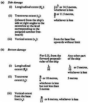
For the purpose of calculating hypothetical oil outflow from oil tankers, three dimensions of the extent of damage of a parallelepiped on the side and bottom of the ship are assumed as follows. In the case of bottom damages two conditions are set forth to be applied individually to the stated portions of the oil tanker.
-
Wherever the symbols given in this Regulation appear in this Chapter, they have the meaning as defined in this Regulation.
Regulation 23
Hypothetical Outflow of Oil
-
The hypothetical outflow of oil in the case of side damage (Oc ) and bottom damage (Os) shall be calculated by the following formulae with respect to compartments breached by damage to all conceivable locations along the length of the ship to the extent as defined in Regulation 22 of this Annex.
-
for side damages:

-
for bottom damages:

where: Wi = volume of a wing tank in cubic metres assumed to be breached by the damage as specified in Regulation 22 of this Annex; Wi for a segregated ballast tank may be taken equal to zero,
Ci = volume of a centre tank in cubic metres assumed to be breached by the damage as specified in Regulation 22 of this Annex; Ci for a segregated ballast tank may be taken equal to zero.
 when bi is equal to or greater than tc, Ki shall be taken equal to zero,
 when hi is equal to or greater than vs, Zi shall be taken equal to zero,
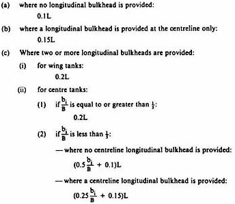
bi = width of wing tank in metres under consideration measured inboard from the ship's side at right angles to the centreline at the level corresponding to the assigned summer freeboard.
hi = minimum depth of the double bottom in metres under consideration; where no double bottom is fitted hi shall be taken equal to zero.
Whenever symbols given in this paragraph appear in this Chapter, they have the meaning as defined in this Regulation.
-
-
If a void space or segregated ballast tank of a length less than lc as defined in Regulation 22 of this Annex is located between wing oil tanks, Oc in formula (I) may be calculated on the basis of volume Wi being the actual volume of one such tank (where they are of equal capacity) or the smaller of the two tanks (if they differ in capacity) adjacent to such space, multiplied by Si as defined below and taking for all other wing tanks involved in such a collision the value of the actual full volume.

where li = length in metres of void space or segregated ballast tank under consideration.
-
Credit shall only be given in respect of double bottom tanks which are either empty or carrying clean water when cargo is carried in the tanks above.
-
Where the double bottom does not extend for the full length and width of the tank involved, the double bottom is considered non-existent and the volume of the tanks above the area of the bottom damage shall be included in formula (II) even if the tank is not considered breached because of the installation of such a partial double bottom.
-
Suction wells may be neglected in the determination of the value hi provided such wells are not excessive in area and extend below the tank for a minimum distance and in no case more than half the height of the double bottom. If the depth of such a well exceeds half the height of the double bottom, hi shall be taken equal to the double bottom height minus the well height.
Piping serving such wells if installed within the double bottom shall be fitted with valves or other closing arrangements located at the point of connexion to the tank served to prevent oil outflow in the event of damage to the piping. Such piping shall be installed as high from the bottom shell as possible. These valves shall be kept closed at sea at any time when the tank contains oil cargo, except that they may be opened only for cargo transfer needed for the purpose of trimming of the ship.
-
In the case where bottom damage simultaneously involves four centre tanks, the value of Os may be calculated according to the formula

-
An administration may credit as reducing oil outflow in case of bottom damage, an installed cargo transfer system having an emergency high suction in each cargo oil tank, capable of transferring from a breached tank or tanks to segregated ballast tanks or to available cargo tankage if it can be assured that such tanks will have sufficient ullage. Credit for such a system would be governed by ability to transfer in two hours of operation oil equal to one half of the largest of the breached tanks involved and by availability of equivalent receiving capacity in ballast or cargo tanks. The credit shall be confined to permitting calculation of Os according to formula (III). The pipes for such suctions shall be installed at least at a height not less than the vertical extent of the bottom damage vs. The Administration shall supply the Organization with the information concerning the arrangements accepted by it, for circulation to other Parties to the Convention.
Regulation 24
Limitation of Size and Arrangement of Cargo Tanks
-
Every new oil tanker shall comply with the provisions of this Regulation. Every existing oil tanker shall be required, within two years after the date of entry into force of the present Convention, to comply with the provisions of this Regulation if such a tanker falls into either of the following categories:
-
a tanker, the delivery of which is after 1 January 1977; or
-
a tanker to which both the following conditions apply:
-
-
delivery is not later than 1 January 1977; and
-
the building contract is placed after 1 January 1974, or in cases where no building contract has previously been placed, the keel is laid or the tanker is at a similar stage of construction after 30 June 1974.
-
Cargo tanks of oil tankers shall be of such size and arrangements that the hypothetical outflow Oc or Os calculated in accordance with the provisions of Regulation 23 of this Annex anywhere in the length of the ship does not exceed 30,000 cubic metres or 400 3√DW, whichever is the greater, but subject to a maximum of 40,000 cubic metres.
-
The volume of any one wing cargo oil tank of an oil tanker shall not exceed seventy-five per cent of the limits of the hypothetical oil outflow referred to in paragraph (2) of this Regulation. The volume of any one centre cargo oil tank shall not exceed 50,000 cubic metres. However, in segregated ballast oil tankers as defined in Regulation 13 of this Annex, the permitted volume of a wing cargo oil tank situated between two segregated ballast tanks, each exceeding lc in length, may be increased to the maximum limit of hypothetical oil outflow provided that the width of the wing tanks exceeds tc.
-
The length of each cargo tank shall not exceed 10 metres or one of the following values, whichever is the greater:
-
In order not to exceed the volume limits established by paragraphs (2), (3) and (4) of this Regulation and irrespective of the accepted type of cargo transfer system installed, when such system interconnects two or more cargo tanks, valves or other similar closing devices shall be provided for separating the tanks from each other. These valves or devices shall be closed when the tanker is at sea.
-
Lines of piping which run through cargo tanks in a position less than tc from the ship's side or less than vc from the ship's bottom shall be fitted with valves or similar closing devices at the point at which they open into any cargo tank. These valves shall be kept closed at sea at any time when the tanks contain cargo oil, except that they may be opened only for cargo transfer needed for the purpose of trimming of the ship.
Regulation 25
Subdivision and Stability
-
Every new oil tanker shall comply with the subdivision and damage stability criteria as specified in paragraph (3) of this Regulation, after the assumed side or bottom damage as specified in paragraph (2) of this Regulation, for any operating draught reflecting actual partial or full load conditions consistent with trim and strength of the ship as well as specific gravities of the cargo. Such damage shall be applied to all conceivable locations along the length of the ship as follows:
-
in tankers of more than 225 metres in length, anywhere in the ship's length;
-
in tankers of more than 150 metres, but not exceeding 225 metres in length, anywhere in the ship's length except involving either after or forward bulkhead bounding the machinery space located aft. The machinery space shall be treated as a single floodable compartment;
-
in tankers not exceeding 150 metres in length, anywhere in the ship's length between adjacent transverse bulkheads with the exception of the machinery space. For tankers of 100 metres or less in length where all requirements of paragraph (3) of this Regulation cannot be fulfilled without materially impairing the operational qualities of the ship, Administrations may allow relaxations from these requirements.
Ballast conditions where the tanker is not carrying oil in cargo tanks excluding any oil residue, shall not be considered.
-
-
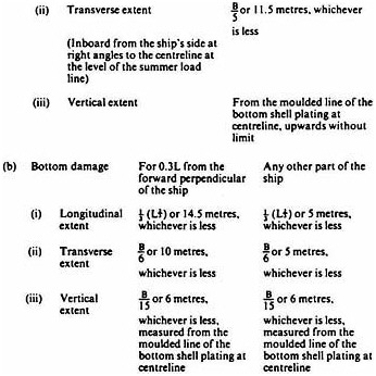
The following provisions regarding the extent and the character of the assumed damage shall apply:
-
If any damage of a lesser extent than the maximum extent of damage specified in sub-paragraphs (a) and (b) of this paragraph would result in a more severe condition, such damage shall be considered.
-
Where the damage involving transverse bulkheads is envisaged as specified in sub-paragraphs (1)(a) and (b) of this Regulation, transverse watertight bulkheads shall be spaced at least at a distance equal to the longitudinal extent of assumed damage specified in sub-paragraph (a) of this paragraph in order to be considered effective. Where transverse bulkheads are spaced at a lesser distance, one or more of these bulkheads within such extent of damage shall be assumed as non-existent for the purpose of determining flooded compartments.
-
Where the damage between adjacent transverse watertight bulkheads is envisaged as specified in sub-paragraph (1)(c) of this Regulation, no main transverse bulkhead or a transverse bulkhead bounding side tanks or double bottom tanks shall be assumed damaged, unless:
-
the spacing of the adjacent bulkheads is less than the longitudinal extent of assumed damage specified in sub-paragraph (a) of this paragraph; or
-
-
there is a step or a recess in a transverse bulkhead of more than 3.05 metres in length, located within the extent of penetration of assumed damage. The step formed by the after peak bulkhead and after peak tank top shall not be regarded as a step for the purpose of this Regulation.
-
If pipes, ducts or tunnels are situated within the assumed extent of damage, arrangements shall be made so that progressive flooding cannot thereby extend to compartments other than those assumed to be floodable for each case of damage.
-
Oil tankers shall be regarded as complying with the damage stability criteria if the following requirements are met:
-
The final waterline, taking into account sinkage, heel and trim, shall be below the lower edge of any opening through which progressive flooding may take place. Such openings shall include air pipes and those which are closed by means of weathertight doors or hatch covers and may exclude those openings closed by means of watertight manhole covers and flush scuttles, small watertight cargo tank hatch covers which maintain the high integrity of the deck, remotely operated watertight sliding doors, and side scuttles of the non-opening type.
-
In the final stage of flooding, the angle of heel due to unsymmetrical flooding shall not exceed 25 degrees, provided that this angle may be increased up to 30 degrees if no deck edge immersion occurs.
-
The stability in the final stage of flooding shall be investigated and may be regarded as sufficient if the righting lever curve has at least a range of 20 degrees beyond the position of equilibrium in association with a maximum residual righting lever of at least 0.1 metre within the 20 degrees range; the area under the curve within this range shall not be less than 0.0175 metre radians. Unprotected openings shall not be immersed within this range unless the space concerned is assumed to be flooded. Within this range, the immersion of any of the openings listed in sub-paragraph (a) of this paragraph and other openings capable of being closed weathertight may be permitted.
-
The Administration shall be satisfied that the stability is sufficient during intermediate stages of flooding.
-
Equalization arrangements requiring mechanical aids such as valves or cross-levelling pipes, if fitted, shall not be considered for the purpose of reducing an angle of heel or attaining the minimum range of residual stability to meet the requirements of sub-paragraphs (a), (b) and (c) of this paragraph and sufficient residual stability shall be maintained during all stages where equalization is used. Spaces which are linked by ducts of a large cross-sectional area may be considered to be common.
-
-
The requirements of paragraph (1) of this Regulation shall be confirmed by calculations which take into consideration the design characteristics of the ship, the arrangements, configuration and contents of the damaged compartments; and the distribution, specific gravities and the free surface effect of liquids. The calculations shall be based on the following:
-
Account shall be taken of any empty or partially filled tank, the specific gravity of cargoes carried, as well as any outflow of liquids from damaged compartments.
-
The permeabilities assumed for spaces flooded as a result of damage shall be as follows:
-
|
Spaces |
Permeabilities |
|
Appropriated to stores |
0.60 |
|
Occupied by accommodation |
0.95 |
|
Occupied by machinery |
0.85 |
|
Voids |
0.95 |
|
Intended for consumable liquids |
0 to 0.95* |
|
Intended for other liquids |
0 to 0.95* |
-
The buoyancy of any superstructure directly above the side damage shall be disregarded. The unflooded parts of superstructures beyond the extent of damage, however, may be taken into consideration provided that they are separated from the damaged space by watertight bulkheads and the requirements of sub-paragraph (3)(a) of this Regulation in respect of these intact spaces are complied with. Hinged watertight doors may be acceptable in watertight bulkheads in the superstructure.
-
The free surface effect shall be calculated at an angle of heel of 5 degrees for each individual compartment. The Administration may require or allow the free surface corrections to be calculated at an angle of heel greater than 5 degrees for partially filled tanks.
-
In calculating the effect of free surfaces of consumable liquids it shall be assumed that, for each type of liquid at least one transverse pair or a single centreline tank has a free surface and the tank or combination of tanks to be taken into account shall be those where the effect of free surfaces is the greatest.
-
The Master of every new oil tanker and the person in charge of a new non-self-propelled oil tanker to which this Annex applies shall be supplied in an approved form with:
-
information relative to loading and distribution of cargo necessary to ensure compliance with the provisions of this Regulation; and
-
data on the ability of the ship to comply with damage stability criteria as determined by this Regulation, including the effect of relaxations that may have been allowed under sub-paragraph (1)(c) of this Regulation.
-


