National Academies Press: OpenBook

Tanker Spills: Prevention by Design (1991)

Chapter: Appendix E: Double Hull Tanker Design

« Previous: Appendix D: 35,000 DWT Tanker Cargo Capacity and Damage Stability Study
Suggested Citation:"Appendix E: Double Hull Tanker Design." National Research Council. 1991. Tanker Spills: Prevention by Design. Washington, DC: The National Academies Press. doi: 10.17226/1621.
×

APPENDIX E
Double Hull Tanker Design*

DOUBLE BOTTOM HEIGHT REQUIREMENTS

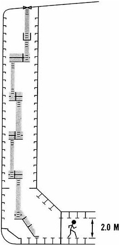
The existing IMO requirements are 1/15th the beam of the ship or two meters, whichever is less. We believe a better criteria would be 1/15th the beam of the ship but in no case less than two meters nor be required to be greater than three meters. Two meters is adequate for smaller vessels; but as the vessel size is increased and structural stiffeners increase in size, personnel access and air circulation become problems if the height of the double bottom is simply limited to two meters. There are many ways to design a double bottom, but in larger size vessels either longitudinals encroach into the available space to make access very difficult or longitudinal girders and transverse frames produce compartments that have the same or worse effect. On the other hand, we believe that three meters is sufficient height, even in the largest size vessels (VLCC's). If the height of the double bottom is increased beyond that, the vessel's stability is further impaired—the greater the double bottom height, the harder it is to design a vessel that has good damage stability characteristics. Furthermore, maintenance of the double bottom overhead becomes more difficult due to accessibility if the height is increased much beyond three meters. To illustrate the situation, compare the access of a "2M" double hull design currently being built in the Far East (Figure E-1) to that of a current Chevron design, Figure E-2. Note that reasonable access is closely linked to structural design, not simply the height/width of void spaces.

*  

Chevron Shipping Company (adapted), October 1990.

Suggested Citation:"Appendix E: Double Hull Tanker Design." National Research Council. 1991. Tanker Spills: Prevention by Design. Washington, DC: The National Academies Press. doi: 10.17226/1621.
×

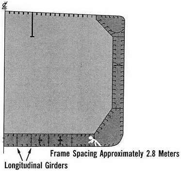
FIGURE E-1 Vessel currently being built in the Far East: ballast tank (midships) 2 meters wide.

DOUBLE SIDE TANK WIDTH REQUIREMENTS

Double side tanks require a minimum width of two meters. We believe the criteria should be 1/15th the beam but in no case less than two meters nor be required to be greater than three meters. No reasonable double side tank will be able to prevent a high impact collision from penetrating through the side tank. The width criteria should be established based on a width sufficient to prevent damage to the inner side in a glancing-type contact.

In addition to damage prevention to the inner side, access and maintenance issues must be addressed. This is somewhat less of a problem in the side tanks than in the double bottom tanks because there is less structure in the upper portions of these tanks; but in the bottom part, the problem is the same.

Suggested Citation:"Appendix E: Double Hull Tanker Design." National Research Council. 1991. Tanker Spills: Prevention by Design. Washington, DC: The National Academies Press. doi: 10.17226/1621.
×

FIGURE E-2 Chevron 130,000 DWT ballast tank (midships).

Suggested Citation:"Appendix E: Double Hull Tanker Design." National Research Council. 1991. Tanker Spills: Prevention by Design. Washington, DC: The National Academies Press. doi: 10.17226/1621.
×

MAINTENANCE AND SAFETY

The double hull tanker will require frequent inspection of the double hull spaces to ensure that coating failures and corrosion are detected and dealt with on a timely basis. Therefore, access for maintenance must be sufficient to allow for easy inspection of the spaces and must allow for the effective removal of injured personnel. Openings in the structure at least one meter × 0.6 meter should be provided in every compartment for personnel movement in both the fore and aft and the athwartships directions. Provision for adequate air circulation in all double hull tanks is essential and purge pipes may be required in some locations. Figure E-3 shows the purge pipe arrangement that we made in order to get air circulation through the ballast tanks that have a dead leg at the centerline bulkhead. For entrance of men, it will be necessary to know that there is a satisfactory atmosphere throughout the tank. The more subdivided the tank is, the more difficult this becomes. We believe that a purge line is essential to get proper air circulation in the tank.

COATINGS

The massive amount of ballast tank surface area that is present in a double hull tanker makes corrosion protection a vital issue. These tanks should be coated and protected with cathodic protection methods to provide protection backup when coating failures occur. Failure to do so will result in corrosion and eventual leakage of cargo into the double bottom space with the resulting buildup of explosive vapors. Application of high quality coatings, with cathodic protection systems to give good corrosion protection in the ballast tank spaces will be critical to long-term operation without problems.

DAMAGE STABILITY CRITERIA

The current IMO requirements for damage stability which, in the case of most large tankers, means damage to two tanks. Our experience in grounding incidents is that the longitudinal extent of damage is frequently greater than is provided for under current criteria. We believe a double hull tanker should be able to survive damage which extends the full longitudinal extent of the cargo area of the vessel if the damage does not penetrate the vessel's inner bottom. For a double hull ship, intact stability is reduced by a combination of the higher center of gravity of the cargo and the possible large free surface in the center cargo tanks if a center line bulkhead is not fitted. If a double-bottom centerline bulkhead is fitted and asymmetric flooding can occur when the outer hull is breached, the combination of reduced

Suggested Citation:"Appendix E: Double Hull Tanker Design." National Research Council. 1991. Tanker Spills: Prevention by Design. Washington, DC: The National Academies Press. doi: 10.17226/1621.
×

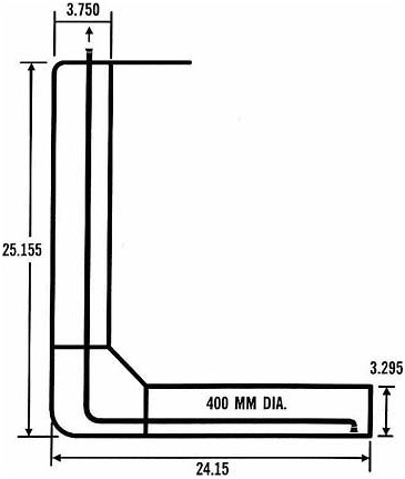
FIGURE E-3 Double bottom ''L" tank purging arrangement.

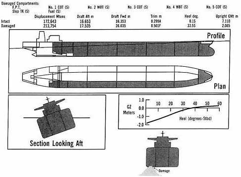
initial stability and the creation of large heeling moments can cause the vessel to capsize when damage extends over less than half the vessel's length. We should strive to require a standard of damage stability that provides for the vessel's survivability at least equal to the survivability of a typical single hull vessel. Figure E-4 shows the free-floating condition of a single hull after being damaged nearly its full length (damaged area shaded). As can be seen, the vessel is heeled to 33.5 degrees but remains afloat.

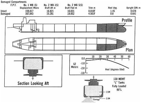
In Figure E-5, we depict an industry standard 130,000 DWT vessel with 2.0 meter double hull and "L" shaped ballast tanks. If it is loaded 98% full

Suggested Citation:"Appendix E: Double Hull Tanker Design." National Research Council. 1991. Tanker Spills: Prevention by Design. Washington, DC: The National Academies Press. doi: 10.17226/1621.
×

FIGURE E-4 Free-floating damaged condition.

Suggested Citation:"Appendix E: Double Hull Tanker Design." National Research Council. 1991. Tanker Spills: Prevention by Design. Washington, DC: The National Academies Press. doi: 10.17226/1621.
×

FIGURE E-5 Industrial standard 130,000 DWT free-floating damaged condition—98% full.

Suggested Citation:"Appendix E: Double Hull Tanker Design." National Research Council. 1991. Tanker Spills: Prevention by Design. Washington, DC: The National Academies Press. doi: 10.17226/1621.
×

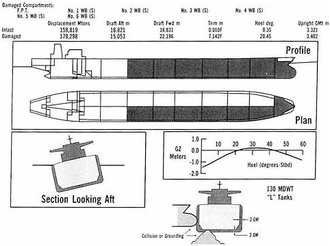
and damaged to the extent indicated in the figures by the shaded areas, it will survive. If it is damaged further (into No. 7 cargo tank), it will capsize. If the same vessel is loaded with a heavier cargo so that, although fully loaded, the cargo tanks are only 96% full, then the vessel capsizes with far less damage (see Figure E-6). While it is prudent good marine practice to fill tanks to 98%, whether it is done in actual practice, is a question.
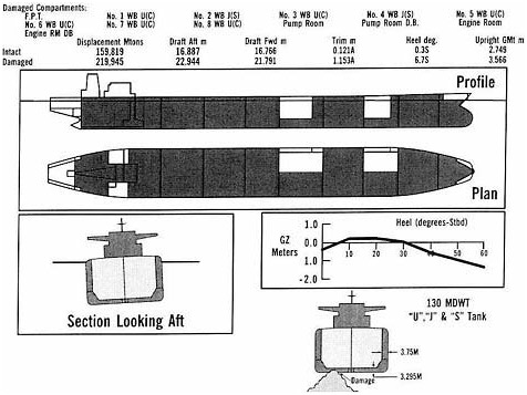
THE CHEVRON DESIGN

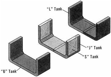
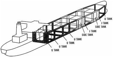
The Chevron 130,000 DWT vessels have double-hull dimensions that meet B-15 criteria and an arrangement of double-hull that allow it to survive substantial bottom damage. It uses a combination of "U", "J", and "S" tanks, as described in Figures E-7 and E-8. It also has access and maintenance arrangements that allow relatively easy inspection and maintenance. We believe, with this design, we've mitigated some of the problems inherent in double-hull designs. The tank arrangement and damage stability characteristics of the Chevron vessel is shown in Figure E-9. The Chevron vessel utilizes many "U'' ballast tanks to minimize the capsizing moments that are created by "L" tanks. The "U" tanks are fine, if full or empty, but create problems during loading and discharge of the vessel if too many are partially full simultaneously. Two sets of "J" tanks were arranged to provide for heel control while working cargo. The "S" tanks were included to provide buoyancy in a damaged condition, as the "U" tanks will flood across the vessel and not cause heeling, but sinkage will be greater. To minimize the free surface effects which could be created inadvertently by flooding too many "U" tanks simultaneously, three center cargo tanks have centerline subdivision bulkheads.

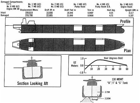
This arrangement has very good damage stability characteristics as shown in Figure E-9. The vessel can be damaged from the bow through to the engine room and remain stable and afloat. The computer-generated sketch of the vessel in this figure doesn't show the starboard side "S" tanks to be undamaged, but that is the case. If loaded to 96%, the stability is reduced, but the vessel survives this condition, as well, as shown in Figure E-10.

Suggested Citation:"Appendix E: Double Hull Tanker Design." National Research Council. 1991. Tanker Spills: Prevention by Design. Washington, DC: The National Academies Press. doi: 10.17226/1621.
×

FIGURE E-6 Free-floating damaged condition.

Suggested Citation:"Appendix E: Double Hull Tanker Design." National Research Council. 1991. Tanker Spills: Prevention by Design. Washington, DC: The National Academies Press. doi: 10.17226/1621.
×

FIGURE E-7 Double-hull tank configurations.

FIGURE E-8 Chevron 130,000 DWT double hull tank arrangement.

Suggested Citation:"Appendix E: Double Hull Tanker Design." National Research Council. 1991. Tanker Spills: Prevention by Design. Washington, DC: The National Academies Press. doi: 10.17226/1621.
×

FIGURE E-9 Chevron 130,000 DWT double hull free-floating damaged condition—98% full.

Suggested Citation:"Appendix E: Double Hull Tanker Design." National Research Council. 1991. Tanker Spills: Prevention by Design. Washington, DC: The National Academies Press. doi: 10.17226/1621.
×

FIGURE E-10 Chevron 130,000 DWT double hull free-floating damaged condition—96% full.

Suggested Citation:"Appendix E: Double Hull Tanker Design." National Research Council. 1991. Tanker Spills: Prevention by Design. Washington, DC: The National Academies Press. doi: 10.17226/1621.
×
Page 226
Suggested Citation:"Appendix E: Double Hull Tanker Design." National Research Council. 1991. Tanker Spills: Prevention by Design. Washington, DC: The National Academies Press. doi: 10.17226/1621.
×
Page 227
Suggested Citation:"Appendix E: Double Hull Tanker Design." National Research Council. 1991. Tanker Spills: Prevention by Design. Washington, DC: The National Academies Press. doi: 10.17226/1621.
×
Page 228
Suggested Citation:"Appendix E: Double Hull Tanker Design." National Research Council. 1991. Tanker Spills: Prevention by Design. Washington, DC: The National Academies Press. doi: 10.17226/1621.
×
Page 229
Suggested Citation:"Appendix E: Double Hull Tanker Design." National Research Council. 1991. Tanker Spills: Prevention by Design. Washington, DC: The National Academies Press. doi: 10.17226/1621.
×
Page 230
Suggested Citation:"Appendix E: Double Hull Tanker Design." National Research Council. 1991. Tanker Spills: Prevention by Design. Washington, DC: The National Academies Press. doi: 10.17226/1621.
×
Page 231
Suggested Citation:"Appendix E: Double Hull Tanker Design." National Research Council. 1991. Tanker Spills: Prevention by Design. Washington, DC: The National Academies Press. doi: 10.17226/1621.
×
Page 232
Suggested Citation:"Appendix E: Double Hull Tanker Design." National Research Council. 1991. Tanker Spills: Prevention by Design. Washington, DC: The National Academies Press. doi: 10.17226/1621.
×
Page 233
Suggested Citation:"Appendix E: Double Hull Tanker Design." National Research Council. 1991. Tanker Spills: Prevention by Design. Washington, DC: The National Academies Press. doi: 10.17226/1621.
×
Page 234
Suggested Citation:"Appendix E: Double Hull Tanker Design." National Research Council. 1991. Tanker Spills: Prevention by Design. Washington, DC: The National Academies Press. doi: 10.17226/1621.
×
Page 235
Suggested Citation:"Appendix E: Double Hull Tanker Design." National Research Council. 1991. Tanker Spills: Prevention by Design. Washington, DC: The National Academies Press. doi: 10.17226/1621.
×
Page 236
Suggested Citation:"Appendix E: Double Hull Tanker Design." National Research Council. 1991. Tanker Spills: Prevention by Design. Washington, DC: The National Academies Press. doi: 10.17226/1621.
×
Page 237
Next: Appendix F: Comparative Study on Potential Oil Spill in Collision and/or Grounding--Different Tanker Designs »
Tanker Spills: Prevention by Design Get This Book
×
 Tanker Spills: Prevention by Design
Buy Hardback | $39.95
MyNAP members save 10% online.
Login or Register to save!
Download Free PDF

Can we design an oil tanker that meets our complex demands for environmental protection, economical operation, and crew safety? This volume evaluates and ranks a wide variety of tank ship hull designs proposed by experts around the world.

Based on extensive research and studies, the book explores the implications of our rising demand for petroleum and increase in tanker operations; U.S. government regulations and U.S. Coast Guard policies regarding designs for new tank vessel construction; how new ship design would affect crew safety, maintenance, inspection, and other technical issues; the prospects for retrofitting existing tankers to reduce the risk of oil spills; and more.

The conclusions and recommendations will be particularly important to maritime safety regulators in the United States and abroad; naval architects; ship operators and engineers; and officials in the petroleum, shipping, and marine insurance industries.

READ FREE ONLINE

  1. ×

    Welcome to OpenBook!

    You're looking at OpenBook, NAP.edu's online reading room since 1999. Based on feedback from you, our users, we've made some improvements that make it easier than ever to read thousands of publications on our website.

    Do you want to take a quick tour of the OpenBook's features?

    No Thanks Take a Tour »
  2. ×

    Show this book's table of contents, where you can jump to any chapter by name.

    « Back Next »
  3. ×

    ...or use these buttons to go back to the previous chapter or skip to the next one.

    « Back Next »
  4. ×

    Jump up to the previous page or down to the next one. Also, you can type in a page number and press Enter to go directly to that page in the book.

    « Back Next »
  5. ×

    Switch between the Original Pages, where you can read the report as it appeared in print, and Text Pages for the web version, where you can highlight and search the text.

    « Back Next »
  6. ×

    To search the entire text of this book, type in your search term here and press Enter.

    « Back Next »
  7. ×

    Share a link to this book page on your preferred social network or via email.

    « Back Next »
  8. ×

    View our suggested citation for this chapter.

    « Back Next »
  9. ×

    Ready to take your reading offline? Click here to buy this book in print or download it as a free PDF, if available.

    « Back Next »
Stay Connected!