
APPENDIX F
Comparative Study on Potential Oil Spill in Collision and/or Grounding— Different Tanker Designs
DET NORSKE VERITAS
The appendixes to this study are not included. Committee comments on assumptions and conclusions can be found at the end of the Det norske Veritas report on page 299 and following.
PREAMBLE
The recent casualties of larger oil tankers resulting in severe oil spills, together with oil spills from a number of smaller tankers grounded, have caused growing concern in many countries.
A review of the casualties indicates that human and operational aspects have been decisive factors in most casualties. In view of the serious consequences of every single oil spill, however, improvements in existing measures related to ship design and equipment will also have to be considered with the objective of reducing the potential for oil spills.
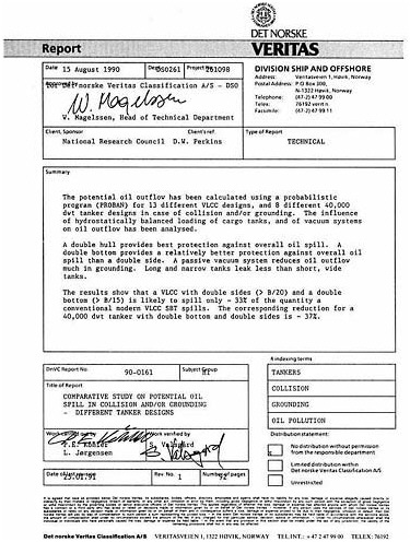
In this report an assessment of the potential oil outflow from VLCCs and 40,000 dwt tankers in case of collision and grounding is presented. The objective of the study has been to investigate how double sides, double bottom, tank size and tank location influence the amount of oil escaping from a damaged VLCC.
The study is based on available statistical information on damage location and extent. A novel probabilistic approach has been adopted to account for uncertainties in damage location and extent.
Additional oil spill caused by a grounded tanker possibly breaking in parts has not been considered in this study as this would necessitate a rather detailed analysis on the ultimate strength margins in damaged condition. Possible additional oil spill when salvaging a grounded tanker has not been considered in the study.
Neither has structural damage caused by explosion and fire resulting in oil spill been considered.
The results presented in this report are applicable to tankers in general.
The VLCC study is an extension of a joint Scandinavian study carried out earlier in 1990/8/. At the request of the National Research Council, two additional VLCCs - the intermediate oil tight deck and the hydrostatically balance loaded VLCC respectively, have been analysed and the results included in the graphs together with the other VLCCs. The 40,000 dwt tanker study was carried out exclusively for National Research Council.
Det norske Veritas Classification A/S and the participants of the first VLCC study accept no liability for any loss, damage or expense allegedly caused directly or indirectly, when using or referring to the results presented in this report.
List Of Contents
|
|
||||
|
|
||||
|
|
||||
|
|
||||
|
|
||||
|
|
||||
|
|
||||
|
|
||||
|
|
||||
|
|
||||
|
|
||||
|
|
||||
|
|
||||
|
|
||||
|
|
||||
|
|
||||
|
|
||||
|
|
||||
|
|
||||
|
|
||||
|
|
||||
|
|
||||
|
|
||||
|
|
||||
|
|
||||
|
|
||||
|
|
||||
|
|
||||
|
5.1 Comparison of Performance for VLCCs vs 40,000 dwt Tankers |
|
|||
|
|
||||
|
|
||||
|
|
||||
|
APPENDIX 1: A Short Description of PROBAN |
|
|||
|
APPENDIX 2: PROBAN Limit State Functions for Design 1A |
|
|||
|
APPENDIX 3: Trim, Stability, Bending Moments and Shear Forces. Weight Estimation for VLCC |
|
1.
Scope Of Work
The objective of this study is to shed some light on the merits of building tankers with double sides and/or double bottom in order to reduce the probability of oil outflow in case of collision and/or grounding.
The analysis is focused on the cargo area only; - no crude oil is assumed to be located forward of the collision bulkhead, nor aft of the forward engine room bulkhead. Possible fuel oil leakage has not been considered in the study; - the fuel oil tanks are located aft of the forward engine room bulkhead. As the fuel tank location is assumed similar in all designs studied, pollution potential from fuel tanks is equal and hence not included in the study.
In this study the potential oil outflow from 11 different VLCC designs with double sides and/or double bottom have been compared with the potential oil outflow from a modern conventional VLCC of 280,000 dwt having segregated ballast tanks. In addition, the potential oil outflow from a modern conventional VLCC SBT with hydrostatically balanced loading of cargo tanks has been evaluated.
All VLCC designs have the same main particulars and body plan as the modern conventional VLCC. The length of the cargo area is equal for all VLCCs; the total cargo and ballast capacity respectively is approximately equal to that of the VLCC SBT within the cargo area for all VLCCs analysed.
Eight 40,000 dwt designs have been analysed. All designs have the same main particulars and body plan. The length of the cargo area is equal for all designs; - the ballast capacity within the cargo area varies from approximately 14,000 to 17,5000 tons depending on arrangement.
The oil outflow in collision and grounding has been estimated using available statistical information on damage extent, combined with basic laws of mechanics and PROBAN1 , a probabilistic analysis program developed by Veritas Research/1/.
The calculated potential oil outflow in collision and grounding has been combined using general casualty frequency statistics to provide an overall ranking of the different designs.
The influence of vacuum systems on the oil outflow in grounding has been investigated for VLCCs by amending the theory and formulae developed in connection with the DNVC - Pollution Prevention Class Notation work into the PROBAN oil outflow model.
The results from the VLCC and 40,000 dwt tanker studies have been discussed and extrapolated for 80,000 dwt tankers.
2.
Estimation Of Oil Outflow In Collision And Grounding
The potential oil outflow is estimated separately for collision and grounding casualties, and combined using a weighing based on collision and grounding casualty frequencies for tankers.
2.1 Oil Outflow in Collision
2.1.1 Basic Assumptions
Several simplifying assumptions have been made w.r.t. the collision process. In order to avoid optimistic results the assumptions made are conservative.
It is assumed that oil begins to escape from a cargo tank when the bow of the striking ship touches and penetrates one of the sides or corners of the tank. No large deformations resulting in yielding of tank sides have been assumed. Hence, at contact the tank is penetrated.
In the analysis it is postulated that the bow is wedge shaped and remains wedge shaped after having penetrated the hull plating. As the vertical bow penetrates the tank, the whole tank is ruptured from bottom to top. This assumption has been made in order to conform with the MARPOL/2/ assumption that all oil will escape from a damaged tank over time.
A consequence of these assumptions is that the results presented for collision strictly apply for the final condition only i.e. when all oil has escaped from a holed tank. For more accurate estimates on oil outflow during the collision a detailed modeling of bow crushing behaviour and ship side structural response during the collision process, including the changes in ship speeds and headings, and added mass effects, would be necessary/4,5/. This has been beyond the scope for this study.
It should be stressed that only damage in way of the collision contact point has been considered. Damages far away from the contact point, such as possible tearing in weld seems due to excessive tension potentially resulting in oil leakage, have not been considered.
As for possible explosions due to friction heat and sparks generated in a collision, it is assumed that the inert gas system is effective; - should the system fail then structural damage may become extensive. These aspects have not been considered in the study.
SEE COMMITTEE INTERPRETATIONS OF DNV COLLISION ASSUMPTIONS ON PAGE 299.
2.1.2 Damage Analysis Procedure
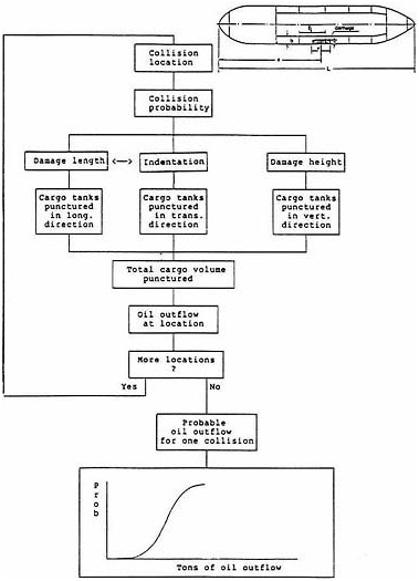
The procedure for calculating the potential oil outflow in collision is shown in the flow chart below (Fig.2.1).
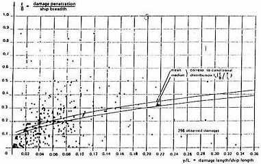
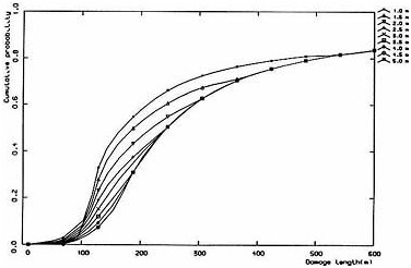
The interdependence between collision damage length and damage penetration used in this study is shown in Fig.2.2. No information is given on ship speeds and sizes, nor on the number of tankers included in the basic population of 296 ships.
The damage length and damage penetration values in Fig.2.2 include implicitly elastic and plastic deformation of the bow and side structure, the speeds of both ships, changes in ship motions and accelerations as well as any mass effects.
A multilognormal distribution for damage penetration and length has been calculated based on Fig.2.2. The distribution has been used in the PROBAN analysis for defining the extent of structural damage.
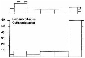
The distribution of collision points along the ship hull is shown in Fig.2.3 for 332 collisions. The distribution includes struck and striking ships. This explains the large percentage of collisions in the bow region. Considering only struck ships, the distribution becomes bell shaped with about 30% of collisions aft and in the bow. No information on ship types or sizes is given; - it is assumed that the distribution is valid also for tankers.
Fig.2.2 includes damages to struck ships as well as striking ships. No information is given on the number of damages to struck and striking ships respectively. Referring to the collision point distribution in Fig.2.3, damages to the relatively more rigid bow region are emphasized in Fig.2.2. The multilognormal distribution calculated may thus be somewhat optimistic for side damages i.e. the damage lengths and penetrations might be short.
The effect of a double side structure on damage penetration has been considered by introducing an equivalent penetration depth. This equivalent penetration depth is obtained as a function of the single side penetration depth, the stiffness of the inner side structure in relation to the outer side structure and the distance between the outer and inner sides. For simplicity, elastic deformation only is assumed. In the analysis it has been assumed that the inner side has a mean stiffness of 0.7 of the outer side with a standard deviation of 0.1.
The ship length has been divided into 50 sections of equal length. Using the damage extent distribution, the cargo volume punctured i.e. number and size of tanks, and the resulting oil outflow, has been calculated for the 51 locations (ends of each section) along the ship hull.
The collision point distribution has been used for weighing the oil outflow calculated at the 51 locations. The oil outflow is obtained as volume (m3), and may be converted to tons using the specific gravity of oil.
In Appendix 2 the limit state functions used for calculation of oil outflow in collision and grounding are given for design 1A as illustration.
2.2 Oil Outflow in Grounding
2.2.1 Basic assumptions
The simplifying assumptions made in the grounding analysis relate to the damage extent and oil outflow. Again, the assumptions made are considered to be conservative.
It is assumed that the ship has forward speed in grounding, i.e. the damage starts in the bow of the ship and develops towards the stern.
Damage caused by grounding while the ship is adrift, when the ship is turning or going astern, has not been considered.
The ground is assumed to be a solid rock which does not crush during the grounding process. The rock is assumed to be wedge shaped (i.e. triangular in the transverse yz-plane) having a constant breadth. A sensitivity analysis has been performed regarding the influence of the rock shape on damage extent (see below). Grounding on sand banks or mud bottom has not been considered as the damage in this case primarily would be local indentations, possibly combined with tearing of welds.
As the rock comes into contact with one of the sides of a tank, the bottom or a corner of a tank, the hull plating is assumed to be penetrated. Oil begins to escape until hydrostatic equilibrium is achieved in the damaged tank. Should the ship side be damaged in grounding, then it is assumed that all oil which is below the intact side plating, will escape from the tank and be substituted with water. In addition, due to the reduced hydrostatic pressure, the oil level will drop in the tank proportionally to the specific gravities of water and oil, and height of side damage.
In the analysis statistical information on maximum vertical extent of damage has been used for the whole damage length. This conservative assumption has been made due to lack of detailed information on the vertical damage extent, or penetration, as a function of damage length. Consequently, the damage lengths calculated may be too short as too much energy is absorbed vertically (see discussion below).
Possible tearing of welds well away from the damage location causing leakage of oil have not been considered (ref. similar assumption in the collision analysis above).
The influence of ship motions during the grounding process have not been considered in detail. During a grounding the ship may develop a forward trim due to shallow water i.e. downward suction of the bow, or due to sudden loss of buoyancy as the forward bottom plating is peeled off. The ship may also run up on the rock lifting the bow. In the analysis a variation in ship draught with ± 0.5 m has been included partly to cover these aspects.
Tidal water effects on oil outflow have not been considered in this study. At low tide more oil may escape from a ship sitting on the rock because of reduced draught. Tidal water may also result in excessive hogging moments when the ship sits on the rock. These moments might result the hull breaking in parts with uncontrolled pollution as an outcome; - this problem may be studied separately in detail using available programs for ultimate strength analysis of the hull girder.
SEE COMMITTEE INTERPRETATIONS OF GROUNDING ASSUMPTIONS ON PAGE 299.
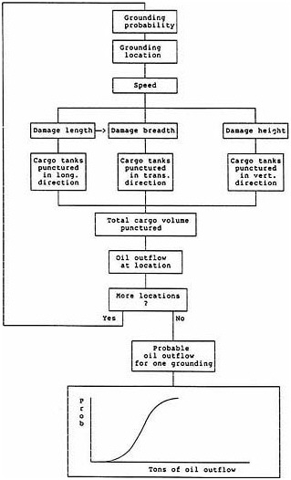
2.2.2 Damage Analysis Procedure
The flow chart for the grounding damage analysis procedure is shown in Fig.2.4.
In analysing the extent of grounding damage, the energy absorbed by the bottom structure being crushed is estimated by following expression/6/:
where
Vs is the volume of material displaced
As is the total area of fracture or tearing
The kinetic energy to be absorbed by the bottom structure in grounding may be expressed as
where m = ms (1+as)
ms = mass of the laden ship
as = added mass coefficient for surge
v = ship's speed at grounding
Assuming all kinetic is transformed into deformation energy, the extent of grounding damage may be expressed for a single bottom ship as follows:
or
where Ld is length of damage in longitudinal direction
tp e is equivalent thickness of bottom plating
tp a is actual thickness of bottom plating
Bd is the breadth of damage
For a ship with a double bottom the corresponding expression is given by
where Bd 1 is breadth of damage to the outer bottom
Bd 2 is breadth of damage to the inner bottom
tp e 1 is equivalent thickness of the outer bottom
tp e 2 is equivalent thickness of the inner bottom
tp a 1 is actual thickness of outer bottom
tp a 2 is actual thickness of inner bottom
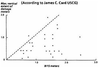
The damage height has been estimated from Fig.2.5 which gives the vertical extent of damage plotted against B/15. From this figure the mean 0.60512 has been calculated with a standard deviation of 0.3807. Most ships included in Fig.2.5 are ships with a deadweight less than 40,000 tons, only 4 being above. The damage height for the largest ship was less than one metre.
In order to study the effects of draught variation on grounding damage extent, the initial draught has been used with a standard deviation of 0.5 m. The draught deviation adopted partly covers variations in the specific gravities of crude oils carried.
The damage breadth has been assumed to be 2.5 times the damage height (IMO/MARPOL/2/ assumption).
In a recent report/7/ Prof. T. Wierzbicki of MIT has studied damage penetration vs. damage breadth, and the validity of the Vaughan formula. The conclusion was that the formula is valid for a breadth-penetration ratio of 6.7, and hence the MARPOL assumption above may result in too long damage lengths (by a factor of 1.8). On the other hand, the use of maximum vertical damage penetration for the whole damage length in the present study results in shorter damages and thus the effect of the above MARPOL breadth assumption on damage length is balanced to some extent.
The number of grounding points in transverse direction has been taken as 7. In case of the grounding point being on the port or starboard side, the damage will extend further in the longitudinal direction as the damage breadth will be reduced (see Eq. 2.3 and 2.4). When calculating the damage length at port and starboard sides, it is assumed that the side structure also will be damaged.
Available information on 24 tanker groundings shows that in 21 cases the damage began in the bow, and in 3 cases in the midship. Out of the damages in the bow, 8 extended to the midship and 3 to the stern. All damages beginning midships extended to stern. The tankers analysed were > 20,000 tdw.
The potential oil outflow in grounding is calculated at 51 locations along the ship hull (as in the collision analysis). The obtained oil outflow is weighed with the probability for damage at that specific location.
3. PROBABILISTIC RANKING OF VLCC DESIGNS
3.1 VLCC Designs Analysed
The VLCC designs considered in this study are all designs that have surfaced recently with the prime objective of reducing the oil outflow in case of a severe casualty.
Common for these designs is that they are hybrids of modern conventional VLCCs with segregated ballast tanks. The oil outflow is expected to be reduced by introducing either double side or double bottom or both, and possibly in addition, utilizing the vacuum method for reducing oil outflow in grounding.
The influence of an intermediate oil tight deck on the potential oil spill has also been studied. The effect of hydrostatically balanced loading of cargo tanks on potential oil outflow from original VLCC SBT has been analysed.
3.1.1 General Features
All VLCC designs analysed have following main particulars:

For all designs, following data has been kept approximately equal:
|
- Total ballast capacity |
≃ 107,000 m3 |
|
- Ballast capacity in cargo area |
≃ 93,000 m3 |
|
- Cargo capacity in cargo area |
≃ 330,000 m3 |
|
- Slop tank after |
|
In addition, all designs have following draught and trim values:
|
- IMO minimum ballast draught |
= 8.3 m |
|
- Design ballast draught |
= 9.95 m |
|
- Trim |
≃ -1.7 … -2.0 m |
MARPOL/2/ requirements to tank lengths have been considered as have requirements to
|
- Hypothetic Outflow |
max. |
30,000 m3 |
|
- Max center-tank |
|
50,000 m3 |
|
- Max Wingtank |
|
22,500 m3 |
3.1.2 Particulars of the VLCC Designs
The numbers below refer to arrangement numbers in Fig.3.1- 3.13, and to numbers in graphs showing the estimated oil outflow for each design. For easy reference, a fold out page showing the VLCC designs compared in this study has been enclosed at the end of this report.
In Fig.3.1-3.13 the box in the low right hand corner shows the IMO/MARPOL/2/ requirements to protective area, the DnVC requirements for Environmental Class Notation PP1 and PP2 respectively, and the corresponding actual values.
Approximate tank volumes are given in Table 3.1 for each design.
-
Modern Conventional VLCC with segregated ballast tanks
This design is used for comparison in order to obtain an indication of how well the other designs perform in case of collision and grounding.
The modern conventional VLCC SBT barely meets the IMO requirements, and falls much short in meeting the DnVC PP1 and PP2 requirements.
The length over depth ratio for the modern conventional VLCC is 10.0-10.5 against 11.5-12.5 for older VLCCs. The increased freeboard of the modern conventional VLCC may result in more oil outflow in case of grounding as compared with an older VLCC.
-
Double side and double bottom
- 1A.
- 1B.
The long tanks in 1A have to be furnished with wash bulkheads in order to reduce sloshing loads. In 1B the tanks are approximately half the length of tanks in 1A.
This design exceeds the IMO, DnVC PP1 and PP2 requirements by a large margin.
-
Double bottom in whole cargo area
Assuming all ballast in the cargo area is carried in the double bottom only, a double bottom of appr. 6.6 m height is required.
This design exceeds the IMO and DnVC PP1 requirements, but is short of the DnVC PP2 requirement.
-
Double side in whole cargo area, single bottom
- 3A.
- 3B.
Design 3A has not been analysed further as a centreline bulkhead is required due to MARPOL requirements; - hence 3A approaches 3B.
3B exceeds the IMO and DnVC PP1 requirements, but falls short of meeting the DnVC PP2 requirement.
-
Double bottom with ballast in side tanks
- 4.
- 4A.
- 4B.
For designs 4 and 4A the double bottom height and the width of side tanks are equal, and all tanks have the same corresponding length.
Design 4B has a lower double bottom height and narrower side tanks than 4 and 4A.
All three alternative designs exceed the IMO as well as the DnVC PP1 and PP2 requirements respectively.
-
Double side in whole cargo area and partial double bottom
In this design the double bottom extends over tanks 1 and 2 only, centre tanks 3-11 have single bottom. There is a centreline bulkhead in tanks 1 and 2.
Please observe the rather low double bottom height and that the side tanks are narrower than in 3B.
IMO and DnVC PP2 requirements are exceeded.
-
Double bottom in side tanks, single bottom in centre tank
This design carries no ballast in centre tanks as opposed to designs 2 and 4. To compensate, there are 5 short ballast side tanks.
The IMO and DnVC PP1 requirements are met, but not DnVC PP2.
-
Tank size half of MARPOL requirements
The number of tanks is significantly higher in this design than for designs above. The ballast is carried in side tanks only, every second side tank carries crude oil. The width of
-
centre tank and side tanks is the same as for the modern conventional VLCC.
Please note that the ballast capacity in cargo area is slightly less than for other designs (∼ 102, 700 m3), and the cargo capacity of ∼ 320, 700 m3 is also lower than the cargo capacity for the other designs above.
This design meets the IMO requirements but not the DnVC requirements for PP1 and PP2.
-
Intermediate Oil Tight Deck
An intermediate deck is fitted 18.5 m above the baseline. All ballast is carried in the side tanks above the intermediate deck. The ballast tanks extend over the whole cargo area.
This design does not meet with the MARPOL requirements for protective tank location, nor DnVC PP requirements.
-
Hydrostatically Balanced Loading
The draught for the original VLCC is increased from 20.8 m to 24.4 m (A–freeboard) by ballasting in order to increase the cargo capacity when filling the cargo tanks to hydrostatic balance.
The VLCC with hydrostatically balanced loading can take 262,500 t of crude oil, or about 96% of the cargo in the original VLCC.
Table 3.1. Cargo Tank Volumes for the VLCCs(m3)
|
Tank |
ORIGINAL |
1A |
1B |
2 |
3B |
4 |
4A |
4B |
5 |
6 |
7 |
8 |
|
1 SB,BB C |
27800; 38400 |
19000; 40000 |
15000 |
13000; 27000 |
23000 |
11600; 47000 |
11600; 47000 |
40000 |
18000 |
19400; 43700 |
10200; 16500 |
15400; 38400 |
|
2 SB,BB C |
25600 |
20000; 41300 |
22100 |
14900; 27000 |
14900 |
14900; 44400 |
11000; 44400 |
11000; 37600 |
19400 |
19400; 43700 |
17200 |
9200; 25400 |
|
3 SB,BB C |
25600 |
20000; 41300 |
18400 |
14900; 27000 |
36900 |
44400 |
14900; 44400 |
12600; 43000 |
30200 |
19400; 43700 |
10200; 17200 |
9200; 25400 |
|
4 SB,BB C |
22800; 39000 |
20000; 41300 |
22100 |
14900; 27000 |
29500 |
14900; 44400 |
44400 |
11000; 37600 |
30200 |
19400; 43700 |
17200 |
13800; 38100 |
|
5 SB,BB C |
25600 |
3600 |
18400 |
14900; 27000 |
36900 |
15000; 39500 |
15000; 39500 |
12600; 43000 |
30200 |
7900 |
10200; 17200 |
9200; 25400 |
|
6 SB,BB C |
22000; 30000 |
|
22100 |
14900; 20300 |
29500 |
4800 |
4800 |
37600 |
30200 |
|
17200 |
13600; 29600 |
|
7 SB,BB C |
|
|
18400 |
|
36900 |
|
|
2600 |
30200 |
|
10200; 17200 |
|
|
8 SB,BB C |
|
|
22100 |
|
29500 |
|
|
|
30200 |
|
17200 |
|
|
9 SB,BB C |
|
|
7300 |
|
36900 |
|
|
|
30200 |
|
10200; 17200 |
|
|
10 SB,BB C |
|
|
|
|
3600 |
|
|
|
30200 |
|
17200 |
|
|
11 SB,BB C |
|
|
|
|
|
|
7500 |
|
|
|
10200; 17200 |
|
|
12 SB,BB C |
|
|
|
|
|
|
|
|
|
|
5100 |
|
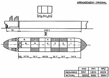
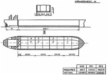
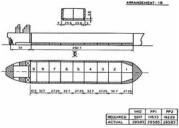
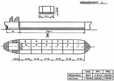
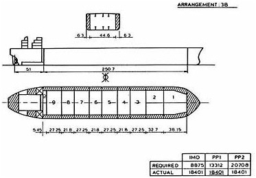


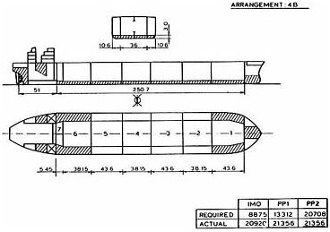

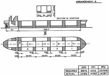
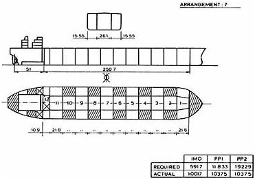
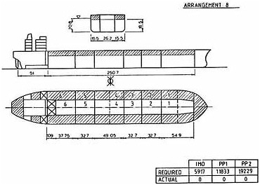
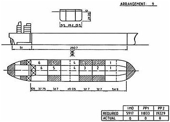
Fig.3.13. Hydrostatically Balanced Loading (9)
Intact stability, still water bending moments and shear forces have been calculated for designs 1A, 3 and 7. For 1A the damage stability calculations have been performed as well. The results are presented in Appendix 3.
An estimation of the steel weight has been carried out for all VLCC designs. The results are given in Appendix 3.
3.2 Ranking of VLCC Designs
Due to the simplifications and generalisations made above, and to shortcomings in the statistical information, the results from this study should be used for ranking the different VLCC designs only.
In the analysis the specific gravity for crude oil is assumed to be 0.9 t/m3. At this gravity the ship will float deeper than the design draught. The influence of various specific gravities on oil outflow has been examined.
3.2.1 Ranking in Collision
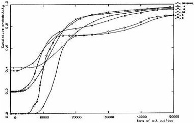
The results from the PROBAN analysis are shown in Fig.3.14–3.16.
gives the probability for the escaping amount of oil to be equal or less the amount shown on the abscissa.
Double side as protective barrier against oil outflow is clearly demonstrated in Fig.3.14. In appr. 40% of all collisions resulting in rupture of the hull plating, no oil will escape at all for designs 3B and 5 as the inner side remains intact. Similarly, designs 1A and 1B will not leak oil in appr. 20% of all collisions resulting in rupture of hull plating.
Once the double side is ruptured, however, rather much oil is expected to escape in both 3B and 5 due to short tanks: the probability of penetrating several cargo tanks in collision is imminent.
The influence of cargo tank size on the potential oil outflow in collision for double side designs is also illustrated when comparing curves for 1A and 1B with each other: in 75% of all collisions design 1A with longer tanks is likely to leak significantly less oil than the same design 1B with short tanks.
As for single side VLCCs (Fig.3.15), 4B performs rather well and the oil outflow is quite limited for up to 60% of all collisions. For the rest of collisions the potential for oil outflow is quite high. This particular design has ballast side tanks immediately aft of the collision bulkhead which, considering the collision statistics used, explains the good performance in most collisions.
Best performance in all collisions is shown by design 7, with small cargo and ballast tanks. The ballast tanks provide a very effective protective barrier reducing the amount of oil likely to escape.
Considering the Intermediate Oil Tight Deck VLCC, this design performs similar to design 2 in about 70% of collisions, but clearly poorer for the rest of collisions. The reason for the difference is that at higher probability level the centre tanks are likely to be punctured, and as these contain only crude, then the potential oil outflow will increase much compared to design 2.
When loading the original VLCC SBT hydrostatically the potential oil outflow is reduced with an amount which corresponds to the difference in cargo quantity carried. The volume escaping remains the same as in the original VLCC SBT.
In order to rank all designs w.r.t. oil outflow in collision, the curves in Fig.3.14 and 3.15 have been integrated for accumulated probability of 0.0 to 0.9, and compared with the original VLCC (index=100). The reason for not integrating up to 1.0 is that the curves flatten out between 0.9 and 1.0, and the smoothening of the curves may introduce excessive errors influencing the index. In addition, the uncertainties associated with the different outflow model parameters will have a rather strong effect at this probability level reducing the validity of results.
The resulting ranking is shown in Fig.3.16. It shows that designs 5(double side, partial double bottom) and 7(small tanks) leak about 25% less oil than 1A and 1B(double side, double bottom), and about only a third of the oil escaping from the conventional modern VLCC. Designs 6, 8 and 9 do not perform that well.
It is strongly stressed that the potential amount oil shown escaping in the results, is a weighed mean of the total amount oil contained in the cargo tanks damaged. In reality, the amounts are likely to be significantly lower as tanks might not wholly be ruptured from bottom to top due to actual bow forms, and as possible pollution preventive measures such as cargo transfer to other tanks may be initiated by the crew.
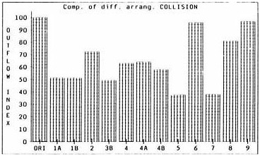
Fig.3.16. Ranking of VLCC Designs w.r.t. Oil Outflow in Collision
3.2.2 Ranking in Grounding
Extrapolating the calculated damage height mean for B/15(= 3.813) gives the damage height mean used in the PROBAN runs VLCCs as 2.308 with a standard deviation of 1.452.
As no supporting values on the damage height for grounded VLCCs have been available, the extrapolated damage height used in this analysis might be too high reducing the positive influence of double bottom height on the amount of oil escaping.
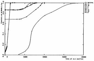
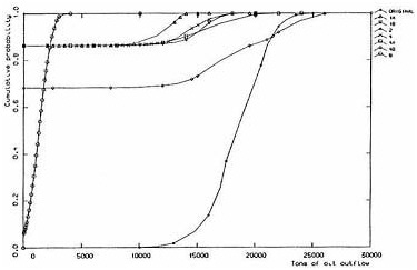
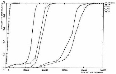
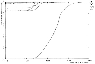
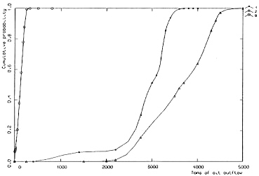
The results from the PROBAN analysis are shown in Fig.3.17-3.24. The cumulative probability on the ordinate in Fig.3.19-3.22 gives the probability for the escaping amount of oil in grounding to be equal or less than the amount shown on the abscissa at a grounding speed of 5 kn (Fig.3.19-3.20) and 10 kn(Fig.3.21-3.22).
Fig.3.19 and Fig.3.21 clearly show the merits of a double bottom w.r.t. reducing the amount of escaping oil. In some 85% of all groundings no oil is likely to escape from designs 1A, 1B, 4 and 4A having a double bottom of 3.9 m. For design 2, with a double bottom height of 6.6 m, this figure is not less than 99.8%!
The intermediate oil tight deck does not completely stop oil outflow in grounding; - groundings damaging the ship bilge and side will always result in oil outflow. A double bottom will protect against most of these damages.
The same conclusion applies to a hydrostatically loaded VLCC, due to possible bilge and side damage in grounding it will always leak some oil. Should design 3B be hydrostatically loaded, virtually no oil would leak in grounding as the probability for the bilge damage extending to the cargo tank is extremely small.
On the other hand, should the double bottom be penetrated, rather much oil will escape due to rather long damage lengths even at moderate grounding speeds. This is shown by the horizontal part of the oil outflow curves in 3.19 and 3.21.
A double bottom VLCC with hydrostatically filled cargo tanks will perform well in grounding. The double bottom will protect against bilge damage, and should the bottom be punctured, then the bottom will be filled with water. If the tanks are filled to a level corresponding to hydrostatic balance plus double bottom height, then some oil may escape in grounding due to mixing of water and oil.
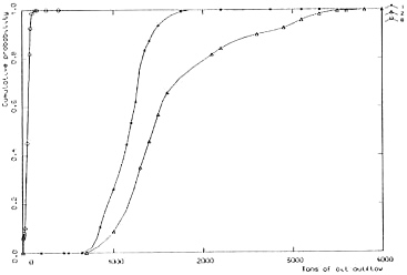
In Fig. 3.17 - 3.18 the damage lengths have been calculated based on Eq. 3.3 and 3.4 for a grounding speed of 5 and 10 kn respectively. An increase in the grounding speed to 10 kn will result in the damage length reaching 100 m and more; - several tanks will be damaged in single bottom ships, or when the double bottom height is insufficient.
From the figure the influence of increasing the double bottom height on the damage length is evident: - as the height goes up, so goes the damage length i.e. the less influence will the inner bottom have on absorbing kinetic energy. For double bottom heights of 5 m and above, no kinetic energy is absorbed by the inner bottom given the damage heights used in this study.
This is illustrated in Fig.3.20 and Fig.3.22. All VLCCs without a double bottom seem to leak quite much oil should they run aground. Designs 3B and 5 perform both much worse than the conventional VLCC in grounding. This is due to wide and relatively short cargo tanks in 3B and 5; - once running aground much crude oil will escape as the ballast side tanks are quite narrow.
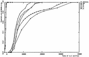
The analysis shows that the partial double bottom in design 5 seems to be somewhat short and too low in order to be effective against oil outflow in grounding.
Considering the influence of speed at grounding on the oil outflow, the curves in Fig.3.19 and 3.21, and in Fig.3.20 and 3.22 respectively, indicate a doubling in the potential amount of oil escaping in grounding as the speed increases from 5 to 10 kn at the same probability level.
A sensitivity analysis has been performed in order to assess the influence of rock shape on damage extent showing that if the breadth of damage is halfed, the damage length at 5 kn will be approach the results obtained above for 10 kn.
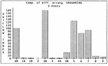
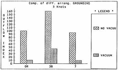
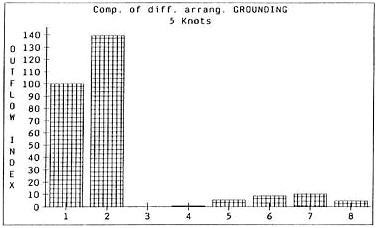
In Fig.3.23 the average oil outflow index is given for groundings at 5 kn. The index is for each design is obtained by integrating the curves in Fig. 3.19-20 from 0.0 to 0.9, and comparing with the original VLCC.
Again, the double bottom designs 1A, 1B, 2, 4 and 4A show their good overall resistance against oil outflow in grounding. The intermediate oil tight deck design and the hydrostatically loaded tanker perform almost as well. The inferior designs 3B and 5 are likely to leak appr. 60% and 25% more oil respectively than the conventional VLCC in grounding.
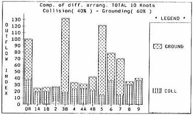
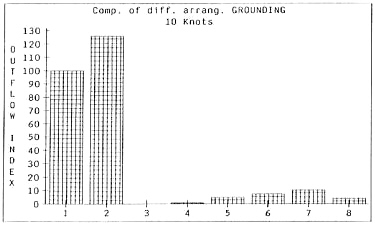
Fig.3.24 gives the corresponding oil outflow index for 10 kn. As speed is increased, the cumulative probability for no leakage remains the same but because the damage length is increased so is the amount of oil likely to escape. One observes that the intermediate oil tight deck design as well as the hydrostatically balanced tanker now perform slightly better than designs 1A, 1B and 4, 4A. This is due to the more pronounced speed sensitivity of the latter designs (see Fig.3.21).
The influence of specific gravity on potential oil outflow has been studied for the original VLCC in grounding at 10 kn. When the gravity is 0.85 t/m3, the potential oil outflow index is reduced by some 20%.
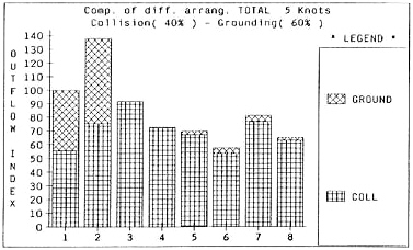
3.2.3 Combined Ranking – Collision and Grounding
An analysis of serious collision and grounding casualties carried out by DnVC for tankers above 20,000 tdw shows that the probability for collision casualties is appr. 40% and for groundings appr. 60% on a world wide basis.
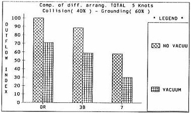
Using these percentages, the average oil outflow for different designs in collision and grounding respectively have been combined in Fig.3.25 for 5 kn grounding speed, and in Fig.3.26 for 10 kn grounding speed. In the figures, the total index has been given as well as the parts from collision and grounding.
From Fig.3.25 it may be concluded that the double side/double bottom designs 1A and 1B provide the best overall protection

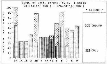
against oil outflow. Designs 4 and 4A are almost as good as designs 1A and 1B.
The wide side tank, single bottom design 3B performs worse than the conventional VLCC at high grounding speeds as does the partial double bottom design 5. At low grounding speeds, the performance of the partial double bottom design is much improved.
Design 7 with 50% MARPOL tank sizes is likely to leak some 35-40% less oil on the average in case of collision and grounding.
The combined index for, the intermediate oil tight deck design suffers from bad collision performance. At 10 kn, this design leaks only some 35% oil compared to the original VLCC but 40% more than designs 1A, 1B and 2.
3.2.4 Impact of a Vacuum System on Oil Outflow in Grounding
The impact of a vacuum system1 on the oil outflow has been calculated for the conventional VLCC and the single bottom designs 3B and 7 respectively at a grounding speed of 5 kn.
It is assumed that the vacuum system is able to keep the vacuum in 40% of the total tank volume. Should more than 40% of the total tank volume be damaged, it is assumed that the first 40% of the damaged tanks keep the vacuum, and that the oil contained in subsequent tanks damaged will escape until hydrostatic balance is reached in the tanks.
The results are shown in Fig.3.27. For the conventional VLCC and design 7, the oil escaping is reduced to some 11%, for design 3B to about 29%.
The average oil outflows in collision and grounding with vacuum have been combined using above weights; – the results are shown in Fig.3.28. Comparing these values with corresponding values in Fig.3.25 shows that design 7 with vacuum is likely to perform as well as the double skin designs 1A and 1B, except that in 85% of the groundings no oil will escape from 1A and 1B at all whereas there always will be some oil leakage from a single bottom VLCC with the vacuum system fitted in the cargo tanks.
It is interesting to note that a conventional VLCC fitted with a vacuum system is likely to reduce its overall average oil outflow by half as compared with the basic design without the vacuum system. However, even with the vacuum system fitted, the VLCC is likely to leak about twice the amount of oil when compared with the double skin designs 1A and 1B.
3.3 Conclusions and recommendations
The study shows that the double side/double bottom VLCC designs (1A, 1B) have the smallest potential for oil outflow in collision and grounding with the given assumptions regarding damage location and extent respectively. Compared with a modern conventional VLCC the double side/double bottom VLCC is likely to leak on the average only about 33% of the corresponding amount of oil.
Comparing double side/double bottom designs, the design with two longitudinal bulkheads in addition to the double side(1A), is likely to leak less oil in about 75% of all collisions than the design with only one longitudinal bulkhead at the centreline (1B) although both designs have the same overall performance.
The amount of oil likely to escape from a VLCC with double bottom for ballast and with segregated ballast side tanks(4, 4A and 4B), is about 40% of the amount oil a modern conventional VLCC may leak under the same conditions. The positive influence of locating the ballast tanks forward in the side tanks on potential oil outflow in collision is evident (4B vs. 4A).
As for single bottom designs with wide wing tanks for ballast (3B), their overall performance i.e. combined ranking, is quite poor due to large amount of oil likely to escape in grounding. In fact, they perform only slightly better than modern conventional VLCCs.
Reducing the tank size to half of MARPOL requirements(7) reduces the potential average oil outflow to about 60% as compared with the conventional VLCC.
The partial double bottom VLCC(5) analysed does not perform too well in grounding; - the basic reason is that the double bottom height is too low in order to be effective against oil outflow in grounding under the assumptions made in the study. Increasing the double bottom height, and reducing the side tank width, brings the results for design 5 closer towards those of 1A and 1B. Considering mud or sand bottoms, design 5 might be attractive because of reduced damage lengths.
It should also be stressed that in about 85% of all groundings the double bottom designs studied leak no oil at all, whereas always some oil will leak from single bottom designs irrespective of tank size and the ship having a vacuum tank system or not.
A vacuum system reduces significantly the amount of oil escaping in grounding for the single bottom designs analysed. However, the total amount of oil escaping from the modern conventional VLCC with a vacuum system is still about twice the amount escaping from the double side/double bottom design in case of collision and grounding.
Comparing VLCCs with double sides to VLCCs with single sides, the the double side provides an effective barrier against oil outflow
in 20% of the all collisions for designs 1A and 1B, and in 42% of all collisions for 3B. The protection is particularly efficient for low-energy collisions with limited damage penetration.
The influence of increasing the double bottom height as compared with increasing the double side width on oil outflow is shown in Table 3.3.1.
From the Table one may observe that increasing the double bottom height from 2.0 to 3.9m(B/15) reduces the probability for oil outflow in grounding from 58% to 14%, and increasing the width of double side from 2.0 to 3.0 m reduces the probability for oil outflow in collision from 88% to 80% only. Introducing the above zero outflow values for 2.0 m double bottom and double side into Fig. 3.14 and 3.24, and integrating assuming the curves follow those for design 1A and 1B, one obtains the outflow index for collision as ˜59 and grounding as ˜61. Combined index is ˜60, or about 2.4 times the index for 1A.
Table 3.3.1. Probability for NO oil leakage as function of double bottom height and distance between double sides
|
GROUNDING |
|
|
DIST. BETWEEN INNER/OUTER BOTTOM |
PROBAB. FOR NO LEAKAGE |
|
2.0 M |
41.7 % |
|
2.4 M |
52.6 % |
|
3.0 M |
69.0 % |
|
3.9 M |
86.0 % |
|
6.6 M |
99.8 % |
|
COLLISION |
|
|
DIST. BETWEEN INNER/OUTER SKIN |
PROBAB. FOR NO LEAKAGE |
|
2.0 M |
12.1 % |
|
3.0 M |
20.4 % |
|
5.8 M |
39.4 % |
|
6.3 M |
42.0 % |
CONCLUDING FROM THE ABOVE ANALYSIS ON VLCC DESIGNS:
-
narrow and long cargo tanks, and increased double bottom height clearly reduces the oil outflow as does reduced tank volumes.
-
ballast forward in side tanks will reduce the potential oil spill in collision, and in low speed groundings
-
VLCCs should have a double bottom height approaching B/15 in order to be effective against pollution in grounding
-
in addition, double sides having a width of at least B/20 should be considered.
-
single bottom designs should preferably be fitted with a vacuum system in order to reduce the amount of oil escaping in grounding.
-
hydrostatic loading may be an alternative to vacuum systems, the lost cargo capacity is not prohibitive at A-freeboard. The increased draught may create problems in coastal waters and loading/discharging terminals.
-
intermediate oil tight decks may be effective against oil pollution if adequate collision protection is provided.
-
low L/D ratios (≃ 10) contribute to excessive pollution in grounding due to high freeboard. A higher L/D ratio (≃ 12) would significantly reduce the amount of oil escaping in grounding.
SEE COMMITTEE COMMENTS ON DNV CONCLUSIONS FOR VLCCS ON PAGE 300.
4.
PROBABILISTIC RANKING OF 40,000 DWT TANKERS
4.1 The 40,000 dwt Designs Analysed
The 40,000 dwt designs chosen for the analysis are essentially similar to the VLCCs the objective being to detect trends in the results obtained which would be valid for other tanker sizes as well.
Of particular interest has been to investigate the influence of double side width on oil outflow as several 40,000 dwt product tankers have been built with narrow sides.
4.1.1 General Features
All designs analysed have following main particulars:

Following parameters have been kept constant:
-
the length of the cargo area = 143.0 m
-
tank lengths (except design 7) = 28.0 m
-
ballast capacity outside the cargo area ≅ 3000 m3
-
slop tank volumes ≅ 800 m3
-
deadweight ≅ 46,500 tons.
The specific gravity for oil is taken as 0.9 t/m3. For designs with less ballast in the cargo area than the original 40,000 dwt tanker, the increased cargo volume has not been utilized due to constant deadweight assumption. Resulting possible slack in oil tanks (if oil level in tank < .98D) has been assumed equally distributed on all crude oil tanks. At lower specific oil gravities the excess tank volume may be utilized without exceeding the design draught.
MARPOL/2/ requirements to tank lengths have been considered as have requirements to tank sizes.
4.1.2 Particulars of 40,000 dwt Tankers
The numbers below refer to the designs shown in Fig.4.1-4.8, and to graphs showing the potential oil outflow which has been calculated for different designs. A fold out page showing the designs has been enclosed at the end of the report.
The box in the lower right hand corner in Fig.4.1-4.8 shows IMO requirements, and DNVC PP1, PP2 and PP3 requirements. The actual values have been included.
-
Modern 40,000 tdw SBT
Cargo capacity for this design is ˜ 52700 m3. The ballast capacity in the cargo area is ˜ 17,000 m3.
The ballast/cargo ratio is 0.38 which is rather high for a single skin tanker.
This design barely meets the IMO requirements and is short of meeting the DNVC PP1, PP2 and PP3 requirements.
-
Double sides and single bottom
All ballast in the cargo area is carried in the double side. The width of the double side is 3.0 m(˜B/9). Wide tanks.
The ballast capacity in the cargo area is ˜ 15,100 m3.
-
Double bottom and single sides
All ballast is carried in the double bottom which has a height of 3.9 m(˜B/7). A centreline bulkhead has been fitted.
The ballast capacity in the cargo area is ˜ 15,500 m3.
-
Narrow double sides and double bottom
This design complies with the IMO Chemical Code Type 2/9/ships w.r.t. the width of double side i.e 0.76 m. Double bottom height is 2.6 m. Centreline bulkhead is fitted.
The ballast capacity in the cargo area is ˜ 13,600 m3.
-
Double sides and double bottom
The double sides are 1.2 m apart. The height of the double bottom is 2.0 m. Centreline bulkhead.
The ballast capacity in the cargo area is ˜ 13,600 m3.
-
Wide double sides and double bottom
The double side width is 2.0 m. The height of the double bottom is 1.83 m(B/15). Centreline bulkhead.
The ballast capacity in the cargo area is ˜ 16,300 m3.
-
Wide double sides and double bottom, short tanks
This design features the same double side width and double bottom height as design 6. The difference is that design 7 has no centreline bulkhead and short tanks (20 m).
-
Intermediate Oil Tight Deck
An intermediate oil tight deck has been fitted 8.9 m above the baseline. The side tanks have the same width and length as the original 40,000 dwt tanker.
4.2 Probabilistic Ranking of 40,000 dwt Tankers
The same procedure for estimating oil outflow in collision and grounding has been adopted for 40,000 dwt tankers as for the VLCCs. The same statistics have been used but weighed for the smaller tanker i.e. the extent of damage depth, breadth and height have been related to the main particulars of the 40,000 dwt.
4.2.1 Ranking in Collision
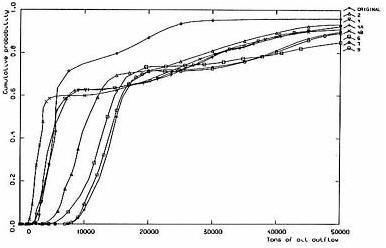
The results from the PROBAN analysis are shown in Fig.4.9-4.11.
The very good performance of the original design is not surprising due to the location of the long and wide ballast tanks in the bow. These tanks provide an extremely efficient protection against collision.
The influence of double side width on oil outflow is evident from Fig.4.9 - in 42% of all collisions will no oil escape from the 40,000 dwt with 3 m wide double tanks carrying only ballast. Once the inner side is punctured rather much oil will escape however. This is the drawback of having no centreline bulkhead and long cargo tanks.
This is supported by studying the curves for oil outflow from designs 6 and 7 having the same double side width. Design 6 with long tanks and a centreline bulkhead performs much better after the inner side has been punctured; - at 0.8 probability level the short tank design is likely to leak ∼66% more than the centreline bulkhead design.
In 9 % of all collisions resulting in structural damage, the narrow double side of 0.76 m will not leak any oil. The narrow double side provides protection against oil outflow especially at low velocity quay contacts. The impact of the centreline bulkhead on oil outflow is obvious when compared to the wide double side design above.
Comparing the original tanker with double side tankers one observes from Fig.4.9 that although the original tanker will always probably spill some oil in collision, the tanker will spill relatively little in more than 60% of all collisions.
The poor collision behaviour of the double bottom tanker is expected.

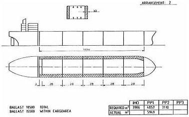
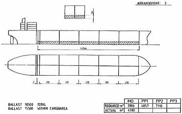
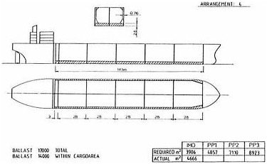
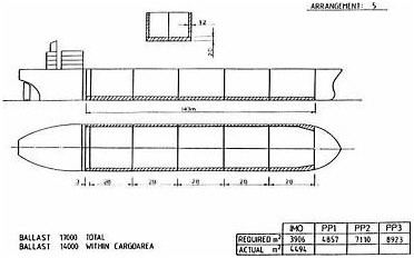
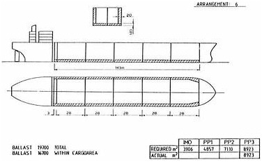
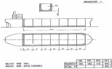
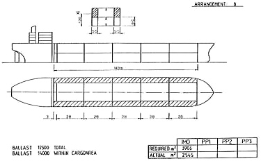


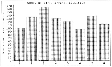
Fig.4.11. Ranking of 40,000 dwt Tankers in Collision
The 40,000 tdw tanker with an intermediate oil tight deck performs overall slightly worse than double side tanker with centreline bulkhead (design 6) and the original. Under the assumptions made regarding the vertical extent of collision damage, it will always leak some oil in collision.
Integrating the outflow curves in Fig.4.9–4.10, and comparing with the original design shows (Fig.4.11) that the only design that can match the original design is design 6 – the wide double side and double bottom design with long tanks and centreline bulkhead (outflow index 98). In comparison, the wide double side design(7) with short tanks has an index of 140.
The narrow double side design(4) has an index of 130, this design performs better than design 7 which has about three times wider side tanks. Tank length seems obviously to have larger influence on oil outflow in collision than the width of the double side.
4.2.2 Ranking in Grounding
The results from the PROBAN analysis are shown in Fig.4.12–4.17.
The original 40,000 dwt tanker performs quite badly in grounding even at low speeds. This is because L/D is quite low, – in case of grounding (assuming hydrostatic equilibrium in a damaged tank) about 25% of the oil in the damaged tank will escape. The tanker with ballast in side tanks only, design 2, performs even worse.
Comparing the oil outflow curves for the original 40,000 dwt for 5 and 10 kn respectively, one observes that at 5 kn the curve is rather steep. This indicates that ballast in forward side tanks combined with long cargo tanks reduce the oil outflow at low speed grounding. At 10 kn, the oil outflow curve is rather horizontal at the beginning implying that there is a low probability for the damage to be restricted to the bow area only.
The performance of the original 40,000 dwt tanker and design 2 would improve much should they be fitted with a vacuum system, or be hydrostatically loaded. An alternative for design 2 may be to fit a double bottom in the cargo area only.
All double bottom designs perform quite well in grounding. Designs 3 and 4, with a double bottom of 3.9 and 2.6 m respectively, are likely to leak no/almost no oil at all in grounding. In more than 80% of all groundings, the B/15 double bottom of 1.83 m will provide protection against oil outflow (designs 6 and 7). Double bottoms restrict the potential oil outflow in case of bilge and side damage due to grounding.
Due to lack of time, the influence of double bottom height and ship speed on damage length in grounding has not been established for 40,000 dwt tankers.
As expected the intermediate oil tight deck tanker performs quite well in grounding.
Integrating the curves in Fig.4.12-4.13 gives the average oil outflow index in grounding at 5 kn. All designs, except design 2, have an index below 10 (Fig.4.14).
The effect of increasing grounding speed on potential oil outflow is similar for 40,000 dwt tankers as for VLCCs. The results are shown in Fig.4.15-4.17. At 10 kn, all designs except design 2, have an index below 10.
Carrying oil with a lower specific gravity would result in the ship draught either being reduced or remain about the same when utilising the excess tank capacity. Assuming a specific gravity of 0.7 t/m3, the new draught for the original 40,000 dwt would be in the order of 10.5 m. This would cause the potential oil outflow to be reduced by some 35% in grounding. For the other designs volume spilled may increase when filling up tanks with light products; - the difference in potential oil outflow has not been calculated.
The hydrostatically loaded 40,000 dwt tanker would, due to same damage statistics as for the VLCCs, leak some oil in grounding because the bilge and side may be damaged in grounding.
In case of a tanker with double bottom being hydrostatically loaded, the hydrostatic balance level may be increased with an amount equal to the double bottom height. Should the double bottom be damaged, then water and oil will fill the double bottom. Some oil outflow may occur to oil mixing with water in the damaged double bottom.
Should the tanker be part loaded then the oil outflow in grounding would be reduced significantly.

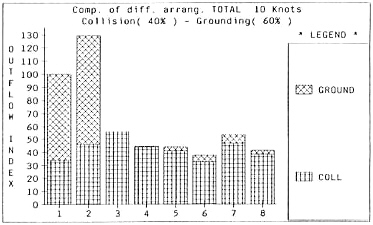
4.2.3 Combined Ranking
Combining the above indices for collision, and grounding at 5 and 10 kn respectively, using a 40–60 collision/grounding weighing gives the combined ranking shown in Fig.4.18 for 5 kn grounding speed and in Fig.4.19 for 10 kn grounding speed.
At 5 kn, design 6 with wide double side and low double bottom obtains an index of ˜57 followed by design 8 having an index of ˜65. Only design 2, the one without double bottom, has an index above the original 40,000 dwt tanker.
The ranking does not change for 10 kn; – design 6 is still best with an index of ˜38 followed by designs 8, 4 and 5.
4.3 Conclusions and Recommendations
The above analysis for 40,000 dwt tankers shows the importance of double bottom on the potential oil outflow. In Table 4.3.1, the effect of increasing the double bottom height and width of double side on the probability for leaking no oil is given respectively.
The Table shows that the probability for oil leaking is reduced rapidly as double bottom height is increased.
For collisions, increasing the width of the double side has not the same dramatic effect on the probability for no oil outflow.
Table 4.3.1. Probability for no oil outflow in collision and grounding
|
GROUNDING |
|
|
DIST. BETWEEN INNER/OUTER BOTTOM |
PROBAB. FOR NO LEAKAGE |
|
1.83 M |
85.1 % |
|
2.0 M |
90.0 % |
|
2.6 M |
98.4 % |
|
3.9 M |
99.99% |
|
COLLISION |
|
|
DIST. BETWEEN INNER/OUTER SKIN |
PROBAB. FOR NO LEAKAGE |
|
0.76 M |
8.6 % |
|
1.2 M |
16.3 % |
|
2.0 M |
29.2 % |
|
3.0 M |
41.9 % |
CONCLUDING FROM THE ABOVE ANALYSIS ON 40,000 DWT TANKERS:
-
narrow and long side tanks reduce the potential oil outflow in collision and grounding as does reduced tank volumes.
-
introducing a centreline bulkhead reduces the potential oil outflow in collisions when compared with short wide cargo tank designs.
-
for ships ‹ 50,000 dwt, the width of double side could be related to B/25 with a minimum of 760 mm according to the Chemical Code Type 2 ships in order not to reduce the cargo capacity (ref. limited influence of increased width on oil outflow), and allowing for centreline bulkheads.
-
double bottom provides an effective barrier against oil pollution for the 40,000 dwt tankers analysed. The height of double bottom should not be less than B/15.
-
double bottoms reduce oil outflow in groundings causing bilge and side damage
-
single bottom designs should be fitted with a vacuum system, alternatively loaded only to a hydrostatic balance level to reduce oil outflow in grounding.
-
the intermediate oil tight deck design performs quite well but will always leak some oil in collision and grounding
SEE COMMITTEE COMMENTS ON DNV CONCLUSIONS FOR 40,000 DWT TANKERS ON PAGE 301.
5.
ESTIMATED OIL OUTFLOW FROM A 80,000 DWT TANKER
Based upon above studies for VLCCs and 40,000 dwt tankers, the potential oil outflow from a 80,000 dwt is discussed in this Chapter. No supporting calculations have been carried out with PROBAN.
5.1 Comparison of Performance for VLCCs vs. 40,000 dwt Tankers
Original VLCC and 40,000 dwt tanker designs – single skin:
The smaller tanker with large ballast side tanks forward performs relatively much better than the VLCC design which is penalised for not having ballast in the same side tanks.
The high ballast/cargo volume ratio for the 40,000 dwt necessarily improves the performance of the original design in relation to other 40,000 dwt designs.
Comparing the potential oil spill volume to total cargo volume ratio, the difference is only ˜ 1.3% in ratios for the VLCC and the 40,000 dwt tanker.
In grounding, the overall performance is rather poor for both the VLCC and the 40,000 dwt tanker. Again ballast in forward side tanks reduces the oil spill, but due to long damage lengths at 10 kn, the effect is not very pronounced.
Ballast in forward side tanks reduce also the potential for oil spill in bilge and side damages caused by grounding; – at low grounding speeds the reduction is considerable.
The volume of oil spill in grounding in relation to total cargo volume is virtually the same for the VLCC and the 40,000 dwt tanker at 5 and 10 kn respectively. At 10 kn, the total amount oil both ships leak is 2.5–3 times more than at 5 kn.
A vacuum system will reduce the oil outflow in grounding by ˜90% at 5 kn provided a vacuum can be maintained in 40% of the cargo tanks. At 10 kn the relative reduction will be smaller because damage lengths increase and more tanks are damaged. Increasing the vacuum capacity will reduce the oil outflow correspondingly.
Hydrostatically balanced loading of cargo tanks will reduce oil outflow in grounding to less than 10% of the original amount.
For a 80,000 dwt SBT tanker with conventional tank arrangement, much the same behaviour is expected.
Double side and double bottom designs:
Oil outflow from VLCCs with double sides and double bottom is radically lower compared with the VLCC SBT – the overall oil outflow is ˜33% of the outflow from the VLCC SBT at 10 kn. For the 40,000 dwt tanker the corresponding percentage is ˜37 at 10 kn.
The same reduction in overall oil outflow may be expected for a 80,000 dwt tanker provided the ship meets with the B/20 double side and B/15 double bottom recommendations.
Double sides and single bottom designs:
In the VLCC and the 40,000 dwt tanker with double sides and single bottom, the double side width is appr. B/9. The probability for no oil outflow in collision is for both ships ˜42.0%.
Both ships perform rather poorly in grounding. The VLCC is likely to leak 80% more than the VLCC SBT at 10 kn. The 40,000 dwt tanker 25 % more than the original 40,000 dwt tanker.
A vacuum system reduces the potential oil spill in grounding at 5 kn for the VLCC by ˜70 %. Increasing the speed results in relatively more oil spill due to increased damage lengths.
Hydrostatically balanced loading of cargo tanks would virtually eliminate all oil outflow in grounding as the probability for a bilge damage to extend into the cargo tanks is very low(assuming double side width B/9 as above).
For the 80,000 dwt tanker, the oil spill in grounding may be 35–40% in comparison. This value depends on the L/D ratio for the design.
Single side and double bottom designs:
In collision, the 40,000 dwt tanker with ballast in double bottom only, leak considerably more than the original design. The increase in total oil outflow is some 65 % in spite of the ship having a centreline bulkhead and long tanks.
In case of the VLCC, the single side/double bottom design is likely to leak ˜30% less than the original VLCC. As stated above, the reason for poor behaviour of the original VLCC is due to no ballast in forward side tanks.
In grounding neither the VLCC(B/dbh = 8.6) nor the 40,000 dwt tanker(B/dbh=7.0) is expected to leak any oil.
For a similar 80,000 dwt tanker no difference in performance is expected.
Intermediate Oil Tight Deck Designs:
In collision, the performance of the intermediate oil tight deck design is a little better for the VLCC and a little inferior for the 40,000 dwt tanker.
In grounding, the performance is good for both sizes.
For the 80,000 dwt, the same behaviour is expected.
5.2
Conclusions and Recommendations:
Following general conclusions may be drawn regarding oil outflow from a 80,000 dwt tanker:
-
long and narrow tanks are likely to leak less than short and wide tanks. A centreline girder should be fitted to reduce oil outflow in collisions
-
a double bottom of B/15 should be fitted, an alternative may be a vacuum system with high capacity or hydrostatic loading of cargo tanks
-
a double side should be considered to restricted pollution in low-energy collisions; preferred width B/20
-
high L/D reduces oil outflow in grounding
SEE COMMITTEE COMMENTS ON DNV CONCLUSIONS FOR THE 80,000 DWT TANKER ON PAGE 302.
6.
SUMMARY OF RESULTS
The results should strictly be used only for ranking the VLCC and 40,000 dwt tanker designs as the statistics for damage extent used contain all types and sizes of ships. In addition, some simplifications have been made in the study influencing structural response in collision and grounding.
The adopted procedure for assessing the potential oil outflow in collision and grounding seems promising, however, Provided more detailed statistics is applied for tanker damages, the results would improve.
Summing up conclusions in Chapters 3–5, following measures should be considered for reducing the probability for oil outflow in collision and grounding:
-
a low L/D ratio will increase oil outflow in grounding
-
wide tanks are likely to spill more oil than long narrow tanks
-
location of ballast forward in side tanks provides good collision protection
-
double side protects against oil outflow in low-energy collision
-
width of double side should tentatively be B/25 for ships ‹ 50,000 dwt, and B/20 for ships above, in order to be effective in ship/ship collision
-
double bottom reduces oil outflow in grounding
-
double bottom protects against bilge and side damage in grounding
-
the double bottom should tentatively be B/15
-
vacuum systems reduce oil outflow in grounding
-
hydrostatic loading of cargo tanks reduces oil outflow in collision and grounding
-
intermediate oil tight deck reduces oil outflow in grounding
REFERENCES
/1/ PROBAN Theory Manual, Veritas Research 1986
/2/ IMO International Conference on Marine Pollution 1973
/3/ IMO Regulations on Subdivision and Stability of Passenger Ships, Resolution A.265(VIII)
/4/ Valsgård, S. – Jørgensen, L.: Evaluation of Ship/Ship Collision Damage Using a Simplified Nonlinear Finite Element Procedure, Int. Symp. on Practical Design in Shipbuilding PRADS'83, Tokyo/Seoul, 1983
/5/ Køhler, P.E. – Jørgensen, L.: Ship Ice Impact Analysis, 4th Int. Symp. on Offshore Mechanics and Arctic Engineering OMAE, Dallas, 1985
/6/ Vaughan, H.: Bending and Tearing of Plate with Application to Ship Bottom Damage, The Naval Architect, May 1978
/7/ Wierzbicki, T. et. al.: Damage Estimates in High Energy Grounding of Ships, MIT, June 27, 1990
/8/ Køhler, P.E. et. al.: Potential Oil Spill from Tankers in Case of Collision and/or Grounding – A Comparative Study of Different VLCC Designs, DNVC Report 90–0074, May 1990
/9/ IMO International Code for the Construction and Equipment of Ships Carrying Dangerous Chemicals in Bulk, London 1986
INTERPRETATIONS AND COMMENTS OF THE COMMITTEE ON TANK VESSEL DESIGN CONCERNING SECTIONS OF THE DET NORSKE VERITAS REPORT
Following are the committee's interpretations of the most significant assumptions in the collision analysis. Statements drawn from the DnV report are in italics (some excerpts have been edited for brevity and style), and committee comments are in standard type.
DNV Collision Assumptions (Section 2.1.1)
Several simplifying assumptions were made with respect to the collision assessment. To avoid overly optimistic results, the assumptions were conservative. Therefore, the committee feels that outflow may be overstated on a consistent basis.
The study assumes that oil begins to escape from a cargo tank when the bow of the striking ship touches a side or corner of the tank. No large deformations resulting in yielding of the tank sides were required. Thus, a tank is considered penetrated at contact.
The striking bow is assumed to be wedge-shaped, and it remains in shape after penetrating hull plating. As the vertical bow penetrates a tank, the full height of the tank is ruptured, from bottom to top. This assumption was made to conform with the MARPOL assumption that all oil will escape from a damaged tank over time.
One consequence of these assumptions is that the results apply strictly to the final condition — that is, after all oil has escaped from a holed tank. To obtain more accurate estimates on oil outflow during the collision, it would be necessary to conduct detailed modeling of bow crushing behavior and ship side structural response during the collision process, taking into account the changes in ship speeds and headings, and added mass effects. This is beyond the scope of the present study. Furthermore, the committee feels that additional research would be required even to develop the capability to obtain these estimates.
In the present study, only damage in way of the collision contact point is considered. Damage elsewhere, such as possible tearing in weld seams due to excessive tension (potentially resulting in oil leakage), have not been considered.
As for possible explosions due to friction heat and sparks generated in a collision, the study assumes that the inert gas system is effective and no fires ensue.
Grounding Assumptions (Section 2.2.1)
Following are the committee's interpretations of the most significant assumptions in the DnV grounding analysis. Statements drawn from the DnV
report are in italics (some excerpts have been edited for brevity and style), and committee comments are in standard type.
The simplifying assumptions relate to extent of damage and oil outflow. Again, the assumptions are conservative, so outflow may be overstated consistently.
The analysis assumes that the grounding ship has forward speed, so that the damage is initiated at the bow and develops towards the stern. Damage caused by grounding while the ship is adrift, turning, or going astern, has not been considered.
The bottom surface is defined as a solid rock, which does not crush during the grounding process. The rock is assumed to be wedge-shaped (triangular in the transverse plane), with a constant breadth. The Vaughan method outlined in Chapter 3 was used in this analysis.
For purposes of this study, the hull plating is considered penetrated when the rock comes into contact with a tank side, bottom, or corner. Oil escapes until hydrostatic equilibrium is achieved in the damaged tank. Should the ship side be damaged, then all oil below the intact side plating will escape, to be replaced by water. Due to the reduced hydrostatic pressure, the oil level will drop proportionally to the specific gravities of water and oil, and the height of side damage.
Statistics on maximum vertical extent of grounding damage were applied to the full length of damage. This conservative assumption was made due to lack of detailed information on vertical damage extent, or penetration, as a function of damage length. Consequently, the damage lengths calculated may be too short, due to overstatement of the energy absorbed vertically.
Possible tearing of welds well away from the direct grounding damage have not been considered. Nor was the influence of ship motions during the grounding process considered in detail. During a grounding, a ship may develop a forward trim due to either downward suction of the bow, or sudden loss of buoyancy as the forward bottom plating is peeled off. Or, the ship may run up on the rock, lifting the bow. In this analysis, a variation in ship draft (+ 0.5 m) was included, partly to account for these factors.
Tidal effects on oil outflow were not considered. At low tide, more oil may escape from a ship sitting on a rock, due to reduced draft. Tides also may result in excessive hogging moments, which might result the hull breaking apart, with uncontrolled pollution. This matter requires a separate study, using available computer programs for ultimate strength analysis of the hull girder.
DNV Conclusions for VLCCs (Section 3.3)
Following are the committee's comments on each of DnV's conclusions for the VLCC designs. DnV conclusions are in italics, and the committee's comments are in standard type.
Narrow and long cargo tanks and increased double bottom height clearly reduces the oil outflow as does reduced tank volumes. The committee agrees.
Ballast forward in side tanks will reduce the potential oil spill in collision, and in low speed groundings. The committee agrees.
VLCCs should have a double bottom height approaching B/15 in order to be effective against pollution in grounding. The committee agrees, as one approach.
In addition, double sides having a width of at least B/20 should be considered. The committee prefers wider double sides.
Single bottom designs should preferably be fitted with a vacuum system in order to reduce the amount of oil escaping in grounding. The committee feels that the vacuum system needs further evaluation.
Hydrostatic loading may be an alternative to vacuum systems, the lost cargo is not prohibitive at A-freeboard. The increased draft may create problems in coastal waters and loading/discharge terminals. While the committee sees some benefit to hydrostatic loading, as noted in this statement, it perceives additional problems and feels hydrostatic loading should be considered for existing but not new vessels (except in conjunction with structural designs employing double hulls or double sides).
Intermediate oil-tight decks may be effective against oil pollution if adequate collision protection is provided. The committee feels that the intermediate oil-tight deck, when combined with double sides, shows promise and deserves further consideration.
Low L/D ratios (=10) contribute to excessive pollution in grounding due to high freeboard. A higher L/D ratio (=12) would significantly reduce the amount of oil escaping in grounding. The committee feels that high freeboard, not L/D ratio, is the relevant issue.
DNV Conclusions for 40,000 DWT Tankers (Section 4.3)
Following are the committee's comments on each of the DnV conclusions for the 40,000 DWT tankers. DnV conclusions are in italics, and committee comments are in standard type.
Narrow and long side tanks reduce the potential oil outflow in collision and grounding as does reduced tank volume. The committee agrees.
Introducing a centreline bulkhead reduces the potential oil outflow in collisions when compared with short wide cargo tank designs. The committee agrees but points out that centerline bulkheads may introduce possible asymmetric damage scenarios.
For ships over 50,000 DWT, the width of double side could be related to B/25 with a minimum of 760 mm according to the Chemical Code Type 2 ships in order not to reduce the cargo capacity (ref. limited influence of increased width on oil outflow), and allowing for centreline bulkheads. The committee prefers wider double sides.
Double bottom provides an effective barrier against oil pollution for the 40,000 DWT tankers analysed. The height of double bottom should not be less than B/15. The committee agrees that double bottoms are beneficial in terms of protection from groundings.
Double bottoms reduce oil outflow in groundings causing bilge and side damage. The committee agrees that double bottoms, as well as double sides, would reduce outflow.
Single bottom designs should be fitted with a vacuum system, alternatively loaded only to a hydrostatic balance level to reduce oil outflow in grounding. The committee feels that the vacuum system needs further evaluation and that hydrostatic loading should be considered for existing but not new vessels except in conjunction with structural designs employing double hulls or double sides. It does concur with the DnV conclusion that some oil leakage will occur if the hull is penetrated. The intermediate oil-tight deck with double sides will provide a reduction of outflow in high energy groundings.
The intermediate oil-tight deck design performs quite well but will always leak some oil in collision and grounding. The committee feels that the intermediate oil-tight deck, when combined with double sides, shows promise and deserves further consideration.
DNV Conclusions for the 80,000 DWT Tanker (Section 5.2)
Long and narrow tanks are likely to leak less than short and wide tanks. A centreline girder should be fitted to reduce oil outflow in collisions. The committee agrees with the benefits of long and narrow tanks and centerline bulkheads, but points out that centerline bulkheads may introduce possible asymmetric damage scenarios.
A double bottom of B/15 should be fitted, an alternative may be a vacuum system with high capacity or hydrostatic loading of cargo tanks. The committee agrees with the benefits of double bottoms in terms of grounding protection, but feels that the vacuum system needs further evaluation, and recommends that hydrostatic loading be considered for existing but not new tank vessels except in conjunction with structural designs employing double hulls or double sides.
A double side should be considered to restrict pollution in low-energy collisions; preferred width B/20. The committee prefers wider double sides.
High L/D reduces oil outflow in groundings. The committee feels that freeboard, not L/D ratio, is the relevant issue.


