
3
Physical Bases of Phenomena Active in Casualties
The preceding chapters have drawn a general profile of tank vessel activity worldwide, with particular regard to the United States. The report has presented, within an historical framework, the most up-to-date information available on tank vessel traffic, casualty patterns, basic design principles, and the regulatory system.
The report now turns to scientific and technical aspects of tank vessel design. This chapter describes the physical phenomena governing tankship and barge behavior with respect to the casualties described in Chapter 1. The intent is to provide basic insight into the laws of nature that must be considered in tank vessel design. Later chapters will expand upon the significance of these phenomena in designs aimed at preventing and/or ameliorating the oil spillage resulting from casualties. It is, perhaps, obvious that these discussions can be neither complete nor comprehensive.
Topics to be discussed in this chapter include: momentum exchange and energy dissipation in collisions and groundings; residual strength following damage; fires and explosions; corrosion and fatigue; hydrostatic pressures in opposition; and diffusion and dynamics of fluid/vessel motion.
STRUCTURAL AND DYNAMIC ASPECTS
Momentum Exchange and Energy Dissipation in Collisions and Groundings
In a collision or grounding, forces are generated that tend to bring the impacting bodies to the same velocity; or, in other words, to bring them to
rest relative to one another. When this occurs with forces so small that ship structure isn't damaged, then the kinetic energies involved, for the most part, are not dissipated. Instead, they are momentarily "stored" in the potential energy of elastically deformed structure, and the momentum exchange is completed when the deformed but intact structures "spring back" to their original shapes.
Unfortunately, the kinetic energies involved in most collisions and groundings are so large, compared to the potential energy that can be "stored" in elastic deflection of structure, that virtually all of this energy must be dissipated rather than exchanged. In groundings, there are four basic mechanisms of energy dissipation:
-
lifting of the ship against gravity forces;
-
frictional forces generated by rubbing of the hull against the grounding bottom;
-
forces involved in the plastic, i.e., permanent, shape distortion of the hull girder; and
-
forces involved in the fracture of structural material.
Although substantial friction forces often are generated as the structure of a penetrating vessel rubs against the ruptured structure of the stricken vessel, only the last two mechanisms listed above are available as major dissipation mechanisms in collisions.
The dynamics of the grounding process are highly interactive. That is, the amount of energy dissipated through any of the mechanisms listed depends on the characteristics of the grounding bottom (whether hard or soft, level or inclined, etc.), local strength of the hull girder, and "global" parameters such as ship length, displacement, and velocity.
To comprehend the magnitude of the forces and distances involved in dissipating the kinetic energy of tankers, consider that the kinetic energy of a Boeing 747 (the largest operational commercial transport airplane) at landing touch-down speed is roughly 3 × 10⁸ pound-feet. This is about twice the kinetic energy of a 40,000 DWT barge at normal tow speeds of 6 1/2 kts. A 200,000 DWT tankship, however, at a cruising speed of 12 kts, has more than eight times the kinetic energy of the landing 747.
Despite the large energies involved, only a small percentage of grounding incidents lead to oil outflow.1 Many minor groundings entail minimal hull damage and are unlikely to be detected until subsequent drydocking. This emphasizes the importance of the first three energy dissipation mechanisms in groundings. Straightforward analysis of an idealized ship running aground at a speed, V, on a flat sea bottom with coefficient of friction f, and angle of inclination with respect to the horizontal, α, shows that the stopping distance, x, along the incline is
where g is the acceleration of gravity, is the ship's displacement, K is added mass coefficient, and TPF is tons per foot immersion. This formula results when the ship's bottom is oriented initially at exactly the incline of the sea bottom, or when the energy dissipation does not include that reorientation. When typical values of pertinent parameters for MARPOL tankers are inserted, the following approximate expression is obtained:
This formula determines the stopping distance as a fraction of ship's length (in feet), L. Applying it in two illustrative examples shows that a vessel 950 feet long, grounding at 12 knots:
-
on a bottom of rocky nature (f = 1.2) inclined about 0.6°, will come to rest in slightly more than 1/4 of its length; and
-
on a bottom of muddy and sandy nature (f = 0.4) inclined about 0.3°, will come to rest in slightly less than 7/10 of its length.
Similar approximations show that ground reactions will vary between somewhat more than 5 percent to 15 percent of displacement—apparently without bottom rupture. This explains how even groundings with high kinetic energy may not result in bottom damage. These considerations suggest categorizing grounding and collision incidents in terms of the severity and extent of damage. From the pollution prevention point of view, the severity and extent of damage incurred in an accident is perhaps best measured by the fraction of the cargo volume exposed in a hull breach. A related definition (Wierzbicki et al., 1990) measures damage severity by the number of breached tanks. Such definitions avoid categorizing collisions or groundings simply by the amount of kinetic energy to be dissipated, and also recognize that damage termed ''severe" in one grounding may not be in another. In the literature, grounding incidents commonly are characterized in terms of the speed of the impacting ship. This is acceptable if scenarios are restricted to a specific class of ground obstacles, such as narrow, hard rocks. Such an approach was adopted in the pollution-effectiveness analysis discussed in Chapter 5.
The sequence of events involved in dissipating kinetic energy when hull material is distorted and fractured is similar in groundings and collisions. It involves the successive plastic deflection, puncture, and rupture of various structural members. In collisions, these members are in the bow and side
shell of the striking and the stricken ship, respectively. In a grounding they are in the ship's bottom structure. In either case, outer shell plating and attached longitudinal stiffeners deflect, and, through bending and membrane tension, they provide a resistive force to penetration. As the indenting body advances deeper into the structure, the shell deflection and tension increase. Both of these factors increase the resolved lateral forces acting on the adjacent web frames or transverse bulkheads. (A description of structural elements can be found in Appendix B.)
These forces eventually may reach values required to buckle and initiate crushing of the nearest frame or frames. If still larger deflection results, then the lengths of side shell from the flanking inter-web spacings begin to stretch, applying forces on the next pair of frames. This process continues until either sufficient energy is absorbed to prevent any further indenting, or the outer shell reaches its rupture strain. If the latter occurs, then the penetrating body will continue advancing, resisted only by the remaining intact structure, with some energy dissipation through friction of the penetrating and resisting structures rubbing together.
Beyond these similarities, there are important differences between collision and grounding energy dissipation mechanisms, as follows.
In a grounding, the work done when (and if) the ship's unsupported weight is lifted by running aground, as well as friction forces, can be significant contributors to dissipation of kinetic energy. The ship's roll or pitch will not contribute; the weight unsupported by buoyant forces must be lifted. In addition, grounding usually involves a damage process lasting for a relatively long time, often extending along some considerable portion of the ship's length. The width of a penetrating body can vary, resulting in either a knife-edge type of slitting action involving a minimum of metal distortion, the ripping of a wide swath from the bottom with substantial metal stretching and distortion, or wider or narrower indenting when fracture does not occur. Collision damage, on the other hand, tends to be more restricted to a specified location in a ship. It may involve a continually widening hole, determined by either the shape of the bow of the striking ship or, more often, the angle of impact.
Structural members that may be affected directly by collision or grounding damage are:
-
hull plating;
-
longitudinal or transverse stiffeners;
-
web frames;
-
transverse bulkheads;
-
longitudinal bulkheads; and
-
horizontal decks.
Transverse bulkheads usually are sufficiently stiff and are spaced closely
enough along the ship's length that they limit, in collisions, the extent of damage to hull plating in the longitudinal direction. The same is true of longitudinal bulkheads in limiting the lateral extent of damage in groundings. Although bulkheads can be strained by hull plating distortion, they usually will not incur damage unless impacted directly. The distance between bulkheads, however, is an important parameter in total energy dissipation.
The crushing strength of the bow of a striking ship in a collision derives from the substructure behind the bow—usually intersecting, deep horizontal and vertical web frames. In a collision, these members take on compressive loads. The resisting force and the friction in a steady-state grounding (to be explained shortly) derive primarily from shell straining and rupture and the continuous bending and rebending of longitudinal stiffeners, the latter being particularly significant in longitudinally stiffened ships. The transverse bulkheads and web frames are less important in resisting bow crushing in a striking vessel, or the progressive shell opening in a grounding vessel, except as side-supports to keep transverse and longitudinal members from buckling prematurely. On the other hand, the energy absorbed by a ship struck in a collision is related strongly to the thickness of transverse web frames and bulkheads. For all three cases—striking and stricken ships in collisions and ships involved in groundings—the work done by forces generated in stretching hull plating beyond the elastic limit, the so-called "membrane" energy, is a very significant contributor to the total energy absorbed.
Damage to ship structure incurred in collisions and groundings can be classified in two broad categories: Sharp and localized cuts of the bottom or side plating caused by a hard wedge, or more uniform crushing and rupture resulting from excessive straining at some distance from load applications sites. Separate studies of these damage scenarios (Minorsky, 1959, and Vaughan, 1977, respectively) have led to development of techniques for predicting the extent of damage.
For convenience, groundings can be thought of as occurring in the following four stages, and collisions in the first three:
-
outer dynamics;
-
initiation of local damage (denting/rupture of the hull girder);
-
interaction between overall ship motion and localized damage; and
-
steady-state deformation.
"Outer dynamics" describes the rigid body motion of a ship with respect to the impacting body, without regard to any permanent damage that may occur. This motion largely determines the reaction forces between the ships, or between ship and bottom, at any point in the process.
"Initiation of local damage" occurs as the impacting body plows progressively into the ship's hull at a given location, with forces largely determined by the "outer dynamics." The subsequent damage propagation can
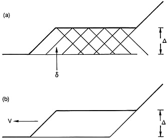
FIGURE 3-1 Two structural models of ship grounding: (a) sequence of re-initiation and (b) steady-state propagation.
be modeled either as a sequence of re-initiations of the idealized dentings, or as a continuing damage process (see Figure 3-1b) with increasing depth, either at the point of collision or at different points along the ship's length in a grounding. This is shown diagrammatically, for groundings, in the idealization of Figure 3-1a. Local force-deformation characteristics of the hull girder, under the indenting force, determine the lateral and longitudinal extent of damage and the length of transition zones between damaged and as-yet-undamaged parts of the hull.
The "interaction" phase is characterized by contact forces in the rigid body motion of the ship and local crushing/rupture modes, which determine the relative magnitudes of ship-motion (mostly lateral and rolling in collisions, mostly vertical in groundings) and the local penetration depth. Light, stiff ships with hull plating resistive to rupture may ride over obstacles in groundings with minimal permanent damage; fully loaded VLCCs of current design are likely to incur damage almost equal to the height of the rock above the vessel's bottom, and with little vertical ship motion. These situations are contrasted in a highly idealized manner in Figures 3-2a and 3-2b.
In groundings, one of the most dangerous failure modes is the rupture of
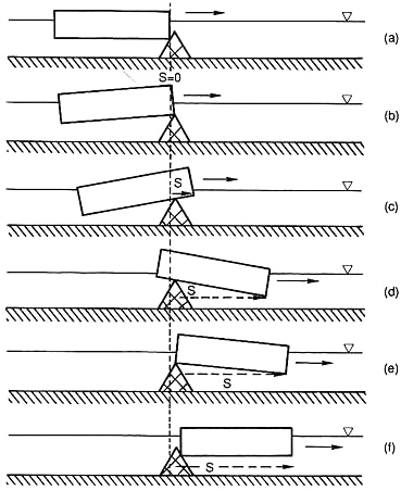
FIGURE 3-2a Idealized ship-rock configuration in a ride-over mode.
plating and the detachment of longitudinal stiffeners from the bottom plating. Both of these modes were observed during the committee's visit to the damaged EXXON VALDEZ. The rupture of plating, the more disastrous of two possible conclusions to the "initiation of local damage" phase, occurs when hull material's strain limit is exceeded. If this happens, and rupture occurs before the full kinetic energy is dissipated, then rupture progresses in the "steady-state" mode. Detachment of stiffeners usually follows; this
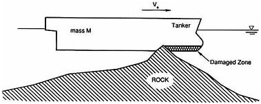
FIGURE 3-2b Idealization of a typical high-energy grounding scenario.
occurs when the shear stress in the welds attaching stiffeners to hull plating exceeds the allowable yield stress of the weld material. A critical penetration depth can be defined as the depth at which material separations occur, as determined by failure in either of the two modes.
The time scale of most collisions is too short to view the process between initiation of local damage, and either the disengagement of the ships or their attainment of equal velocities, as a steady-state mode.
A simple mechanics-of-materials model explaining how the crushing-tearing mechanism dissipates energy (in the failure initiation phase) is shown in Figure 3-3. As the component of indenting force in the plane of the material is resisted in pushing through the distance , energy is dissipated by plastic deformation and failure resulting in the membrane tension gap labeled "G-1." A similar model representing the steady-state bottom tearing process is shown in Figure 3-4. Energy dissipation also occurs in a membrane tension failure, evidenced by the gap labeled "G-2." Smaller amounts of energy are dissipated through the "moving plastic hinge," generated in the plate curling action shown in Figure 3-5.
If the energy absorption of all structural members of the hull girder participating in the damage process are collected, energy dissipation beyond that of bottom friction and weight lifting can be estimated. Examination of the associated forces also can be related to global ship parameters. This method, which represents the dissipative action of specific structural arrangements and scantlings, promises to predict the extent of damage to the hull girder in groundings and collisions (Wierzbicki et al., 1990). An earlier concept related the resisting contact forces between colliding ships only to the volume of distorted materials in the side of a stricken ship (Minorsky, 1959). This approach, which has the advantage of simplicity, "averages out" details of structural arrangements and scantlings, and requires that proportional constraints be determined on an empirical basis. Because struc-
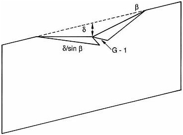
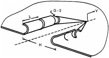
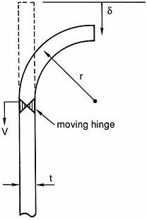
FIGURE 3-5 Progressive out-of-plane bending with a moving plastic "hinge."
tural members are subjected to compressive or crush loading in groundings, like the bow and side structures in a collision, the "volume of distorted material" approach can be extended to cover grounding of ships as well (Vaughan, 1977). This method2 accounts for fracture of bottom plating by modifying the original empirical collision formula, through use of a term related to the area of the hull plating involved. The proportionality constant is determined from experimental data.
From results now available, it appears that the most efficient way to improve energy-absorbing capacity for ships involved in collisions or groundings may be (1) to increase the thickness of shell plating, (2) to employ material with increased capacity to withstand strain, and (3) to provide substructural (internal framing) arrangements that distribute strains as uniformly as possible, and thus delay rupture. This leads to two further conclusions. First, collision protection for a stricken ship with double sides, and grounding protection for a ship with a double bottom, would both be best served by distributing a given amount of double-shell material such that outer skins are as thick as possible and inner skins are as thin as allowable (Jones,
1990). Second, limiting the propagation of disruption through appropriate substructure design would serve to limit oil spillage, by preserving the integrity of tanks not in the immediate vicinity of hull penetration. Methods for predicting the propagation of damage through such structure, however, are neither well developed nor substantiated. Improvements in hull girder design, therefore, will be limited by appropriate developments in predictive analysis.
Residual Strength Following Damage
A ship whose basic structure (i.e., the "hull girder" formed by the deck, bottom, side plating, transverse and longitudinal bulkheads, web frames, and associated stiffeners) has been damaged severely is imperiled by loads that the intact structure could carry easily. Such damage might result from corrosion, fatigue-related structural failure, collision, grounding, explosion, or fire. If there are no basic changes in applied loads, then the determinative phenomena are, at the macro level, new load paths and, at the micro level, stress redistributions. The ability of the damaged structure to carry such unchanged loads can be called "residual strength." Virtually the same finite element analysis techniques used to predict load paths and stress distributions for the original structural design also can be used to estimate the residual strength of the damaged structure, with appropriate accounting for stress concentrators such as sharp cracks associated with the failure.
By focusing solely on achieving reductions in oil spillage, it is possible to conceive of designs that, once damaged, could place the entire vessel, crew, and cargo at unacceptable risk. Applied loads are unlikely to remain the same following such damage. Among other hazards, breached voids may fill with sea water, cargo may drain into void spaces, and, perhaps most foreboding, a grounded vessel may lose supportive buoyant forces if left impaled on a pinnacle by receding tides. In such cases, residual strength must be provided in the face of both redistributed and/or aggravated loadings and damaged structure. Tank vessel redesign with the intent of reducing pollution risk must consider residual strength very carefully. Aside from the potential for loss of life in the circumstances listed above, all of the cargo is likely to be spilled in the event of total vessel loss.
FIRE AND EXPLOSIONS
All hydrocarbon cargoes and their residues involve danger of fire and explosion. Such cargoes include crude oils, home heating oils and diesel fuel, and such products as gasoline, kerosene, and naphtha. The most volatile are, generally, the most dangerous, but virtually all are flammable at
ambient conditions. Oil vapors accumulating in void spaces, or in ullage spaces (the air space above the cargo) in oil cargo tanks, can be highly explosive.
"Heavy end" fuels, such as those used for ship's bunkers, or power plant fuel, generally will not burn at ambient conditions. Such cargoes, having a flash point of at least 60°C, do not have explosive vapors at ambient conditions, and thus are not as hazardous as crudes or clean products. At elevated temperatures, however, these fuels exhibit the same flammability and vaporizing characteristics as crude and light products.
Asphalt is a specialty petroleum product that must be carried at elevated temperatures even to be liquid. It may be the only petroleum product which does not, of itself, pose some hazard of fire or explosion, unless water is present. In that case, because the high temperature of asphalt cargo can turn water quickly into steam (which expands and foams), a hazardous condition quickly arises.
Conditions for Igniting/Sustaining Combustion
For a fire or explosion to occur, three elements must be present concurrently: semi-solid, liquid, or gaseous hydrocarbons; oxygen in specific proportion relative to the hydrocarbons; and an ignition source. If the hydrocarbons are mainly in gaseous form, combustion, when it occurs, will be in the form of an explosion; otherwise, there will be a fire.
Prevention of fires and explosions requires removal of at least one of the three elements. In practice, neither hydrocarbons nor ignition sources can be removed reliably, for the following reasons.
Hydrocarbons always are present during normal operations, of course, because they constitute the tanker's cargo and its engine's fuel. Total removal of hydrocarbons to the extent that combustion cannot be supported is only possible when a ship's tanks are "gas free" to permit "hot work" in a particular tank; this may occur during either voyage or shipyard repairs. Therefore, unless tanks have been certified "gas free" by a marine chemist, it must be assumed that hydrocarbons sufficient to support combustion are present in the cargo tanks.
Ignition sources exist in several forms aboard tankers. Because of the multiplicity of potential sources, the tanker industry has adopted the position that all sources of ignition never will be fully removed from a tanker. Sources identified, often through costly experience, include the following:
-
Static electricity, generated by washing of cargo tanks with water or, most often, crude oil. Sparks of electrical potential sufficient to initiate combustion can be released through potentials generated between the tank washing medium and the surrounding tank walls.
-
Sparks from tank gauging tapes or other instruments, if not properly grounded when lowered into cargo tanks.
-
Magnesium or aluminum sacrificial anodes (placed in cargo tanks to prevent corrosion) can become ignition sources if they drop to a tank bottom. Only zinc sacrificial anodes are now permitted in tankers; zinc does not produce an incendiary spark if it drops on steel from a height.
-
Steel-on-steel contact, as occurs if a steel object drops to the bottom of a tank, or if improper tools are used by a crew in cargo tanks. Wrenches, buckets, shovels, and even personal items such as pocket knives and keys, can be dangerous in this respect. Another possible ignition source is ''working" between steel members in a ship's structure following material failure or collision.
-
External sources, such as lightning, striking a tanker's venting system, or the result of a collision. In the case of fires following a collisions, large quantities of oil almost always are burned.
-
Ship machinery or electrical installations.
Given the inevitable presence of hydrocarbons and ignition sources, oxygen is the element that industry and governments have sought to eliminate during normal operations. This is done by "inerting" cargo tanks—filling the ullage space with gases that do not support combustion. The source of such gases can be either cleaned ("scrubbed") flue gas from the ship's boilers or, as is now common, a separate inert gas generator. The principal ingredients of the cleaned residue (derived from thorough combustion of hydrocarbon and oxygen) are nitrogen (roughly about 80 percent), and carbon dioxide (roughly 12-14 percent).
The incorporation of inert gas systems (IGS) in tankers over 100,000 DWT was mandated by the international SOLAS convention in 1974. This regulation was extended in 1978 to include all new or existing crude oil tankers over 20,000 DWT, and product tankers over 40,000 DWT. 3 This does not apply to barges.
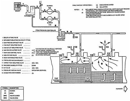
Figure 3-6 shows, schematically, the major components of an IGS (Gray, 1979). Note that an IGS connects cargo tanks, which contain potentially explosive hydrocarbon vapors, to the ship's engine room, with its multiplicity of ignition sources. Cargo tanks are isolated from the ignition sources in the inert gas generator by a non-return valve and a water seal. The effectiveness of an IGS depends on maintaining a positive pressure in the cargo tanks so that oxygen will not enter. Tanks are vented through pressure vacuum valves that open whenever a predetermined pressure or vacuum in the tank is exceeded.
Fires and Explosions Outside of Cargo Tanks
Numerous potential sources of ignition exist in non-cargo spaces, such as the engine room, the ship's quarters, and the galley. In these spaces, just as on other types of ships, the main fire/explosion preventatives are simply good practices around hot machinery; e.g., removing sources of oil leaks,
grease, and other flammables such as dirty rags. Tankers do, however, differ in one important respect from other ships in this regard, as they are fitted with a pump room.
Pump rooms usually are located centrally between the cargo tank block and the ship's stern, just forward of the engine room. The pump room houses the pumps and valves that control operation of the cargo system and ballasting system. The pump drivers, being potential ignition sources, generally are not in the pump room, but in the engine room; they are connected to the pumps by a shaft through a bulkhead. These drivers can be steam turbine, reciprocating steam engine, electric or hydraulic motor, or diesel engine power sources.
In the pump room itself, with its many pipes, valves, and pumps, the main defenses against fire or explosion are rapid ventilation to remove hydrocarbon vapors as soon as they are generated, and appropriate fire extinguishing systems. Because crew members are often in the pump room during cargo handling, an IGS system isn't possible there (the crew could not breathe). On modern tankers, much of the work could be handled from a cargo control room, but there is always a possibility of malfunction or operational difficulty, requiring crew members to enter the pump room. The pump room generally is considered the second most dangerous area in a tanker, next to the cargo tanks.
CORROSION AND FATIGUE
Corrosion of metal occurs through a spontaneous electrochemical mechanism in which a portion of the metal (the anode) is oxidized, and a substance in the environment (the cathode) is reduced. These two aspects of the process, oxidation and reduction, take place at different, though usually not widely separated, areas of the metal, with an electrical current flowing between the two.
If an alternate source of electrical flow is provided, then corrosion can be inhibited. This source can be provided by either active (powered) electrical systems or by passive "sacrificial" material chosen to act as an anode.
Adherent and nonporous films can protect surfaces from corrosive forces by increasing resistance in the path between cathode and anode, and by decreasing diffusion rates of reactants and products of electrode reactions to or from the metal surface. Naturally occurring oxidation films can inhibit further corrosion, if the oxide has (1) a higher specific volume than the metal, (2) forms under compression as a result, and (3) covers the entire surface under attack when the film has grown to only a few molecular layers in thickness. Many substances that act as anions, such as those encountered in seawater and salt-spray, break down oxide film and acceler-
ate corrosion. Mechanical strains that cause cracking, of course, also can deprive films of their protective powers.
Oxygen concentrations in either fresh or sea water droplets can be nonuniform, and this so-called differential aeration causes areas of wet metal surfaces to be anodic where oxygen concentration is low and cathodic where it is high. Since the edges of droplets have good access to oxygen and the centers do not, anodic attack on the metal occurs near the center of droplets, with rust rings building up at the edges. This is among the phenomena leading to "pitting."
Internal stresses due to applied loads, or residual stresses from fabrication processes, generally make metals more anodic and tend to increase the rate of corrosion. Furthermore, once corrosion takes place, stress concentrations are aggravated particularly at points of attack, due to the sharp crack tips that usually occur there combined with the reduced metal thicknesses brought about by corrosion. This is one form of the phenomenon called stress corrosion and is by nature a progressive problem, as such cracks will continue to propagate.
Repeated cycles of stress ultimately cause structural materials to fail (fatigue) at stress levels considerably lower than could be tolerated under static conditions. Many structural materials have a protective endurance limit, an alternating stress level below which the material will not fail, even with an infinite number of applied stress cycles. But in the presence of corrosion, this limit falls precipitously. If corrosion continues long enough, almost any stress level will be sufficient to cause structural failure.
From this limited discussion, it follows that segregated ballast tanks, located between the outer hull and in-board cargo tanks, can be particularly susceptible to corrosion. In pre-MARPOL ships, seawater ballast was placed mostly in tanks that recently had held cargo; the oily film clinging to tank sides provided some measure of corrosion protection. But in a segregated ballast tank, only salt water and air may be held, so any metal plating without a protective coating is subject to a highly corrosive environment. In most new ships, ballast tanks are coated to prevent corrosion. Maintenance of these coatings is an important element in ship management. In all ships, the tank walls are part of the ship's primary structure (the hull girder), and as such are subject to stress, which contributes to deterioration of hull coatings.
In a ballast tank, the outer hull has thicker metal, but is subject to highly corrosive elements on both inner and outer surfaces. Moreover, the outer hull is usually the most highly stressed material in the ship's structure. Inner plating, while usually thinner, has the protection of cargo residue on one or more sides. Still, even very small, corrosion/pitting holes in the inner plating can have the most serious consequences; they can permit hydrocarbon vapors to enter empty ballast spaces, where they pose explosion
hazards. Water-crude oil combinations, which tend to collect on cargo tank bottoms, are particularly troublesome. Resulting corrosion-related phenomena on tank bottoms make tanks susceptible to corrosion from the cargo side as well as the ballast/void side.
Protective coatings often are used to inhibit corrosion. Painted external hulls, of course, are in this category. Because many events can remove paint during normal operation, this protection usually is complemented by active systems, below the water line, which provide a flow of electrons to the cathodic material. For reasons explained previously, this alternate current source serves to inhibit corrosion. Most classification societies require that water ballast tank plating receive protective surface treatment, often complemented by "sacrificial" anodic materials or systems to act as alternate current sources. But such systems only function when the ballast tanks are filled with seawater, and corrosion can proceed when these tanks are empty. Sacrificial anodes, therefore, have limited use, and limited effectiveness.
HYDROSTATIC PRESSURES IN OPPOSITION
When a loaded tanker's hull is breached, seldom does the entire cargo spew into the sea. It can happen, but only in rare cases where the entire ship is lost (such as the ARGO MERCHANT and AMOCO CADIZ, listed in Table 1-3). In groundings, where the bottom of a cargo tank may be breached, usually only part of that tank's cargo is spilled. No cargo escapes, obviously, from cargo tanks that remain intact, or from breached voids, ballast tanks, or empty cargo tanks. The EXXON VALDEZ spill, great as it was, represented only about 20 percent of the total cargo. While an ecological calamity, the fact remains that 80 percent of the cargo was saved. This section seeks to explain how this is possible, by addressing the physical mechanisms governing oil outflow.
Hydrostatic pressure is an isotropic phenomenon. That is, at any given point in a fluid the pressure will be the same, regardless of the direction in which it is measured. The hull plating on a ship can experience a net pressure in or out, depending on the depth of the oil and water at that point. Oil will run out of a submerged tank opening only if the (interior) hydrostatic pressure of the oil at the opening is greater than the (exterior) hydrostatic pressure of the sea at the same point.
The hydrostatic pressure, or "head," of a column of liquid, h, is defined as its height times its specific weight, gρ, where ρ is the mass density of the liquid. When comparing the heads of two columns of different fluids, then, it is convenient to think in terms of their specific gravities, ρ/ρwater, where ρwater is the density of fresh water. The specific gravity of crude oil varies between 0.83-0.90, a common value being 0.86. The specific gravity of sea water is 1.025. The relative heights of columns of oil and sea water in
equilibrium (i.e., having equal pressure) at a given point will be inversely proportional to their specific gravities. Thus, the height of an oil column, relative to that of a seawater column with which it is in equilibrium, can be expressed as:
where sg is specific gravity, h is a consistent measure in feet or meters, and the subscripts o and w represent oil and seawater, respectively. For oil with a sg = .86, and seawater at 1.025, the column height ratio, ho/hw = 1.025/0.86 = 1.192. In other words, the column of oil with a density that produces equal pressure will be 19 percent higher than the balancing height of sea water. This is a significant difference, and it suggests that tankers might adopt loading schemes or install systems that take advantage of these differences in specific gravity, to minimize the potential loss of cargo from groundings.4
The way most tankers are loaded at present, the cargo level establishes a hydrostatic pressure at the tank (and ship's) bottom that is greater than external sea pressure. Thus, if the tank is breached, then cargo flows out. (In fact, the external pressure equals the tank pressure at a point several feet to 15 feet or more below the ship's bottom, depending on cargo density.) But if a tanker carried somewhat less cargo, to establish a hydrostatic balance at or several meters above the tank bottom, water would tend to enter the ship through the hole in the hull (as long as the highest point of damage was below the hydrostatic balance level). The implementation of this concept, hydrostatically balanced loading (or hydrostatic control), is discussed in Chapter 5. Cargoes with specific gravities close to that of water can be expected to form an emulsified interface; this is likely to increase the pollution potential of hydrostatically balanced loading schemes for such cargoes.
If cargo and seawater are in hydrostatic equilibrium at the ship's bottom, then for any distance above that point on the ship's side, the cargo and seawater pressures will be out of balance. Thus, the amount of the height of the oil column that must be lost to reachieve balance, say x, following rupture of the tank's side (as might occur in a collision a distance, y, above the bottom) will be given by x = 0.192y. For specific examples of the effects of hydrostatic pressure on oil cargo, see Figure 3-7.
This discussion of hydrostatic balance assumes equal atmospheric pressures at the surfaces of both seawater and oil cargo. As the latter is enclosed in a tank, it can be subject to other pressures. If there are overpressures, as required currently for IGS, oil outflow would be increased in a tank breach. Conversely, reduced ullage space pressures would reduce oil outflow. This suggests another means of controlling oil outflow in groundings; implementation of this concept is discussed in Chapter 5.
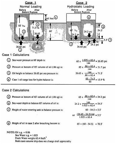
FIGURE 3-7 How hydrostatically balanced loading works.
This figure depicts two tankers, each with a 60 foot draft. Case 1 shows the ship loaded with 85 feet of .86 specific gravity oil in the left tank. The hydrostatic oil pressure at the tank portion is greater than sea pressure. The right hand tank bottom is breached and oil runs out until the hydrostatic pressures are balanced. Note that the height of remaining oil is still above the waterline but that 15.9 percent of the original cargo was lost to the sea. (The example assumes the ship draft did not change significantly.)
In case 2, the ship is only loaded with 65 feet of oil. Breaching the right hand tank results in water entering to a height of 5.5 feet to establish an equilibrium with the oil. No oil escaped. This is equivalent of hydrostatic loading to a level of 5.5 feet inside the ship's bottom.
From case 1, it is shown that hydrostatic loading to the level of the bottom, to minimize cargo outflow, would mean carrying 15.9 percent less cargo than shown in the left hand tank.
There is one more mechanism that can increase oil outflow following a collision, after hydrostatic balance is established. Consider a situation in which some oil remains in a tank, after the balancing process, below the damage to the tank side. A disturbance, such as wave action or ship rolling, may throw seawater into the tank. The heavy water will sink, as it will not float on the lighter oil; the water therefore must displace the oil, which then rises and exits through the hole. This is obviously a much slower process than oil outflow driven by unbalanced hydrostatic pressure. Even without ship or water motion, some exchange of oil and water will occur as the result of differences in specific gravity.
Finally, it should be noted that a few liquid cargoes have specific gravities greater than that of seawater. In such cases, the cargo's lack of buoyancy will override hydrostatic phenomena and result in all cargo above a submerged hole "dropping out" of the opening. The cargo will be replaced by seawater to the level of the waterline. Consequently, the advantages associated with hydrostatic control scheme are applicable only to vessels carrying cargoes of specific gravity significantly less than water. This excludes vessels carrying, for example, feed stocks, caustic soda, or asphalt.
DIFFUSION AND DYNAMICS OF FLUID/VESSEL MOTION
When no membrane, such as hull plating, separates two fluids, such as oil and seawater, there will be some mixing at the surfaces where the fluids are in contact. The degree of mixing depends on the particular situation.
Consider the typical series of events when a cargo tank is breached at its bottom. If the oil has a hydrostatic head exceeding that of the seawater at the point of damage, then the oil escapes relatively quickly, especially if the tank opening is large. In fact, for the larger holes, oil outflow may be limited by the rate at which the ship's cargo venting system allows air to enter the expanding void space above the surface of the oil. For a large hole, it may take as little as two or three minutes to lose 20 percent of the cargo. Because most of this will be lost almost immediately, there is obviously insufficient time to take steps to repair the hull, even temporarily, to prevent this escape.
Once hydrostatic equilibrium is established at the opening, smaller amounts of oil can continue to escape as the tide falls (if the ship is aground) or as the ship rolls and pitches because of wave action. In this context, tide-related actions are measured in hours, offering time for use of on-board cargo transfer systems (discussed in Chapter 5). While such losses are driven in part by hydrostatic variations, over a longer time there is likely to be some mixing of oil and water inside the cargo tank due to hydrodynamic effects, such as turbulence in the oil and/or water. In high-energy collisions or groundings, violent mixing of oil and water can occur at the outset,
creating a fluid with a specific gravity that lies between those of the oil and seawater. This may result in some oil outflow beyond that associated with simple hydrostatic effects.
When ullage space is sufficiently large, cargo sloshing can be a problem. If either or both the ship's rolling and pitching frequencies approach the natural frequencies of the fluid in partially filled cargo tanks, then higher wave forces than exist with smaller ullage spaces could develop within the tanks. Such forces are capable of damaging internal bulkheads.
SUMMARY
From the preceding pages, it is clear that tank vessel designers and operators must be aware of a variety of complex and interrelated physical phenomena. The topics highlighted in this chapter are of particular relevance in this study, as they become important factors in assessment of design alternatives intended to reduce the risk of pollution resulting from casualties.
Several findings can be drawn from the brief discussion of the physical basis of the damage process occurring in collisions and groundings, fire and explosion hazards, corrosion, hydrostatic pressure, and dynamics of fluid/vessel motion. These findings are as follows.
In considering the damage protection afforded by double bottoms, double sides, and double hulls, protection appears to be greatest when outer hull is as thick as possible, even at the possible expense of the inner skin. Beyond such guidelines for conventional hull structures, there appears to be great potential for diminishing the extent of hull damage, and even preventing the initiation of plate rupture in higher energy groundings and collisions, through proper selection of external hull materials and/or innovative structural design.
Hydrostatic balance can be achieved at some point along the hull of a cargo tank—at the bottom, for example—and this can reduce or eliminate oil outflow. Reduced pressure in ullage spaces can achieve hydrostatic balance with greater oil cargo depths. But long-term buoyancy naturally drives all oil from below a side hull opening beneath the waterline.
Corrosion, metal fatigue, and the threat of fire and explosion require fastidious and continuous attention, because of both their potentially disastrous consequences and the difficulty of prevention.
With this theoretical discussion as a prelude, the following chapter will discuss engineering considerations related to tank vessel casualties.
NOTES
|
2. |
The committee's pollution-control analysis of alternative tank vessel designs, conducted by Det norske Veritas and detailed in Chapter 5, was based on this methodology. |
|
3. |
Also covers existing product tankers having high-capacity washing machines for cleaning tanks. |
|
4. |
In actual practice, these calculations would be adjusted to account for inert gas pressure, if present. |
REFERENCES
Gray, W.O. 1979. Requirements for Inert Gas Systems. Paper presented at IMCO Tokyo Seminar on Tanker Safety and Pollution Prevention, February 19-23, 1979.
Jones, N. 1990. Some Comments on the Collision Protection of Ships with Double Hulls. Paper presented at meeting of the Committee on Tank Vessel Design, Washington, D.C., June 5-7, 1990.
Lloyd's Register of Shipping. 1990. Statistical Study of Outflow from Oil and Chemical Tanker Casualties. Report conducted for the American Petroleum Institute, Washington, D.C. Technical Report STD R2-0590.
Minorsky, V.U. 1959. An Analysis of Ship Collisions with Reference to Protection of Nuclear Power Plants. Journal of Ship Research 3:1-4.
Vaughan, H. 1977. Damage to Ships Due to Collision and Grounding. Paper published by Det norske Veritas, Oslo, Norway, August 1977. DnV 77-345.
Wierzbicki, T., E. Rady, and J.G. Shin. 1990. Damage Estimates in High Energy Grounding of Ships. Paper presented at meeting of the Committee on Tank Vessel Design, Washington, D.C., June 6-7, 1990.


