


Below is the uncorrected machine-read text of this chapter, intended to provide our own search engines and external engines with highly rich, chapter-representative searchable text of each book. Because it is UNCORRECTED material, please consider the following text as a useful but insufficient proxy for the authoritative book pages.
Earthquake Input EARTHQUAKE EXCITATION CONCEPTS In evaluating the earthquake performance of concrete dams, it is evident that descriptions of the earthquake ground motions and the manner in which these motions excite dynamic response are of paramount importance. The procedure that leads to the selection of the seismic input for concrete dams is similar, in general, to that for other large important structures such as nuclear power plants and long-span bridges. It involves the study of the regional geologic setting, the history of seismic activity in the area, the geologic structure along the path from source to site, and the local geotechnical conditions. Ground motion parameters that may be utilized in characterizing earthquake motions include peak acceleration (or effective peak acceleration), duration, and frequency content of the accelerogram. However, the methods of selecting such seismic parameters for the purpose of generating input ground motions or response spectra are well documented (2-1) and are not repeated here. The focus of this chapter is on the specification of earthquake input motions to be used in the analysis of concrete dam-reservoir-foundation systems. Obviously, the level of sophistication to be used in defining the seismic input is closely related to the degree of understanding of the dynamic behavior of the dam system and to capabilities for modeling such behavior. Thus, progress in defining seismic input has followed a long evolutionary process parallel to that of the dynamic analysis capability. It is not surprising, therefore, that the earliest method of defining earthquake input to concrete dams was merely to apply a distributed horizontal force amounting to a uniform specified fraction (typically 10 percent) of the weight of the dam body. This force was intended to represent the inertial resistance of a rigid 16
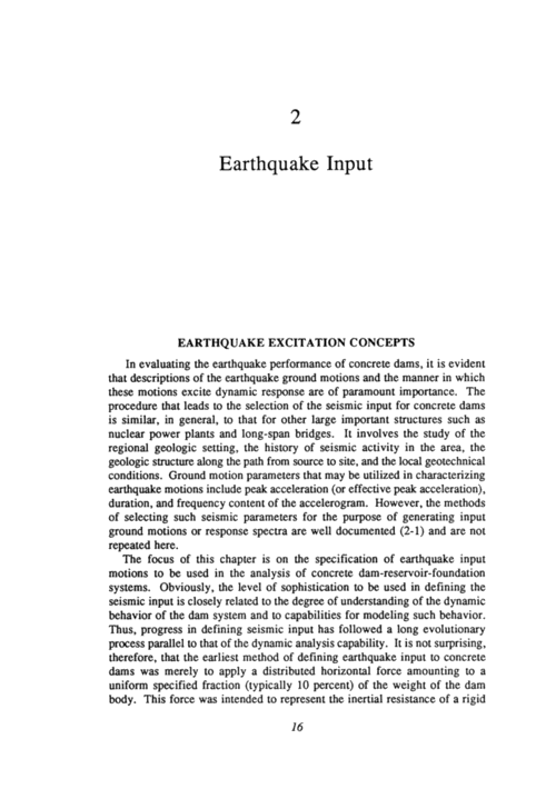
17 dam subjected to the horizontal motion of a rigid foundation. The procedure was easily extended in an approximate sense to include the hydrodynamic pressure effects of the reservoir water by invoking the added mass concept (i.e., assuming that a portion of the reservoir water would move together with the dam body). Major improvements over the rigid dam approach resulted when the dynamic effects of dam deformability, i.e., the free vibration behavior, were recognized. The first improvement was to convert the equivalent static force from a uniform distribution to a form related to the dam fundamental vibration mode shape. The second improvement was to account for the amplification of the base input motions in the response of the dam. Representing these frequency-dependent amplification effects by means of the earthquake response spectrum provided an appropriate amplitude of equivalent static load distribution to be used in the response analysis. The basic assumption of all these methods of analysis is that the foundation rock supporting the dam is rigid, so the specified earthquake motions are applied uniformly over the entire dam-foundation interface. However, as the methods of response analysis improved, it became apparent that the rigid base earthquake input no longer was appropriate. Because of the great extent of the dam, and recognizing the wave propagation mechanisms by which earthquake motions are propagated through the foundation rock, it is important to account for spatial variation of the earthquake motions at the dam-foundation interface; these spatial variations also may result from "scattering" of the propagating earthquake waves by the topography near the dam site. A brief discussion of basic procedures for defining seismic input is presented in a recent report (2-2~; the essential concepts contained in that report are summarized in the following paragraphs. Standard Base Input Model The dam is assumed to be supported by a large region of deformable rock, which in turn is supported by a rigid base boundary, as shown in Figure 2-la. The seismic input is defined as a history of motion of this rigid base, but it is important to note that the motions at this depth in the foundation rock are not the same as the free-field motions recorded at ground surface. Massless Foundation Rock Model An improved version of the preceding model is obtained by neglecting the mass of the rock in the deformable foundation region. This has the effect of eliminating wave propagation mechanisms in the deformable rock, so that motions prescribed at the rigid base are transmitted directly to the
18 ,~ CANYON WALL ~ DEFORMABLE FOUNDATION ROCK __ _~ ~ ~ ~ ~ / ~ ~ ~ ~ ~ ~ / ~ ~ ~ / ~ ~ / ~ ~ A RIGID BASE ~ Vgz ( t ) SEISM IC INPUT ~~ ~V9x ( t ) Vgy(t) FREE FIELD MOTION (MEASURED BY HORIZONTALLY L AYERE D FOUNDATION ROCK RIGID BASE MOTION (CALCULATED BY DECONVOLUTION ) - ?'MED SUPPORTED APPROPRI ATE LY FOR EACH EARTHQUAKE CO M PO N E N T ~\\~",' / i: CANYON _' WALL DEFO RMA B L E FOU NDATI O N ROC K DECONVOLVED RIGID BASE MOTION LIMIT OF FLEXIBLE WON i._. ~ 1 At' ~ \ \: ~ CANYON INPUT AT CAM I~TF~FArF /~/~/ L' FIGURE 2-1 Proposed seismic input models for concrete dams (2-2). (a) Standard rigid base input model; mass of foundation rock either included or neglected. (b) Deconvolution of free- field surface motions to determine rigid base motions. (c) Analysis of two-dimensional free- field canyon motions using deconvolved rigid base motions as input. (d) Analysis of three- dimensional dam-foundation system response using two-dimensional free-field canyon motions as input.
19 dam interface. With this assumption it is reasonable to prescribe recorded free-field surface motions as the rigid base input. Deconvolution Base Rock Input Model In this approach, as illustrated in Figure 2-lb, a deconvolution analysis is performed on a horizontally uniform layer of deformable rock to determine motions at the rigid base boundary that are consistent with the recorded free-field surface motions. The resulting rigid base motion is then used in the standard base input model. This procedure tends to be computationally expensive because the mathematical model includes a large volume of foundation rock in addition to the concrete dam. Free-Field Input Model A variation of the preceding procedure is to apply the deconvolved rigid base motion to a model of the deformable foundation rock without the dam in place, in order to determine the free-field motions at the interface positions where the dam is to be located. These calculated interface free-field motions account for the scattering effects of the canyon topography on the earthquake waves and are used as input to the combined dam-foundation rock system. In many cases of the form shown in Figure Alec), it may be reasonable to assume two-dimensional behavior in modeling the scattering effects and then to apply these two-dimensional free-field motions as input to a three- dimensional dam-canyon system, as indicated by Figure 2-l~d). In the above-mentioned report (2-2) these seismic input models are discussed in the context of arch dam analysis, but they are equally applicable for gravity dams when the foundation topography warrants a three-dimensional analysis. If the dam is relatively long and uniform, so that its response may be considered to be two-dimensional, the canyon scattering effect need not be considered, but the seismic input still may vary spatially due to traveling- wave effects. It is important to note that all four of the input models listed above include a rigid boundary at the base of the deformable foundation rock; thus, vibration energy is not permitted to radiate from the model. Elimination of this constraint is one of the key issues in present research on seismic input procedures. Of these four input models the free-field model usually is the most reasonable, so a key element in the input definition is the determination of appropriate free-field motions. Research progress in this area is discussed in the next section.
20 PRESENT STATUS OF KNOWLEDGE Prediction of Free-Field Motion Definition of seismic input is very closely related to the way the dam- reservoir-foundation system is modeled. Although existing finite element programs for the dynamic analysis of concrete dams (2-3, 2-4, 2-5) use uniform base motion as input, these programs can be modified to accept nonuniform earthquake excitation at the interface between dam and canyon wall. In this case the free-field motion is defined as the motion of the dam- foundation contact surface due to seismic excitation without the presence of the dam. Two-Dimensional Case Method If the canyon where the dam is to be located has an essentially constant cross section for some distance upstream and downstream, it may be treated as a linearly elastic half-plane, and the problem of evaluating the earthquake free-field motion can be formulated as a wave-scattering problem with the canyon as the scatterer. Various approaches have been used to obtain solutions to the problem. The case involving earthquake SH waves (i.e., horizontal shear waves) is somewhat simpler in the sense that only out-of-plane displacements occur. Closed-form solutions have been obtained for semicircular canyons (2-6) and for semielliptical canyons (2-7~. For cases with more general geometry, further assumptions must be made in the formulation or He numerical solution techniques. By using the method of images and integral equation formulation, results have been obtained for SH wave scattering due to arbitrarily shaped canyons by solving the integral equation numerically (2-8~. The same problem also has been solved using a different integral equation formulation (2-9~; in this approach the free boundary condition at the canyon wall is satisfied in the least squares sense. An integral equation approach that imposes an approximately satisfied boundary condition also has been used in the solution of problems involving P and SV waves (2-10) (i.e., compression and vertical shear waves). Similar procedures have been used by others in solving P. SV, and Rayleigh wave problems (2-11, 2-12~. A solution for incident SH, P. and SV waves also has been obtained by assuming periodicity in the surface topography and a downward-only scattered wave (2-13~. Direct numerical solution using a finite difference formulation has been employed to evaluate the scattering effects of various surface irregularities- for example, a ridge with incident SH wave (2-14), vertically incident SV and P waves on a step change in surface (2-15), and the use of nonreflecting boundary conditions with other surface irregularities (2-16~.
21 Direct finite element solutions also have been used to solve scattering problems of P and SV waves incident on a mountain and on an alluvium- filled canyon (2-17), using more than one solution to obtain the canceling effect on nonreflecting boundaries (2-18~. Standard plane-strain soil dynamics finite element programs with special treatment at nonreflecting boundaries (2-19, 2-20, 2-21) reportedly have been used for P. SV, and SH waves with a simple modification (2-221. A particle model combined with finite element modeling to account for an irregular surface has been used for SV waves incident to cliff topography (2-23~. The free-field motions at V-shaped and close-to-V-shaped canyons also have been studied using a combination of finite and infinite elements in a model with finite depth that extends to infinity horizontally (2-24~. In this case earthquake motions prescribed at the rigid base of the foundation are taken as input to the system. Two-Dimensional Case Results Results for a semicircular canyon are used as the basis of discussion here because the most information is available for this simple geometry; some reference also is made to cases involving other geometries, as depicted in Figure 2-2. Results expressed in the frequency domain are described in many cases to indicate the effects of wave frequency. Motions at the canyon walls generally are found to be dependent on the ratio of canyon width to wave length (wave frequency), on the angle of wave incidence, and on the wave type. The effect of scattering is more significant when the wave length is of the same order as or smaller than the canyon width. In comparison with the free-field motion without any canyon, the free-field motion at the canyon surface can be either amplified or reduced depending on the location of the observation point, as shown in Figure 2-3. In general, motions near the upper corner of the canyon facing the incident wave are amplified; the amplification increases as the wave length decreases and as the direction of incidence tends toward the horizontal. For incident SH, P. SV, and Rayleigh waves, the maximum amplification is found to be 2 for semicircular and semielliptical canyons (2-6, 2-7, 2-121. However, this amplification factor can be higher if the canyon surface has local convex regions, which tend to trap energy (2-~. Motion from SH and Rayleigh waves generally is reduced near the bottom of the canyon. For Rayleigh waves and close-to-horizontally incident SH waves, the motion at the back side of the canyon also is often reduced, but this shielding effect disappears for SV and P waves. For vertically incident SH waves, the wall slope of a triangular canyon has significant effects on the motion at the wall surface (2-9~; steeper slopes lead to greater reductions in motion near the bottom of the canyon. The amplification of motion at some locations and the attenuation of motion at others results in a large frequency-dependent spatial variation of
22 SH, P. SV, RAYLEIGH - SH - - - - \ SH, P. SV, RAYLEIGH / \ ~ 1 SH, P. SV FIGURE 2-2 Valley shapes and input wave types for which two-dimensional analyses of wave- scattenng effects have been reported. motion along the canyon walls. This spatial variation is more abrupt when the canyon-width-to-wave-length ratio is larger than 1 (higher frequency) for all types of waves. Calculated relative motion ratios of 2 to 3 are common in many cases of differing incident angles and wave types. For the more irregular geometry of a real canyon, a calculated relative motion ratio as high as 6 was reported for Pacoima Dam, California (2-~. The relative phase of motions along the canyon walls has been reported for the case of SH waves incident to a semicircular canyon (2-6~. It seems that the phase variation is close to what can be predicted from simple traveling- wave considerations for most of the canyon wall. Near the upper corners of the canyon, however, more abrupt variations of phase angle appear. From the above brief description of theoretical results, it is clear that the spatial variation of free-field motion is very complex and frequency dependent. In an effort to obtain an averaged index of motion intensity, a Topographical Effects Index was defined using the Arias Intensity Concept (2-25~; however, this index is still dependent on location and angle of incidence. Three-Dimensional Case Analytical solutions for three-dimensional canyon topography are much more difficult to obtain. For the simple case of a hemispherical cavity at the surface of an elastic half-space, series solutions have been obtained for
23 5 C] 4 - ~ 3 id LL ~ 2 LL a: CO 1 4: 3 2 1 o 1 2 3 6 7 8 7= 30 . - - ~ mar \4 5/ SH / / ;~ 0~ 0 1 2 3 5 1 2 3 6 7 8 ' ' 1 ~ I- ' ' SH \4 5J \/ ~ ~ =60 _ A 1 ~ 0 1 2 3 FIGURE 2-3 Calculated amplification of incident plane SH waves by a semicylindrical canyon surface (2-6). A flat free-field surface gives a displacement amplitude of 2; ~ represents the SH wave velocity.
24 incident P and S waves (2-26~. A boundary element method that satisfies the free surface condition at and near the canyon walls in a least squares sense has also been applied to axisymmetric cavity problems (2-27), although results are given only for a hemispherical cavity with a vertically incident P wave. Perhaps the most relevant solution for three-dimensional canyon topography is that obtained by finite element analysis of Pacoima Dam and its adjacent canyon (2-28), shown in Figure 2-4. Part of the foundation rock was included with the finite element model of the dam, taking account of the variations in the rock properties. Three-dimensional modeling was considered necessary because of the complex topography, which is apparent near the dam, consisting of a thin, spiny ridge at the left abutment and a broad, massive right abutment. A rigid base motion was assumed at the finite element base boundary, and its three components of motion were calculated by a process of deconvolution from the three components of earthquake motion recorded on the ridge above the left abutment. The strong-motion accelerograph was located at the crest of the ridge, as indicated in the photograph. The peak acceleration of the filtered left abutment record was 1.15 g, and that of the calculated base motion was 0.40 g. This result indicates that the amplification may be larger than expected because of the assumed rigid energy-trapping boundary at the base; also, the assumption of uniform motion at the base may have contributed to the conservative results. Applicability of the Results The theoretical free-field motion results have limitations in their application due to the various simplifying assumptions made in their derivation. In the two-dimensional analyses it was assumed that the change of topography along the upstream-downstream direction was negligible; therefore, the results are valid only for prismatically shaped canyons. Moreover, the results apply only to specific wave types, and the amplification effect of wave scattering is very much dependent on the type of incident wave. Unless the composition of an actual incident earthquake wave is known in terms of its wave types, such results are not directly applicable. Often a complicated canyon geometry requires that free-field motion varying in three dimensions be considered, and it is doubtful that any method other than a numerical one can be expected to produce realistic results for such cases. Even with a numerical approach the various assumptions made in treating the finite boundary and in modeling the inhomogeneous media may introduce errors; thus, both two- and three-dimensional results need to be compared with actual free-field earthquake records to assess their applicability (2-29~. 7 ' Because of the many uncertainties involved in modeling the geometry,
25 FIGURE 2-4 Pacoima Dam, California, was subjected to the 1971 San Femando earthquake; the seismic motions were recorded by a seismograph on the narrow rock ridge above the left abutment, at the point indicated (2-28).) (Courtesy of George W. Housner) the foundation material properties, and the incident earthquake motion, it is probable that a stochastic approach to defining the free-field motions will be needed in addition to the deterministic procedures reviewed in this report. Random field theory (2-30, 2-31) is quite relevant to the problem of spatial variation of earthquake input motion. Using the stochastic approach, some work already has been done for free-field motions over a flat, open surface (2-32, 2-33, 2-34, 2-35~. To date, no results have been reported on the probabilistic nature of seismic motions along a canyon wall.
26 Measured Motions of Foundation Rock Reports of actual earthquake motion recorded at the walls of a canyon are very scarce; however, the importance of differential input motion at a dam site is well recognized, and a few such reports do exist, mostly for abutment motion of existing dams. As early as 1964, differential motion at the two abutments of the Tonoyama (arch) Dam in Japan was reported (2- 36, 2-37~. The dam is 65 m high, with a cross-canyon width at the crest level of about 150 m. The maximum recorded acceleration at the center of the dam crest during an earthquake in 1960 was 0.018 g, and those at the two abutments were less than 0.010 g. In general, the records at the two abutments appeared to be quite similar in magnitude and phase. However, Fourier analysis revealed that the amplitude of motion at the right abutment was two to three times that at the left abutment for frequencies greater than 4 [Iz. Other observations made in Japan at the Tagokura (gravity) Dam (2- 38) and at the Kurobe (arch) Dam (2-39) also indicate differing motions at the opposite abutments; however, in both of these cases there was amplification of motion over the height of the abutments. Eight aftershock measurements were made in the vicinity of Pacoima Dam after the San Fernando earthquake (2-40~. Comparison of the records obtained at the south abutment near the original strong-motion station with those obtained at a downstream canyon floor location some distance from the dam revealed an average amplification of about 1.5 for horizontal motions at the top of the ridge. The amplification was about 4.2 near a frequency of 5 Hz but decreased to a ratio near 1 for lower frequencies. In a separate study four aftershocks of the San Fernando earthquake were recorded at two stations, one near the dam base and the other near the top of Kagel Mountain (2-41~. The two stations were approximately 3,000 ft apart and were selected to represent the free-field motions at the base and top of the mountain. The highest time-domain horizontal acceleration ratio (top-to-base) was about 1.75, but the frequency-domain ratio, as measured by the pseudorelative velocity spectra, was as high as 30 at a frequency of about 2 Hz. A correlation study on ground motion intensity and site elevation was carried out for the general area of Kagel Mountain and Pacoima Dam using the San Fernando earthquake data (242~. On a larger scale it was found that there was an almost linear relationship between the peak recorded motion of a site and the recorder elevation, as the profile rises from the lower San Fernando dam site (approximately 1,200 ft) to the Pacoima dam site (approximately 2,000 It) to the peak of Kagel Mountain (approximately 3,500 ft). Based on this linear relationship, it was calculated that the base rock acceleration at the Pacoima dam site was about 0.99 g, but it is evident that this calculation ignores local topographic features such as the abutment ridge. In a somewhat similar case, aftershocks of the 1976 Friuli earthquake in
27 Italy were measured at the Ambiesta (arch) Dam (2-43~. The dam is 60 m high, and the canyon width at the crest level is about 140 m. Records were obtained at three locations along the dam-foundation interface, two at crest level at the abutment and one at the base of the dam. The average ratio of horizontal peak velocity at the crest level to that at the base of the dam ranged from 3.11 to 1.88. The predominant frequency of motion at the base of the dam was about 4 Hz, based on more than 35 records having peak velocities greater than 0.002 cm/sec. Observed motion at the Chirkey (arch) Dam in the Soviet Union was reported in a translated paper (2-44~. The motion at the left abutment was recorded at three heights during a magnitude 3.5 earthquake that occurred on 4 February 1971 at an epicentral distance of 46 km. The peak velocities at heights of 160, 220, and 265 m were 0.4, 0.63, and 0.62 cm/see, respectively. In the frequency domain it was found that the maximum spectral value increased by a factor of 2.5 when the height of the observation point increased by 100 m. The Whittier, California, earthquake of 1 October 1987 triggered all 16 of the accelerometers that had been installed on Pacoima Dam. Preliminary reports indicated that the accelerations at the dam base were on the order of 0.001 g, while those at about 80 percent height of the dam on the dam- abutment interface were on the order of 0.002 g (2-45~. All of the above-mentioned records were of small amplitude due to low- intensity shaking. A larger-amplitude record was obtained at the Techi dam site in Taiwan during an earthquake on 15 November 1986 (2-46~. This arch dam is 180 m high, and the canyon width is about 250 m at crest level. The peak acceleration recorded at the center of the crest in the upstream- downstream direction was 0.170 g. Three strong-motion accelerographs had been installed along the dam-foundation interface, one at the base of the dam and the others at about midheight on the opposite abutments. Unfortunately, one of the midheight instruments malfunctioned, leaving only one operational. The peak acceleration obtained at the dam base in the upstream-downstream direction was 0.014 g, while that at midheight of the dam-abutment interface was 0.022 g. In the cross-canyon direction the peak acceleration at the dam base was 0.012 g, versus 0.017 g at the midheight abutment location. These records clearly demonstrate a large spatial variation of motion along the foundation interface, but it is probable that dam interaction contributed significantly to the recorded motion. Consequently, these data are not representative of free-field canyon wall motions. A 1984 earthquake of amplitude comparable to the Techi event was reported recently for the Nagawado (arch) Dam in Japan (247, 2-48~. The dam is 155 m high with a crest length of 355.5 m. The peak recorded radial accelerations of the dam crest were 0.197 g at midspan and 0.245 g at the quarter point from the left abutment. The recorded peak accelerations in
28 the foundation rock 17 m below the base of the dam were 0.016 g in the N- S direction and 0.029 g in the E-W direction; the dam axis lies approximately in the N-S direction. At a level about 25 m above the base of the dam, an accelerograph installed deep in the right abutment rock away from the dam recorded accelerations of 0.018 g (N-S) and 0.021 g (E-W). Almost directly above this accelerograph, also deep in the right abutment, an instrument at crest level recorded peak accelerations of 0.031 g (N-S) and 0.026 g (E-W). Across the canyon at crest level deep in the left abutment, another recorder indicated peak accelerations of 0.026 g (N-S) and 0.021 g (E-W). The spatial variation revealed by these data is quite indicative of the lack of uniformity in the earthquake motions of the rock supporting the dam. In a translated paper (2-49) the findings of a model test of Toktogul Dam are reported. The model had a length scale of 1:4,000 and it simulated the topography of the Toktogul dam site, which covers an area of 6 x 6 km and was 4 km deep. The model was subjected to excitation initiated at different points on the model, and the motion along the canyon wall was recorded up to a height from the bottom of the canyon equal to twice that of the dam. Three configurations were tested: without the dam, with the dam but without water, and with both dam and water; generally the greatest motion occurred for the empty canyon case. More recently model test results were reported for an existing arch dam and for a proposed arch dam, both in China (2-50~. The model scales were 1:600 and 1:2,000, respectively, and input to the models was both random excitation and impact. The model test results were found to be consistent with those from finite element analyses and from ambient vibration surveys. An amplification factor of between 2 and 3 was observed for abutment motion at the crest level relative to motion at the bottom of the canyon. Predicted Response to Spatially Varying Input Dynamic Excitation Direct application of measured earthquake motions to predict dam response has been reported for the Ambiesta (arch) Dam (2-51~. Three records are available, one at the base of the dam and two at the crest level near opposite dam-abutment interfaces. In the analysis the interface was divided into three zones by drawing a horizontal line near midheight on an elevation view of the downstream face. Within each zone a uniform boundary motion identical to what was recorded in that zone was used as interface input. It was reported that agreement between the calculated accelerations along the crest of the dam and the corresponding measured quantities was startlingly good, while poor agreement resulted if uniform input motion was used along the entire interface.
29 Using prescribed input motions at the foundation rock boundary, the effects of differential input motion on the responses of a gravity dam and an arch dam have been studied by finite element analysis (2-52~. A two- dimensional plane-strain analysis was performed of the gravity dam and its supporting block of foundation rock, assuming a traveling-wave input along the horizontal foundation base boundary. To reduce the amount of computation, the boundary was divided into four regions, with uniform motion assumed in each. The dam was 46 m high, and the length of the horizontal base boundary was approximately twice the height of the dam. The input wave form was that of the S16E component of the 1971 San Fernando earthquake recorded at Pacoima Dam, and three wave speeds were used: 2,000 m/see, 4,000 m/see, and infinite. Stress analysis results indicated that as the wave speed was reduced the stresses in the dam increased. In the case of the 110-m-high arch dam, which had a crest length of 528 m, a three-dimensional analysis was performed. The left half of the foundation boundary was assumed to move uniformly according to the prescribed San Fernando earthquake record, while the right half was held fixed. It was reported that different stress patterns in the dam were obtained for the variable base input as compared with the uniform base input. In a recent study on traveling-wave effects, a small portion of the foundation rock was treated as an extension of the dam body, and shell equations were used to model the extended arch dam (2-53~. Cross-canyon traveling waves in the form of harmonic motion or earthquake motion were then assigned to the periphery of the shell; reservoir effects were neglected. Results indicated that stresses in the dam increased when the period of the input harmonic wave approached the fundamental period of the shell. In a separate study the effects of traveling waves on arch dams were examined using a finite element approach (2-54~. The model was similar to the free-field input model described above, but the free-field motion was taken as a prescribed traveling earthquake wave. It was found that the effects of a wave traveling in the upstream direction were not significant when compared with the rigid base input. However, a traveling wave in the cross-canyon direction caused an average stress increase of 40 to 50 percent and a doubling of the maximum computed stress. Traveling-wave effects also have been studied, with emphasis on the energy input to the reservoir water. A two-dimensional solution was reported for the problem of a rigid gravity dam with infinite reservoir excited by a vertical traveling ground motion (2-55~. Three cases were studied: infinite wave speed, wave leaving the dam moving upstream, and wave approaching the dam from upstream. The vertical component of the E1 Centro 1940 earthquake was used, and in the latter two cases the wave propagation speed was taken to be three times the speed of sound in water. It was found that maximum pressure on the dam occurred when the wave approached from
30 upstream, and it was lowest when the wave propagated away from the dam. In terms of maximum total force or overturning moment, the larger traveling- wave response was almost twice that resulting from the infinite wave speed. A similar conclusion, but with much less difference between the cases for infinite and finite wave speeds, was obtained by a finite difference study of a flexible-dam finite-reservoir model (2-56~. Later a finite difference solution scheme was applied to an improved model that included energy-transmitting boundaries and elastic foundation (2-57~. It was reported, however, that traveling waves did not produce more critical stress conditions in the gravity dam than did the wave with infinite propagation speed. Applications of an energy-transmitting boundary approach to a free-field input model were reported recently (2-58~. A numerical example was given to illustrate the computation procedure for a uniform free-field input motion assumed along the dam-foundation interface. In another study a new input procedure that included the influence of the infinite foundation domain was developed (2-59~. The analysis procedure was divided into two stages: first, the stresses were computed on a fictitious fixed boundary facing the incident wave; these stresses were then released in the second stage, when the complete domain was modeled by finite elements near the canyon and by infinite elements away from the canyon. Numerical results were obtained for a three-dimensional dam topography, considering an SH wave propagating across the canyon. The displacement amplitudes at the crest and on the crown cantilever were found to be much reduced from those obtained using a uniform base input. The presence of the dam body was found to have the general effect of reducing the motion at the canyon wall, as compared with the free-field values at the same locations. A recent study (2-60) of an arch dam used free-field motions for the seismic input that were computed for a canyon embedded in a two-dimensional half space and subjected to incident SH, SV, and P waves. These free-field motions were applied to a three-dimensional finite element model containing the dam, a massless foundation region, and an infinite reservoir of compressible water. Frequency-domain responses were converted into the time domain in the form of standard deviations of the response to a random input with an earthquakelike frequency content. As shown by an analysis of Pacoima Dam, inclusion of nonuniformity in the stream component of the excitation reduces the dam response, while the effect of nonuniformity in the cross- stream and vertical components varies, with the potential for some increase. For various cases of nonuniform input, the average arch stress along the crest ranged from 62 to 122 percent of that for uniform input.
31 Fault Displacement All the above-mentioned analyses were for vibratory seismic input motions. The case of a fault-displacement offset occurring directly beneath the base of a concrete gravity dam also has been studied. In a two-dimensional nonlinear analysis of a dam-foundation system (2-61), a reverse fault was simulated by applying concentrated forces along an assumed fault zone that extended from the finite element boundary of the modeled foundation rock to the base of the dam body. Results for the particular case studied indicated that the dam did not crack as a result of fault displacement but partially separated from the foundation. It was recommended that the combined effect of fault displacement and vibratory seismic input could be accounted for in preliminary studies by performing a dynamic-response analysis with a linear finite element model, using a softened foundation. More recently a model test study of a proposed 185-m-high arch dam in Greece was carried out to determine the effects of fault displacements occurring directly beneath the base of the dam (2-62~. Selection of the dam type and location was based on economic considerations. A thorough seismotectonic investigation concluded that fault displacement at the dam base of as much as several decimeters could not be ruled out; consequently, design measures were taken to accommodate such possible movement. Among these was a sophisticated joint system to alleviate the adverse effects of the fault displace- ment. A 1:250 scale model was built and tested at the Laboratorio Nacional de Engenharia Civil (LNEC) in Lisbon. The horizontal movement of the fault was simulated by imparting to the left abutment a gradual displacement upstream to compress the arch. Results of the test indicated that the joint system worked very well in protecting the dam from collapse for a displacement of up to 1 m in prototype scale. It was also concluded that the joint system would enable the dam body to withstand a fault displacement of the order of 5 to 10 cm without damage. There have been two cases where concrete gravity dams have actually been constructed in which the plane of an underlying fault has been extended through the entire dam section in the form of a sliding joint to accommodate possible fault movement (2-63~. These are Morris Dam (2-64) in California, which was completed in 1934, and the recently finished Clyde Dam (2-65) in New Zealand. In both cases the fault ran along the river channel perpendicular to the axis of the dam and dipped about 60 degrees off horizontal. Figure 2- 5 is a photograph of Morris Dam. The joint is located near the gallery entrance, which can be seen on the downstream face. The sliding joints in both dams were oriented vertically and were designed for displacements on the order of 2 m. This required an interesting geometric solution, details of which were quite different in the two cases. To date, no movement has occurred on either fault.
33 Other methods of defensive design of concrete gravity dams for fault displacement include the placement of a zoned self-healing berm of embankment material at the heel of the dam and a buttressing berm of free-draining granular fill against the downstream face (2-63~. Reference 2-63 also states that an acceptable defense may not exist for thin arch dams against fault displacements. STATUS OF STRONG-MOTION INSTRUMENT NETWORKS The topic of strong-motion instrumentation placed at concrete dam sites for the purpose of studying the spatial variation of ground motion has not received sufficient attention. Traditionally, for recording the input motion it was considered adequate to have one strong-motion recorder at either the toe of the darn or one of the abutments. As early as 1975, however, it was recommended that there be a minimum of two accelerographs located at the dam site to `'record earthquake motions in the foundation" (2-66, p. 1,099~. The purpose of requiring two instruments was "to give some indication of the uniformity of conditions, and to ensure some useful information in the event of an instrument malfunction." In the 1978 International Workshop on Strong-Motion Instrument Arrays, various aspects of instrumentation were discussed, and useful suggestions were made specifically for study of the spatial variation of seismic ground motions (2-67~. One of the array types suggested was the "local effect array" that could be used to study the "variation of ground motions across valleys." But in that suggestion the emphasis was clearly on the motion of the overburden soil in a valley rather than that along a canyon wall. In a follow-up meeting of U.S. researchers in 1981 (2-68, p. 8), the following recommendation was made: "Lifeline and other systems should be instrumented along with building structures. These should include highway bridges and overpasses, dams, and other utility system facilities. The degree of instrumentation should be sufficient to obtain information equivalent to that for building structures." However, few if any concrete dams in the United States are currently instrumented to the extent needed to study the seismic input problem. Of the 45 concrete dams listed in a survey report (2-69), only Pacoima Dam has strong-motion instruments installed at both the toe and two abutments (as well as at other locations on the dam). Although the survey list is not complete, very few other concrete dams have seismographs installed near the toe. Even though the measuring of free-field and interface input motion has been recognized to be as important as that of the dam response (2-70), current strong-motion instrumentation for concrete dams in the United States is inadequate for the purpose of defining seismic input.
34 RESEARCH NEEDS Various theoretical models have been developed for prediction of free- field motion at the surface of a valley or canyon to be used as input to a dam system; however, no verification of such input predictions has yet been achieved by comparison with actually recorded earthquake motions. The existing strong-motion instrumentation at concrete dams is not designed to provide such essential data. It is clear, therefore, that an improved instrumenta- tion program for observation of earthquake motions at sites of existing or proposed dams is needed. Similarly, further theoretical work is needed on the deterministic and stochastic modeling of input motion to provide the basis for realistically modeling seismic input to concrete dams. Specific recommendations for research on earthquake input to concrete dams follow: 1. Deployment of Strong-Motion Instrumentation (a) Arrays of strong-motion instruments should be deployed at selected dam sites. The locations of the instruments at each site should include at least three elevations along the abutment interfaces and selected locations within the abutment rock, the face of the canyon downstream of the dam, and several positions along the reservoir bottom. Triggering of these instruments should be synchronized so that traveling-wave effects can be detected. The seismographs should be made part of an overall instrumentation system that includes pressure transducers at the dam surface in the reservoir and accelerographs at selected locations within and on the dam body. (b) An array of strong-motion instruments should be deployed at sites being considered for construction of concrete dams to obtain the free-field motions at a canyon location without the interference of an existing dam. 2. Strong-Motion Instrumentation Program . (a) The necessity of obtaining actual records and the high cost of instrumentation point to the need for a concerted joint effort between the dam owner/operator and the research community. A permanent or semiperma- nent instrumentation program should be established after a careful study of potential sites for instrumentation. (b) A joint program of strong-motion instrumentation for concrete dams In areas of high seismicity should be developed in cooperation with other countries having similar hazards. 3. Use of Recorded Seismic Motion Records Seismic motions actually recorded at a dam-foundation interface should be utilized in analyses intended to verify the various input methods. Because
35 the recorded motions would be affected by dam-foundation interaction, a system identification approach may be needed to determine the free-field input motion. 4. Enhancement of Two-Dimensional Analyses Currently available two-dimensional theoretical free-field canyon or valley wall motions are presented in terms of the incident wave angle and wave type and are in a frequency-dependent form. Even though they are of limited applicability because of assumptions regarding two~imensional geometry and homogeneity of the medium, these results should be synthesized to provide guidelines for defining realistic input for concrete dams. 5. Enhancement of Three-Dimensional Models The deterministic prediction of free-field motion at a dam site with three- dimensional topography can be performed by numerical methods such as finite elements, boundary elements, finite differences, or some combination of the three. The development of nonreflective boundaries for such three- dimensional models remains a high-priority requirement. 6. Stochastic Approach In view of the many uncertainties involved, the simulation of spatially varying free-field motion may require the application of stochastic theory; therefore, methods should be developed for simulating stochastic inputs for valley and canyon topographies. 7. Effects of Fault Displacement Further studies should be carried out focusing on the effects of fault displacements on the safety of concrete dams, using both numerical simulation procedures and physical model testing. The effectiveness of joint systems in a dam at the location of the fault break should be included in these studies.
