APPENDIX B
CASE STUDY OF A COMPOSITE AIRFRAME STRUCTURE
A composite horizontal stabilizer was chosen as the subject for the composite airframe structure case study. Life-cycle engineering was examined in today's environment from conceptual design through production and into operational feedback phases. The subject stabilizer was a composite-skinned structure with a metal splice plate over honeycomb core.
The same procedure was used for a future idealized environment. The subject stabilizer for the future study was a totally co-cured composite structure without metal splice plates. By comparing the present and future or proposed methodologies for life-cycle engineering, needs for each phase of product development (conceptual design, prototype, full-scale development, production, and operation) were isolated. These needs were then compared to needs identified by the committee and the resulting critical issues in order to verify or refute them. The case study of the composite horizontal stabilizer that follows includes today's environment, an idealized future environment, and the resulting needs.
The contemporary structure studied was an F-15 horizontal stabilizer (Figure B-1) designed in the 1970s using methodologies and practices consistent with the technologies and tools available. The design process has changed very little since then, and a similar design process would be followed today. The conceptual design was developed by design, material and processes, strength, weights, aerodynamics, and loads engineers with inputs as required from other manufacturing and engineering disciplines.
The stabilizer design was completed and forwarded to individual experts for review of the design concepts as they relate to areas such as producibility, reliability, maintainability, and repairability. Individual input from each of these areas would be forwarded to design engineering for incorporation in the design.
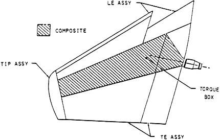
Figure B-1 Plan view of the F-15 horizontal stabilizer.
The materials for the composite horizontal stabilizer were assessed for material properties and history (Figure B-2). Costs shown were budgetary and based on divisional estimates for engineering study purposes.
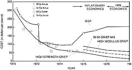
Figure B-2 Material properties and history assessment.
Source: 1970–1975 procurement actuals; 1975–1980 vendor quotations.
The assembly method selected was a bonded honeycomb torque box overlaid with graphite-epoxy laminated skins and a removable, mechanically attached aluminum leading edge and trailing edge section. As noted in sections A and B in Figure B-3, conventional fastening methods were used—i.e., bolts and nut plates.

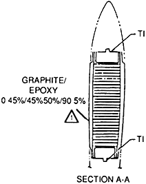
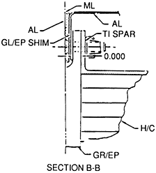
Figure B-3 Torque box assembly method.
Tooling employed was state of the art for the 1970s and was based on experience and past history on aluminum honeycomb assemblies, with consideration for cost and schedule constraints was then factored in.
Prototyping, if done at all, was accomplished as a feasibility validation through the use of a physical development fixture approach. This is a labor-intensive activity that generally yields a low level of fidelity. The physical development fixture is reviewed during various stages of completion by numerous "experts." Paper feedback of problems from engineering, manufacturing, quality assurance, and product support are sent to design engineering for consideration of design changes for a completed design.
During full-scale development, additional problems are found as the integration of structure and systems occurs. This may lead to delays as interface problems are discovered, and assembly and/or tooling procedures may require modification. Inspection changes may also be required, and basic engineering changes to the design are also common at this time. Most of these changes are in the form of "paper feedback" and affect a number of different areas of the plant.
In summary, the contemporary method of life cycle engineering is paper dependent. It is not structured or organized to prevent numerous reoccurrences of the same problems. It lacks
feedback loops for some data altogether; and, over product quality, reliability, and supportability suffer as a result.
The next task of this case study was to probe the future and determine those things that would be necessary in an idealized future environment to best support life cycle engineering, and its attendant improvement in total product quality.
In this idealized future environment, during the development phase of a horizontal stabilizer the conceptual design will be developed digitally by design, material and processes, strength, weights, aerodynamics, and loads engineers with electronic or digital inputs from producibility, reliability, maintainability. Inputs from rules imbedded in the digital system will be available, such as a mature reliability and maintainability in computer-aided design (RAMCAD) system, presently under development. Additionally artificial intelligence (AI) systems will incorporate reliability, maintainability, and supportability such as export systems for access door design, equipment mounting, crew system safety, scheduling etc.
Also, in the future environment the "ilities" will carry as much weight with customer and contractor as performance. For example, an "ilities" warranty will be required, and ''ilities" requirements will be spelled out in the same detail as performance. (An extension of warranties increasingly used in the current environment.)
The best design practices for composite structural members will be imbedded in the digital CAD-CAM-CAL-CAQA system. The system will contain parameters on failure modes, damage tolerance, typical repairs, wear-out characteristics, predicted moisture effects, and tooling concepts. An integrated data base for engineering, manufacturing, quality assurance, and product support will be required. This will allow data to be shared rather than duplicated or lost altogether (Figure B-4).
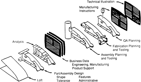
Figure B-4 Shared data base concept.
This shared data base concept will minimize data stored, maintain attachment to data originator for updates (change notification), maintain attachment to data originator to propose changes to better fit downstream users needs (change proposals), and allow status change notification (shared, prerelease, release). It will also provide a means to organize "lessons-learned" data from related current and prior programs.
Prototyping will be done electronically with more analytical assurance of component performance before committing to hardware fabrication. It would establish relationships, assess integration and provide tools for anthropometric and ergonomic analyses.
Electronic integration of systems and structures will include an electronic development fixture (EDF) to minimize changes and find errors before parts are made and assembled. Electronic development fixtures will reduce cost, reduce span time, and provide more accuracy than the previous hardware development fixture method. Electronic development fixtures will allow the aircraft to be divided up into zones, with engineers from many disciplines responsible for all activities within the individual zones. This will provide for better coordination of all systems and structures in a given zone, foster coordination and increase knowledge transfer. The use of a full-scale electronic development fixture will also permit a fine-tuning of the design to take advantage of the efficiencies of volume production in areas like pressings and forgings.
The use of a common electronic data base by the whole design team (Figure B-5) will provide many new approaches for users of the engineering design definition, such as electronic quality assurance of parts prior to fabrication and assembly. Other downstream users of engineering digital definitions will allow for the automated processing of composite parts. For example, the manufacturing planning function will document models of processes, plan automated fabrication and assembly operations, use the computer mock-up EDF instead of a hard metal airframe, and release detail designs in digital data set formats. This will lead to earlier isolation of problem areas for correction in detail and assembly processes, prior to full scale production via the common electronic data base.
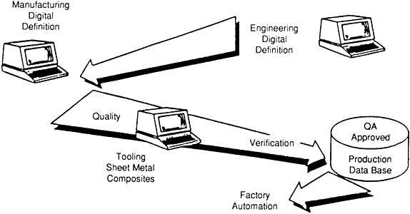
Figure B-5 Application of common electronic data base.
Shared information will be the common thread that will enhance quality and lower cost. An integrated data base for data flow in all directions is a method of achieving life-cycle engineering goals.
Shared information will also be the common thread in automated facilities for composite detail and co-cured parts plus subassembly and final assembly. Examples are the Integrated Composites Center (ICC), Automated Airframe Assembly Center (AAAC), Automated Machines Center and Cells, and Automated Sheet Metal Center and Cells now under development.
Shared information will be the common thread for totally integrated experience information storage and transfer to a central system (integrated data base) that controls need-to-know access.
Finally, shared information will be the common thread for an intelligent system that recognizes and flags recurring problems for upstream correction by use of imbedded rules, artificial intelligence systems, integrated data base for information flow, available computerized inspection data concerning initial part quality, and availability to user of analytical computer models, for overload, damage and repair support.
Having examined the present design environment and gazed into our crystal ball for a look at the idealized future environment, a set of unified life cycle engineering (ULCE) needs and concerns will be isolated for review and comparison with the critical issues identified by the committee.
ULCE needs and concerns for the horizontal stabilizer used in this case study are listed under headings according to the various product development phases:
Conceptual Design
-
Construct a complete experience-oriented analytical and operational expert system data base for the design engineer that includes all the human expert input on composite horizontal stabilizer and canard structure that is used today, including repairs.
-
Develop lightweight, low cost tooling for composite structure, including detail tools (hard and soft) and assembly tools (emphasizing co-cured opportunities).
-
Develop thermoplastic composites to improve repairability and reduce scrap.
-
Develop methods to embed reliability, maintainability, and supportability rules into generic CAD, CAM, CAL, and CAQA systems.
-
Develop an automated inspection system.
-
Embed analysis tools into CAD, CAM, and CAL systems for all downstream users to avoid delays for fixes and repairs.
-
Develop expanded digital capabilities necessary to maximize CAD, CAM, CAL, and CAQA impact on design, including color; large display (both quality and quantity of data) for reviews and for integration applications; solids modeling; interactive hardware library; interactive symbol library; features; and ability to handle nongeometric data (tolerances, finish, material and process information, notes, and effectivness).
-
Share data via an integrated (common electronic) data base with downstream users for their inputs as early in the design cycle as feasible.
Prototype
-
Develop and validate accurate models and simulation routines.
-
Develop expanded digital capabilities necessary to maximize impact of an EDF, including color, large display, solids modeling, and interactive hardware library.
-
Use integrated data base to flag areas of concern for further effort during full-scale development.
-
Use integrated data base to flag areas of opportunity during full-scale development, including robotics applications, numeric control and hybrid numeric control applications, concurring to reduce parts and fasteners, injection molding parts to minimize weight, reduce cost, and minimize galvanic corrosion, and forging, pressing, and casting applications.
Full-Scale Development
-
Develop artificial intelligence systems that can relate specific mission requirements to system and component histories and access the applicable portions of the integrated data base.
-
Develop artificial intelligence systems that can recognize and flag problems for corrective action.
-
Develop models of composite fabrication processes for automated processing.
Production
-
Institute factories of the future concept through completion and expansion of USAF programs to develop integrated centers for composites, machining, sheet metal, and assemblies.
-
Provide for interactive response to manufacturing problems to minimize delays and repairs.
-
Educate all users of the integrated data base in using its two-way flow of information.
Operation
-
Implement routines for complete operational monitoring and feedback to the integrated data base.
-
Develop artificial intelligence systems that can recognize and flag recurring nonconformance records for correction where applicable via the integrated data base.
Having examined the present, gazed into the future and attempted to isolate needs and concerns, the single remaining task is to correlate the case study needs and concerns to the critical issues as identified by the committee.
Critical Issue 1: ULCE-driven development of materials processing and repair methodologies requires integration of R&D across disciplines.
Supporting Case Study Needs and Concerns: 1, 2, 3, 5, 6, 12, 14, 15, 19, 20
Critical Issue 2: Advanced analytical modeling and simulation methods to predict actual component manufacture, operation, and logistics do not exist to the degree required to preclude the need for physical prototypes and mock-ups.
Supporting Case Study Needs and Concerns: 5, 9, 10, 15
Critical Issue 3: The information system for an integrated team approach to ULCE is inadequate.
Supporting Case Study Needs and Concerns: 8, 12, 13, 17, 19
Critical Issue 4: The ULCE team will need to make key decisions while still operating with incomplete information.
Supporting Case Study Needs and Concerns: None.


