
The Car and the Cloud
Automotive Architectures for 2020
RAHUL MANGHARAM
University of Pennsylvania
Over the past two decades, automobile journey durations have doubled. Furthermore, travelers increasingly use their vehicle as a mobile office, meeting room, and even living room. With this evolution, informational and entertainment needs in the vehicle now transcend mechanical, electronic, and software boundaries to include services for the driver, passengers, and the vehicle itself.
Three trends are emerging in drivers’ expectations for their vehicle: (1) continuous connectivity with both the infrastructure (e.g., smart traffic intersections) and other commuters, (2) enhanced levels of productivity and entertainment for the duration of travel, and (3) reduction in cognitive load through semiautonomous operation and automated congestion-aware route planning. To address these demands, vehicles should become more programmable so that almost every aspect of engine control, cabin comfort, connectivity, navigation, and safety will be remotely upgradable and designed to evolve over the lifetime of the vehicle.
Progress toward the vehicle of the future will entail new approaches in the design and sustainability of vehicles so that they are connected to networked traffic systems and are programmable over the course of their lifetime. To that end, our automotive research team at the University of Pennsylvania is developing an in-vehicle programmable system, AutoPlug, an automotive architecture for remote diagnostics, testing, and code updates for dispatch from a datacenter to vehicle electronic controller units. For connected vehicles, we are implementing a networked vehicle platform, GrooveNet, that allows communication between real and simulated vehicles to evaluate the feasibility and application of vehicle-to-vehicle (V2V) and vehicle-to-infrastructure (V2I) communication; the focus in this paper is on its application to safety. Finally, we are working on a tool for large-scale traffic congestion analysis, AutoMatrix, capable of simulating more than 16 million
vehicles on any US street map and computing real-time fastest paths for a large subset of vehicles. The tools and platforms described here are free and open source from the author.
PROGRAMMABLE VEHICLES
Vehicles today are built in long design cycles and with electronic architectures that are static in both form and function. Technology adoption is considered only at the beginning of the design cycle, frozen for the lifetime of ownership of the vehicle (~12 years1), and often obsolete within 6 years.2,3 In contrast, the vehicle of the future will be programmable with services for the long-term health and performance of both humans and vehicles.
Electronics and software for engine and cabin controls currently account for over 30% of the cost of an automobile, and this figure is expected to grow as vehicles evolve from mechanical to electronic to software-controlled to service-based mobile cyber-physical system (CPS) platforms. As new automotive electronic architectures are developed to enable remote diagnosis and reprogrammability throughout the life of the vehicle, drivers will be able to choose from a software component marketplace to enhance the safety, performance, and comfort of their vehicle.
Ensuring the safe and correct programming of the new service features is paramount. Automotive plug-and-play devices that communicate to and from the vehicle will allow new classes of services and customization such as online vehicle diagnostics, warranty management, networked infotainment, and integration of applications such as driver behavior and vehicle performance measurements for personalized insurance services.
CONNECTED VEHICLES
Every year, approximately 6.4 million car accidents occur in the United States, typically involving three people (two drivers and one passenger). That translates to roughly 19.2 million Americans injured in car accidents each year, or odds of 1:16 for every individual. Several sources4 estimate that over 90% of vehicle crashes are due to driver negligence and therefore avoidable (Duri′c and Miladinov-Mikov 2008).
__________
1Polk.com. 2012. Average age of vehicles reaches record high, January 17. Available online at http://goo.gl/TN5Ow.
2US DOE Office of Energy Efficiency and Renewable Energy, Vehicle Technologies Program. 2010. Average Length of Light Vehicle Ownership, May 10. Available online at www1.eere.energy.gov/vehiclesandfuels/facts/2010_fotw622.html.
3Polk.com. 2012. Americans are keeping new vehicles an average of nearly six years, February 22. Available online at http://goo.gl/7R3N3.
4See, for example, The Economist. Look, no hands: Automotive technology: Driverless cars promise to reduce road accidents, ease congestion and revolutionise transport, September 1. Available online at www.economist.com/node/21560989.
A vehicle’s “safety bubble” is currently limited to its physical body, with integrated crash and proximity sensors (e.g., ultrasonic, LiDAR, radar). In the vehicle of the future, V2V and V2I wireless communication is expected to enhance safety. Such communication technology, when interfaced with the vehicle’s powertrain and using audio and haptic feedback, will be able to issue safety alerts to all approaching vehicles during events such as sudden braking, loss of traction, or airbag deployment. Early warning messages communicated down the highway in a timely “multi-hop” manner (i.e., from one vehicle to another in a few hundred milliseconds) will allow for longer reaction and stopping time and thus prevent a pile-up.
Connected vehicle architectures for such safety-critical automotive systems require much work to ensure security and privacy together with the timely delivery of traffic alerts, warnings, and information updates.
NETWORKED TRAFFIC SYSTEMS
Delays due to traffic congestion cost Americans $78 billion in the form of 4.2 billion lost hours and 2.9 billion gallons of wasted fuel, and 35–55% of these delays are caused by point-based traffic incidents rather than recurring congestion. As the density of vehicles increases, there is a need for large-scale traffic congestion management such that real-time “eco-routing” can be provided to prevent, avoid, and alleviate traffic back-ups. Models and tools for nationwide traffic congestion management, with networked streaming vehicle data, are required to compute the fastest and most eco-friendly routes without new infrastructure costs.
In the Real-Time Systems Lab at Penn, we are investigating the design of such a platform to enable the scaling of traffic network operations to handle data processing for millions of vehicles, estimate and predict congestion, and facilitate route assignment as well as to model traffic operations and disaster response during congestion.
IN-VEHICLE SYSTEMS: REMOTE DIAGNOSTICS,
TESTING, AND REPROGRAMMING
More than 20.3 million vehicles were recalled in 2010, many because of software issues related to electronic systems such as cruise control, antilock braking, traction control, and stability control. New and scalable methods are necessary to evaluate such controls in a realistic and open setting.
The increasing complexity of software in automotive systems has resulted in the rise of firmware-related vehicle recalls due to undetected bugs and software faults.5 In 2009, Volvo recalled 17,614 vehicles because of a software error in the engine-cooling fan control module that could result in engine failure and possibly
__________
5IEEE Spectrum. 2011. Honda recalls 936,000 more vehicles for electrical and software fixes, September 7. Available online at http://spectrum.ieee.org.
lead to a crash (NHTSA 2009). In August 2011, Jaguar recalled 17,678 vehicles because of concerns that the cruise control might not respond to normal inputs and once engaged could not be switched off.6 In November 2011, Honda recalled 2.5 million vehicles to update the software that controls its automatic transmissions.7
Current automotive systems lack a systematic approach and infrastructure to support postmarket runtime diagnostics for control software (although at least one online source indicates that there is a significant effort to incorporate automotive software testing and verification at the design stage8). Once a vehicle leaves the dealership lot, its performance and operation safety are a “black box” to the manufacturers and the original equipment providers.
Furthermore, for the more than 100 million lines of code and 60-plus electronic controller units (ECUs) in a vehicle (Schäuffele and Zurawka 2005), there are only about eight standard diagnostic trouble codes (DTCs) for software and they are extremely general (e.g., “memory corruption”). Of the DTCs for software, none targets the ECU software even though systems such as stability, cruise, and traction control are critical for safety.
In-Vehicle Diagnostics and Recall Management
The current approach to vehicle recalls is reactive: the manufacturer recalls all vehicles of a particular year/make/model only after a problem occurs in a significant number of them. For a software-related recall, the vehicle is taken to a service center and a technician either manually replaces the ECU that has the faulty code or reprograms the ECU code with the new version provided by the manufacturer.
The wait-and-see approach to recalls has a significant cost in both time and money and may have a negative impact on the vehicle manufacturer’s reputation. Furthermore, the current recall method relies on word of mouth or the transmission of manually logged information from the service centers to the manufacturer, which takes time—during which a safety-critical system may malfunction.
Consequently, there is an urgent need for systematic postmarket in-vehicle diagnostics for control system software so that issues can be detected early. An in-vehicle system would log sensor values and perform runtime evaluation of the states of the system controls. A remote diagnostic center (RDC) would receive the data (over a network link) to prepare a fault detection and isolation response (Figure 1), in the form of a proposed dynamic diagnostic trouble code (DyDTC) that “observes” the ECUs and system control tasks in question. Once sufficient data are captured, the RDC, using a gray-box model of the vehicle (i.e., with
__________
6IEEE Spectrum. 2011. Jaguar software issue may cause cruise control to stay on, October 25. Available online at http://spectrum.ieee.org.
7Reuters. 2011. Honda recalls 2.5 million vehicles on software issue, August 25. Available online at www.reuters.com.
8AUTOSAR (Automotive Open System Architecture); www.autosar.org.
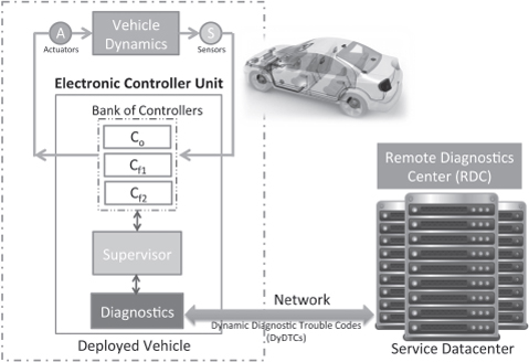
FIGURE 1 Remote diagnostics of automotive control systems showing the vehicle’s software architecture (in dashed box) and the remote diagnostics center (RDC) communicating over a network link. The RDC communicates via the onboard “supervisor” with the vehicle control system to observe its state and update its software in the event of an unexpected fault. C0, Cf1, Cf2 = software-based controllers in the vehicle (e.g., for stability, traction, antilock braking, and cruise control). Using dynamic diagnostic trouble codes (DyDTCs), the RDC observes the state of the vehicle software for postmarket analysis of unanticipated faults.
sensor and control system observation logs), executes system identification to build a model of the vehicle. It then develops a fault-tolerant controller to address the problem and the vehicle is remotely reprogrammed by a code update.
We have developed an early design of such a system, AutoPlug, although we recognize that the approach will be difficult in practice because it would require extensive runtime verification of the updated controller.
Overview of AutoPlug
AutoPlug is an automotive ECU architecture between the vehicle and an RDC to diagnose, test, update, and verify control software. Within the vehicle, we evaluate observer-based runtime diagnostic schemes and introduce a framework for remote management of vehicle recalls. The diagnostic scheme deals with both
real-and non-real-time faults, with a decision function to detect and isolate system faults with modeling uncertainties.
We also evaluate the applicability of “opportunistic diagnostics,” where the observer-based diagnostics are scheduled in the ECU’s real-time operating system (RTOS) only when there is slack available in the system (i.e., it can work with existing hardware in vehicles without interfering with current task sets). The performance of this aperiodic diagnostic scheme is similar to that of the standard, periodic scheme under reasonable assumptions. The framework integrates in-vehicle and remote diagnostics and makes vehicle warranty management more cost-effective.
The aim of the AutoPlug architecture, illustrated in Figure 2, is to make the vehicle recall process less reactive with a runtime system for diagnosis of automotive control systems and software. Our focus is on the online analysis of the control system and control software both in the vehicle ECU network and between the vehicle and the RDC. We assume the network link between the two is available.
The runtime system within the vehicle manages:
• Fault detection and isolation. Sensor, actuator, and control system states are logged for the specific ECU. The data are analyzed locally, and a summary of the states is transmitted to the RDC.
• Fault-tolerant controllers. Once a fault is detected, the high-controller is automatically replaced with a backup controller.
• ECU reprogramming for remote code updates. Upon receipt of reformulated controller code from the RDC (which will guarantee the stability and safety of the vehicle), the runtime system reprograms the particular controller task(s) with the updated code. This can be done over a cellular or wireless communication link.
• Patched controller runtime verification. The updated code is monitored with continuous checks for safety and performance.
While the onboard system provides state updates of the specific controller, the RDC provides complementary support through:
• Data analysis and fault localization. By observing sensor and control system operations locally, structured system identification is used to create a model of the vehicle and its control system is evaluated to isolate faulty behavior.
• Reformulation of control and diagnostic code. A new controller is formulated for the specific vehicle model and further diagnostic code dispatched.
• Recall management. Reformulated controller code is transmitted to the vehicle.
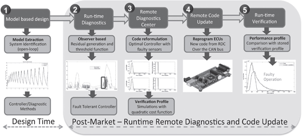
FIGURE 2 End-to-end stages of the AutoPlug automotive architecture. (1) When an unexpected fault is reported, the remote diagnostic center (RDC) sends custom diagnostic code to the vehicle to observe its performance. Using vehicle models developed during the design phase, the RDC safely observes the operation of the software on the vehicle while it is running. Using this information it extracts a new model for the vehicle (perhaps with changes due to wear and tear, faulty sensors, changes in suspension). (2-3) With the updated vehicle model, the control system design is reformulated to correct the faults in the vehicle. (4-5) The RDC remotely updates and verifies the correctness and safety of the reformulated control software. CAN = controller area network; ECU = electronic controller unit.
• Generation of controller verification profiles. The updated controller is probed for performance and safety.
The remote diagnostic system is capable of diagnosing and reformulating controllers with real-time faults (e.g., delay, jitter, incorrect sampling rates) and system faults (e.g., stuck-at faults, calibration faults, and noise in sensors/ actuators).
AutoPlug Testbed
To design and validate the proposed architecture we developed the AutoPlug testbed, which consists of a hardware-in-loop simulation platform for ECU development and testing (Figure 3). The hardware is in the form of a network of ECUs, interfaced by a controller area network (CAN) bus, on which we implement the control and diagnostic algorithms. Each ECU runs a nano-RK RTOS, a resource kernel (RK) with preemptive priority-based real-time scheduling.
Instead of a real vehicle, we use an open-source racecar simulator, which provides high-fidelity physics-based vehicle models and different road terrains, thus affording both the realism of an actual vehicle and the flexibility to implement our own code. In addition, we can introduce faults not covered by standard DTCs. We have tested basic control algorithms, running as real-time tasks on nano-RK, for antilock braking systems (ABS), traction control, cruise control, and stability control to see that the testbed does indeed perform as a real vehicle would.
The main contributions of our applied research and development are threefold:
• an architecture that uses both in-vehicle and remote diagnostics for remote recall management of deployed vehicles;
• modification of the traditional observer-based fault detection and isolation scheme for in-vehicle opportunistic diagnosis, as well as an experimental thresholding scheme in the presence of modeling uncertainties; and
• implementation and evaluation of these schemes on real ECUs for hardware-in-loop simulation.
These three features facilitate postmarket diagnostics, testing, and reconfiguration from a remote data center.
VEHICLE-TO-VEHICLE/INFRASTRUCTURE NETWORKING FOR ENHANCED SAFETY
Connected vehicles involve a special class of wireless networks where the maximum relative speeds are in excess of 80 meters per second, the node density can span more than 9,000 vehicles/mi2, and, most importantly, the dynamics of
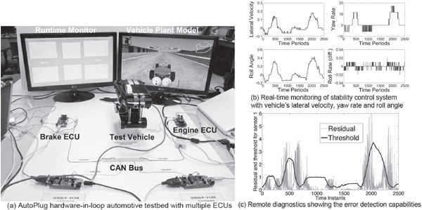
FIGURE 3 (a) AutoPlug hardware-in-loop testbed with real-time monitoring and diagnostics. CAN = controller area network; ECU = electronic controller unit. (b) Real-time monitors for stability controller showing the sensor information of the vehicle dynamics. (c) Analysis of the error signal (i.e., residual) of a particular sensor and its expected values. A smart thresholding scheme is used at the remote diagnostics center to determine the extent of the fault based on the residual signal.
the vehicle, the environment, driver reaction, and interaction with other vehicles are considered in every communication and control decision. Vehicles enabled with programmable short-range wireless networking can communicate with each other and with the infrastructure to enhance the driver’s perception of oncoming danger within hundreds of milliseconds and, within seconds or minutes, route the vehicle based on real-time traffic congestion.
With connected vehicles, it is necessary to analyze and validate the effect of incremental deployment of V2V technologies on message delay, coverage, and persistence in the region of interest. Because it is expensive to develop and test experimental protocols on a large fleet of vehicles, there is a need for vehicular network simulators that faithfully model first-order effects of the street topology, vehicle congestion, speed limits, communication channels, and spatiotemporal trends in traffic intensity on the performance and reliability of V2V networking. Once protocols are designed and evaluated through simulation, their performance must be tested with real vehicles and realistic traffic densities. Although it may be possible to deploy a small fleet of vehicles (e.g., a dozen), it is not yet possible to assess the scalability of such protocols in rush-hour bumper-to-bumper vehicle densities.
GrooveNet Connected Vehicle Virtualization Platform
We have developed the GrooveNet vehicular network virtualization platform to simulate thousands of vehicles on any street map and communicate between real and simulated vehicles. GrooveNet supports a variety of models, network and vehicular system interfaces, message types, and operating modes and, by using the same protocols, algorithms, and software implementation in both real and virtual vehicles, facilitates model-based design, model validation, graceful deployment, and rapid prototyping. It works as both a simulator and in-vehicle network platform with connections to the CAN bus and radios using the recently standardized dedicated worldwide spectrum for vehicular communications (IEEE 802.11p/WAVE standard), a GPS unit, and a cellular interface.
Our tests of GrooveNet with a fleet of five vehicles over 400 miles across urban, rural, and suburban terrain show that it has realistic models for car following, communication, mobility, driver types, traffic lights, road-side communication nodes (e.g., wireless stations that transmit updates about traffic lights to enable drivers to adjust their speed accordingly), and other interactive features of real-time driving. Each GrooveNet-enabled vehicle is capable of tight time synchronization via the GPS pulse-per-second signal for time-critical multi-hop communication. Using this platform we will develop a suite of V2V and V2I safety communication protocols to relay traffic incident alerts and warnings of unsafe road conditions in the Philadelphia and Pittsburgh areas.
Simulated and Actual Use of GrooveNet
Figure 4 shows three real vehicles (in the circles), which I refer to here as R1, R2, and R3 (from left to right). The first two vehicles are within communication range; R3, over a mile away, is not. Thus if a safety alert is triggered by an airbag deployment in R1, only R2 receives the message. To illustrate the progression of the message to approaching vehicles, we simulate virtual vehicles on the same road, each of which will enable a “hop” for the data transmission. R2 sends the message over a cellular link to the vehicle operations director, which simulates the progression of the message from one to another of the virtual vehicles (V1, V2,…) until another real vehicle is in the vicinity of the virtual vehicles. The message thus travels across multiple hops to be received by R3 over the cellular link as if it were from R1. We mask the cellular link’s latency by speeding up the simulated communication across the virtual vehicles.
All vehicles follow the same rebroadcast policy, observe the posted speed limit, and obey car following standards. Vehicle density can be increased arbitrarily and its effects observed by a driver in a real vehicle on the road. Varying the number of virtual vehicles enables us to study the performance of the protocols and network algorithms under various densities, driving conditions, and street topologies. As more experimental vehicles become available, we can increase the realism and validation of our models. In the meantime, network virtualization provides the best of both model-based design and real-world validation with rapid prototyping, with only a few real vehicles needed to operate as mobile gateways.
Figure 5 presents a screen shot of GrooveNet implemented in Linux. In the top left panel is the list of simulated and real vehicles with their current position, street speed, and heading (i.e., direction). The top right panel provides a visualization of the current position and heading of vehicles in Pittsburgh, Pennsylvania. Small circles designate vehicles; circles around a dark arrow represent vehicles that rebroadcast an alert message. The bottom panel shows network connectivity between real vehicles via a wireless communication using the 802.11p/WAVE radio interface and between real and virtual vehicles over the cellular network. For this test we drove five real vehicles along Forbes Avenue in Pittsburgh and conducted experiments with more than 4,000 virtual vehicles.
Such hybrid simulation provides application users with an intuitive feel of the impact of communicating vehicle density on packet delivery ratio and event response time, and provides the developer with feedback about accuracy and details needed in the simulation models. This network virtualization will make it possible to answer questions such as: Under what driving conditions and market penetration of networked vehicles will application A achieve the desired performance? How does the probability distribution of model M compare with the real world? Is the resultant powertrain response safe and under what conditions is it unsafe?
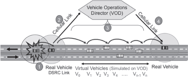
FIGURE 4 Mixed evaluation of real and virtual connected vehicles with the GrooveNet platform. The three vehicles in the circles are real vehicles communicating with short-range wireless communication (using the IEEE 802.11p/WAVE protocol) on the street. The remaining vehicles are simulated to facilitate communication between real and virtual vehicles. This platform allows for scalable and high-fidelity evaluation of vehicle-to-vehicle and vehicle-to-infrastructure network protocols. DSRC = dedicated short-range communication; V = virtual vehicle.
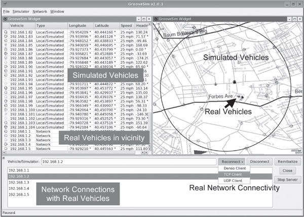
FIGURE 5 GrooveNet hybrid simulation demonstrating hundreds of virtual vehicles communicating with five real vehicles in the city of Pittsburgh, Pennsylvania. See text for discussion.
TRAFFIC CONGESTION ANALYSIS
To better understand empirical models of traffic congestion in different street topologies across the nation, and to develop sound traffic prediction and congestion-aware fastest-path routing algorithms, it is necessary to analyze large-scale traffic mechanisms. We have developed a traffic analysis tool, AutoMatrix, that simulates and routes over 16 million vehicles on any US street map and provides real-time traffic routing services with hierarchical and synthetic traffic matrices (Figure 6). Using this tool, we are able to investigate the design of adaptive routing strategies, methods to mitigate congestion, and ways to better use traffic network resources. Vehicles are modeled to be car following, have speed variations, communicate periodically, and be capable of multiple distributed and centralized routing algorithms.
AutoMatrix operates on a graphics processing unit (GPU) and so is capable of very large-scale microsimulation and traffic analytics. We have implemented A* routing, which executes each vehicle’s search for a fastest path between its origin and destination in a parallel processing manner on the GPU. AutoMatrix is capable of hierarchical routing so routes with different levels of details are possible.
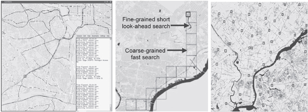
FIGURE 6 AutoMatrix real-time traffic congestion modeling and congestion-aware traffic prediction and routing algorithm design. (Left) Traffic congestion simulation showing more than 800,000 vehicles in Washington, DC. (Center) Hierarchical routing showing one vehicle’s coarse-grained route (in large boxes), which is determined at the beginning of the trip. The real-time congestion-aware fine-grained fastest route shows the ¾-mile route ahead of the vehicle. (Right) Thousands of vehicles (each small box represents a vehicle), each with unique origins and destinations, routed with real-time congestion-aware fastest-path routes around Philadelphia.
Vehicles can be guided with adaptive routing—the assigned route “responds” to changes in congestion patterns and reroutes the vehicle to the updated fastest path. By modeling point-based congestion, such as blocked lanes due to vehicle breakdowns or accidents, we can model queuing effects as vehicles back up and congestion spreads through the region.
Using these approaches, AutoMatrix has the potential to improve response time to traffic incidents by advising drivers to take the updated fastest path to their destination. We are working to use live traffic congestion data to support the needs of urban transportation operation centers.
CONCLUSION
The future of the automobile lies in the design and development of new vehicles that are programmable, connected vehicles, and networked traffic centers. These efforts are a step toward safer, more efficient, and more enjoyable commuting with automobiles.
REFERENCES
Duri′c P, Miladinov-Mikov M. 2008. Some characteristics of drivers having caused traffic accidents. Medicinski Pregled 61(9-10):464–469. Available online at www.ncbi.nlm.nih.gov/pubmed/19203062.
NHTSA [National Highway Traffic Safety Administration]. 2009. Safety Recalls, ID: 09V218000. Washington, DC: US Department of Transportation. Available online at www.safercar.gov.
Schäuffele J, Zurawka T. 2005. Automotive Software Engineering: Principles, Processes, Methods, and Tools. Warrendale PA: SAE International.


