
4
WIND TURBINE ROTOR DESIGN ISSUES
Wind turbine rotor blades are a high-technology product that must be produced at moderate cost for the resulting energy to be competitive in price. This means that the basic materials must provide a lot of long-term mechanical performance per unit cost and that they must be efficiently manufactured into their final form, including the cost of sufficient quality control. Unless a material choice and fabrication system can satisfy both of these requirements, it will not be appropriate for advancing the state of the art for economical production of power from the wind.
Both fiberglass-reinforced and wood/epoxy composites have been shown to have the combination of strength and low material and fabrication costs required for competitive blade manufacture. Their fabrication requirements and constraints, the current state of their materials database, and the areas where further research could advance their efficient use are, however, often quite different. The gradual evolution of wind turbine configuration and rotor designs also places a continuing demand on both systems to meet new requirements. In turn, the strengths and limitations of each material system also feed back into the process of system configuration selection and detailed design, as any design that cannot be efficiently produced will be at a competitive cost disadvantage. A really good design will already include the compromises necessary so that it can be effectively manufactured with acceptable quality in the material system chosen. A number of these considerations are discussed below.
AIRFOIL EVOLUTION
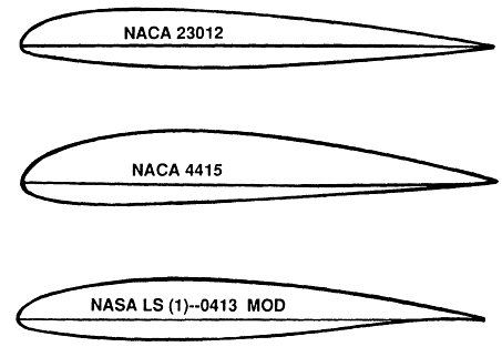
Early wind turbine blades typically used airfoil shapes borrowed from helicopter or low-speed aircraft use, such as the NACA 23xxx or 44xx series (Figure 4-1). These airfoils have shapes that are everywhere convex and in particular do not have a concave or reflex aft portion. While these were a natural starting point, they were found to be sensitive to the buildup of insects on the leading edge, which caused substantial loss of power output for many wind turbine designs.
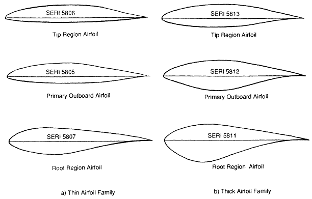
Further evolution of airfoil choice in view of field experience has led to the use of the more modern Wortmann or NACA laminar designs, as well as the aft loaded LS-1 type. These airfoil designs generally employ a reflex or concave aft portion, which feature is also evident on the special-purpose SERI wind turbine airfoils (Figure 4-2). That concavity effectively eliminates certain manufacturing processes, such as filament winding, from consideration for producing the outer airfoil shell. While it also forces some modification to the female mold fabrication technique, both fiberglass and wood/epoxy composites have successfully been produced in reflex shapes without significant cost penalty.
Precise control of airfoil geometry is quite important in providing blades with consistent aerodynamic properties. Small variations in outboard airfoil camber (±1/4 percent of chord) or twist (±1/4°) can lead to substantial aerodynamic imbalance and rotor and turbine life reduction. For stall-controlled machines, off design peak power can further reduce cost-effectiveness by either overstressing driveline and generator components, and thereby increasing replacement costs, or by reducing total power output and revenue. This need for aerodynamic consistency and accuracy has led to the adoption of molding as the fabrication method of choice for both fiberglass
and wood/epoxy composites, as it provides control right at the outer aerodynamic surface, which determines ultimate performance. Both material systems are able to provide the complete range of outboard airfoil shapes currently of interest.
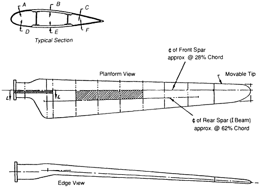
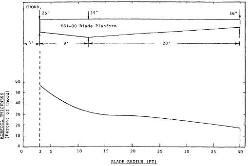
While the outboard portion of the rotor changes little with material choice, the inboard region is a different matter. Fiberglass rotor blades often incorporate a large amount of inboard planform area and twist, and may carry the maximum chord quite far in toward the root (Figure 4-3) (Stoddard, 1989). For a given rotor diameter, this will produce the most power, albeit at the cost of a significant increase in total blade surface area and materials. The flat sheet nature of the veneers used in wood/epoxy construction does not lend itself well to large inboard planform and the twist and the double curvature surfaces that result. Instead, a gradual transition from the inboard airfoil shape to an oval root is performed over the inner third of the blade (Figure 4-4). To regain the minor power loss due to lessened inboard planform area, a slight increase in blade length is provided. Since the turbine rotor designer is free to sweep energy out of the flow at whatever radius provides the least rotor cost, this is an effective solution because the cost of the slight extra length is small compared to the large reduction in inboard planform area. Low wind start-up torque is reduced, which could be a limitation for some turbine designs, but the reduction of planform area also reduces storm wind loading on the turbine as a whole, so the cost trade-off at the system level may or may not be favorable depending on start-up requirements.
AERODYNAMIC TIP BRAKES
Turbine designs, which incorporate full span blade pitch control, can use that system to provide aerodynamic shutdown. Many current turbine designs, which use a mechanical brake for normal shutdown, do not have full span pitch control and must therefore depend on some other method of aerodynamic braking for safety. A great many methods have been tried, but most machines have used either a pivoting outboard tip section or a rotating tip plate.
The pivoting tip design has been dominant for the Danish fiberglass blades. The usual arrangement employs a centrifugal latch that releases the tip when an overspeed condition occurs. The tip is then allowed to move outboard, and a cam rotates it (in pitch) until it is perpendicular to the plane of rotation, thereby providing the drag needed to slow the machine aerodynamically. The typical arrangement to accomplish this uses steel parts for the mechanism, including cam, follower, attachment feet, and the structural tubes, which carry the tip loads back into the inboard blade. The feet that form the attachment to the blade are typically glassed (i.e., embedded in resin/fiber) onto one of the blade shells to secure the mechanism to the inner blade and to secure the tip to the pivoting tube.
Tip failures have been observed with this system, typically near the cut that separates the tip from the inner blade. That is where the bending moment in the tube is at the maximum, and indenting or scuffing from a loosely fitting bearing or collar can help initiate a failure. Damage in this area due to saw cuts, welding, or other manufacturing operations has also been known to lead to tube failure. These problems are not generally due to insufficient fatigue knowledge of the steels used, but rather to manufacturing and quality control issues, and the fact that a small geometric cross section for the embedded tube leads to rather high working stresses. The bonded retention of the assembly to the blade has generally been quite satisfactory (Poore and Patterson, 1990; Stoddard, 1989; Faddoul, 1981).
Composites can be considered as a replacement for steel in this high-stress fatigue application. Fiberglass, while strong enough, has a low modulus that leads to large angular deflections and consequent problems with bearing alignment. Carbon fiber has the stiffness, strength, and fatigue endurance needed for the tip tube application, but it is considerably more costly than steel. However, as the cost of carbon fiber drops, the weight
savings and corrosion resistance that it provides may make it attractive for this application.
The wood/epoxy composite blades produced by Howden also use the pivoting tip arrangement. While operating hours and machine numbers are not nearly as large as for the Danish designs, application with the wood/epoxy material system has not shown any unusual problems to date.
The Enertech and ESI designs of U.S. origin both used pivoting tip plates for overspeed protection. These were retained in place using threaded rod epoxy bonded into a veneer buildup at the blade tip. The load takeoff principle is identical to the well-tested root stud method and has proven highly reliable in service, except for cases of massive overspeed due to failure of the latch mechanism to deploy. This is not a material knowledge or fatigue problem.
Future wind turbines may employ techniques such as outboard blade ailerons or boundary layer control for overspeed protection. Such methods are not only potentially preferable from an aerodynamic standpoint, but also require much less disruption of the primary load path within the blade and could thereby reduce the possibility of long-term fatigue failure as well.
BLADE ROOT RETENTION
Glass-Reinforced Plastic (Grp) Blade Roots
For both fiberglass and wood/epoxy composites, the blade-to-hub interface requires a high-performance fatigue design that can take loads from the composite blade structure into a metal hub assembly. Mating these dissimilar materials in high-cycle fatigue has been a serious design challenge in both material systems.
Two major Danish fiberglass blade builders used a flanged root design. One variation, called the Hutter root after its originator, used thick unidirectional roving bundles wrapped around tubular bushings within the flange (Figure 4-5). These thick bundles bent around the root radius and terminated well up inside the root tube, so that an extensive bonding area was provided to the skin and spar reinforcing. Since the bolts attaching the blade to the machine passed through the flange bushings, the blade was
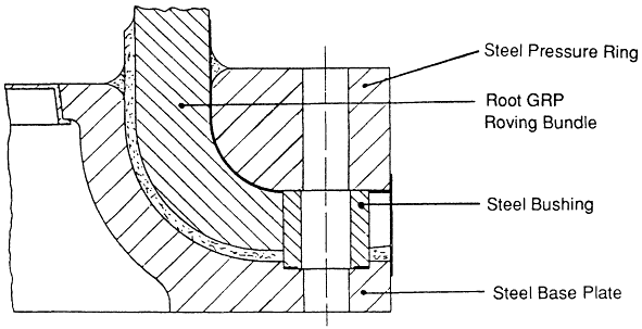
Figure 4-5
Flanged GRP blade root design. Source: Stoddard (1989).
mechanically captured both via the bolts/bushings and the flange clamping plates. Polyester-based filler material was used to fill the gaps between the hub, metal clamping plates, and the GRP flange to render the assembly as stiff and free of movement as possible.
The other major variation of the flanged root used root roving material that was molded uniformly outward to form the flange, after which the flange drilled and metal bushings were added. While the extra security of a wrap around the bushings was no longer present, mechanical clamping between the hub and flange plates provided positive mechanical capture. While filler material was again used to resist movement and render the final assembly as solid as possible, like the Hutter root, this design again did not depend a metal-to-GRP bond. Given the modulus and strain values of these designs, some motion between metal and GRP appears virtually unavoidable in the long run.
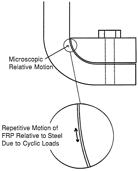
Both of these flanged root designs encountered considerable trouble in service (Stoddard, 1989). Partly due to quality control and manufacturing problems, and partly due to the inevitable shrinkage of polyester upon cure, the GRP flange was often not clamped well between the hub and flange plates. Once some gap occurred, the blade root was free to move somewhat and could then begin to reduce the filler material to powder. At the same time, the GRP bundles would begin to move relative to the steel flange plates (Figure 4-6) and would often floss deep grooves into their surfaces due to the repetitive motion. Loss of root stiffness and the appearance of fine powder at the root were the symptoms of this degeneration. It was estimated by Stoddard (1989) that this problem was observed on 5 to 10 percent of the blades in service and was expected on 30 to 50 percent of the blades, given operation and management attention. This amounts to over 20,000 blades.
A procedure called a root pack was developed to deal with these root problems. In essence, the flanges were removed, and fresh filler material was added to take up the gaps and restore a tight fit. In many instances the bushings were shortened or recesses were machined into the flange plates so that the bolt pretension could clamp directly against the GRP flange. Bushings with a carefully selected crushing stress were also employed in some of the later designs, so that the GRP and steel bushing could each share some of the bolt preload, which was the original design intent of all the flange designs. It should be pointed out that some known flanged blades have over 5 years of operation with no problems and no root pack.
There is no doubt that the root pack procedure extended the useful life of many blades in the field. However, the increased clamping stresses within the GRP may now be taking a toll, as long-term tensile failure right through the fiber bundles has now begun to appear (Poore and Patterson, 1990). While a well-designed, well-manufactured flanged root may offer life of several years, it does not yet appear able to offer the desired decades of life. This is true even though the blades in question are generally less than 10 m in length. Life expectancy is only likely to get worse as larger blades with increased gravitational bending moments are designed.
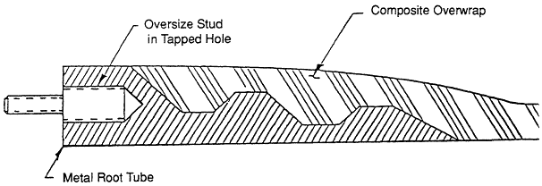
Another class of fiberglass root design is based on a tapered metal tube that is bonded to the root region of the blade (Figure 4-7a). The tubes may be interior, exterior, or both and may occur with or without through bolts. For its long-term fatigue performance, this class of roots generally depends on a metal-to-GRP bond to transfer load via shear from one material to the other. These steel root tubes are provided with a steel flange so that they can be bolted to the hub assembly. The increased amount of metal required for this class of retention may be more costly compared to the types where the flange is formed directly from the GRP. However, roots of this sort appear to be reliable when properly designed and manufactured and have served well up to the present time.
WOOD/EPOXY BLADE ROOTS
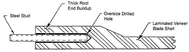
The method of root retention for wood/epoxy composite blades has evolved along a quite different path than the flanged roots typical of GRP blades. While internal tubes with bolted flanges were briefly considered in the earliest days of the National Aeronautics and Space Administration's (NASA) MOD 0A program, they were quickly rejected as too costly and difficult. Attention was directed instead to the use of threaded steel studs, epoxy bonded directly into a thickened region of root laminate (see Figure 4-7b). Since the MOD 0A program required supporting a nearly 18.3-m (60-foot) blade on an 0.5-m (18.625-inch) bolt circle to match the existing hub, high mechanical performance was a necessity right from the start. While a simple bonded, threaded rod could not meet the one-time load and fatigue requirements, tapered designs were soon created that could meet the requirements with some margin to spare (Faddoul, 1981).
Once the difficult requirements of MOD 0A had been met, the small blade root designs for Enertech and ESI were not difficult, as a relatively larger and more optimally shaped oval bolt pattern could be specified at the time of blade design. This allowed a reduction in the number of studs, from the 24 of MOD 0A to only 10 or 12 for the smaller blades. Since the cost of the studs themselves is a substantial portion of the total root cost for a wood/epoxy blade, this reduction of part count was important from a cost standpoint. For the 20.4-m (67-foot) Westinghouse blades, a return to 24 studs was appropriate due to the much increased loads of that 600-kW, 43.3-m (142-foot) diameter machine.
The two primary manufacturing concerns for a stud root are that the epoxy completely fill the drilled hole without significant voids and that the studs be accurately coplanar so that stresses are not induced when mated to the wind turbine hub. Proper equipment and procedures have been developed to achieve these ends, and many fatigue tests of bonded studs, both singly and in whole roots, have shown that the system can readily tolerate the minor variations of a good manufacturing process.
Field experience with the Gougeon bonded stud root has been excellent. While some roots have failed in cases of machine runaway, these were at loads well beyond any intended design conditions. Fatigue failure has not been recorded for any of over 4000 blades in the field, with known use hours on some units at or beyond 25,000. Recent examination of a stud from the large-scale Westinghouse machine, with 17,000 hours, showed no evidence of fatigue damage. The extensive static and fatigue testing, which supported the early design efforts for this root retention type, apparently provided a solid basis for successful field application (Faddoul, 1981).
Other efforts to employ wood/epoxy-bonded studs have not been uniformly successful. The Howden 33-m turbine used this basic approach but is known to have had root problems. This choice of material system and root type is not enough to ensure success by itself. As in other parts of the wind turbine rotor, appropriate engineering design practice and fabrication technique are also required for success.
Theoretical analysis has indicated a small loss of performance when the bonded stud is used with GRP rather than wood/epoxy, but the performance levels are not reduced enough to prevent their successful application to that material system. Indeed, some of the Danish blades are now produced this way, rather than with the original flanged root designs.
BLADE JOINING
Efficient field joining of blade sections has not yet emerged as a major issue for blade design and manufacture, because most of today's machines are small enough that shipping the blades in one piece is not much of a problem. However, conceptual studies have indicated potential cost and weight advantages for two bladed rotors that are essentially one continuous structural piece due to the use of a composite ''flow through'' hub (Figure 4-8). This system entirely eliminates the normal root retention and, in
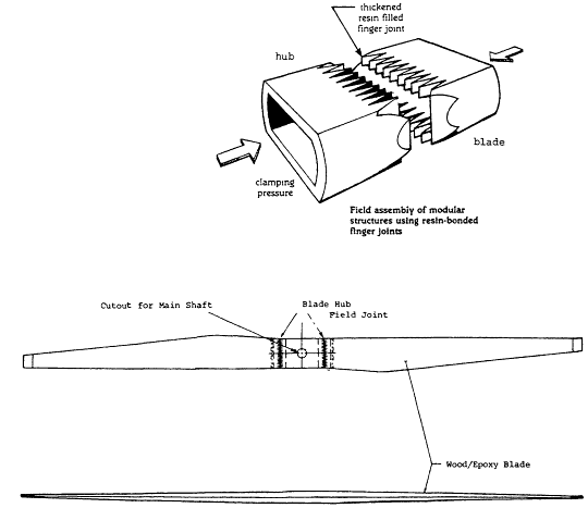
Figure 4-8
All-wood/epoxy composite Hub. Source: Stroebel et al. (1984).
conjunction with a teeter system, needs to carry only net thrust and torque to the wind turbine. The resulting design is structurally efficient and should have excellent long-life fatigue potential, but it will require some form of field assembly to allow rotors to be shipped in pieces of convenient size. A cost-effective, fatigue-proven joining system for both fiberglass and wood/epoxy surely seems within reasonable technical reach but has not been developed and verified at this time. Such a field joining technique would also be of great value for vertical axis machines, whose curving blade shape makes them particularly difficult to ship in large pieces. Many other ways to use such a system to reduce machine-installed cost may be discovered once it is available and optimized.
BLADE DESIGN CONSIDERATIONS
Fiberglass Blades
The least-expensive structural material for fiberglass blade construction is unidirectional roving. This is a high value-added material
for the manufacturer and, due to its straight fiber path and low resin content, is also one of the best-performing fiberglass forms on the basis of strength and stiffness to weight. It is therefore of economic and structural advantage to employ this material for as much of the primary structure as possible, consistent with efficient fabrication. Its limitations are that it does not have the thickness uniformity of fabrics and does not distribute well onto vertical or near-vertical mold surfaces. This can lead to fabrication difficulties near the blade root.
While conventional filament winding and transverse filament tape (TFT) are not applicable to the most recent classes of airfoils, with their generally reflex trailing edge regions, these fabrication techniques could still be considered for the primary structural spar in a spar/skin blade construction. It would be necessary for spar fabrication by winding to be very low cost to compete effectively with the unidirectional roving reinforcement mentioned above, but there may be designs or production levels for which that is possible. The method would gain considerably if some of the cost or complexity of root formation could be included efficiently in spar construction, as might be the case for winding directly over the root fitting.
While spar/shell construction has many attractions, it must overcome at least two significant structural handicaps. The first is that it is difficult for the spar to be stiff enough edgewise to prevent large strains in the blade trailing edge, which would lead to early shell cracking and failure. This could be handled by putting more active material in the blade shells so they carry more of the edgewise loads themselves or by the addition of a unidirectional trailing edge spline. The second handicap is that material concentrated in the spar rather than spread through the blade shell results in thinner skin laminates, which then need more buckling support and are easier to damage in the field. Simply put, it is difficult to beat the structural efficiency and ruggedness of a stressed skin design, and significant fabrication economies must exist for the spar/shell construction to be competitive with it. This is fundamental in assessing likely blade fabrication or material improvements.
The foregoing notwithstanding, it should be pointed out that several Danish blades, such as LM, MAT, and Vestas, are currently produced with spar/shell construction and are performing successfully. WEG is producing a wood/epoxy spar/GRP tail panel hybrid that also is performing well. Only time and further economic competition can show if such designs will prove to be the most cost-effective in the long run.
Even stressed-skin fiberglass blades often need panel stiffening in the relatively flat aft blade area, especially inboard where the span from shear web to trailing edge can be particularly large. Expanded foams are often used to provide the required panel support, due to their light weight, moderate cost, and easy formability. However, foams can be impact damaged by rough handling, and their long-term fatigue properties are not well characterized for the numbers of cycles typical of wind turbine blades, particularly under conditions of variable outdoor environment or in the presence of damage. Honeycomb is another skin-support possibility, but it has received little attention due to its cost and greater formability problems compared with other choices.
A panel-stiffening material used in a great many fiberglass blades to date is a felt-like material called core mat. Core mat is inexpensive and easy to conform to complex blade shapes. It is very light in the resin-free condition and, while it does absorb considerable resin, still has acceptably low density once bonded in place. Since this material is somewhat fibrous in nature, it may have rather good long-term fatigue properties, but at present this useful component of blade fabrication is not characterized in long-term fatigue. However, it can be said that shell-cracking problems seen in the field do not appear to be caused by core mat limitations for the kinds of lifetimes and cycle counts currently achieved. This situation could change for larger blades with larger panel sizes and deflections, but data for a quantitative assessment of these possible problems do not exist.
Since most blades are formed in female half-shell molds, joining of the blade shell halves and the interior shear webs is a major part of the overall manufacturing process. A mixture of polyester resin and talc called
plasterite has been extensively used as a filler in the joining operations by certain fiberglass blade manufacturers. This material is stiff enough to attract considerable load when used in large quantity, as has often been the case, but is not possessed of fibrous reinforcement for strength and crack stopping in long-term fatigue. Another problem is shrinkage after fabrication, which builds in residual tensile stresses that the material is not well suited to handle. The only real attraction of this material appears to be its low cost, since the unfavorable combination of stiffness without strength appears to lead to high-cycle shell cracking, after crack origination in the bulk plasterite bonding material. Adequate fatigue characterization of this material does not exist, and it may be an impending problem for many blades now in use in the field. Other, better-suited, fillers with greater fatigue capability and suitable cost, handling, and health properties may be an important component in providing long-term blade life at a competitive cost. Test data to identify, select, and predict the performance of better fillers are not available to the blade industry at this time.
Another area of concern to the blade designer is the selection of blade skin-reinforcing materials. It is well known that conventional fabrics with a lot of fiber crimp due to the weaving process suffer in high-cycle fatigue due to resin breakdown and fiber stress concentrations at the intersections in the weave. So materials with less fiber crimp will be preferred in high-cycle fatigue wind turbine applications. However, this still leaves a wide selection of reinforcement styles across a broad range of costs in terms of the basic fiberglass chosen. A question of the role and durability of chopped mat and double bias constructions in the high-cycle environment also exists. Test data to allow a rational choice of the most cost-effective reinforcement are scant.
Another basic question exists in the choice of resin system. While epoxies are generally conceded to have the best long-term fatigue strength, they are considered by some to be more difficult to work with and too expensive for wind turbine blade fabrication. Current production has, therefore, concentrated primarily on the low-cost polyester system, with some designers opting for the somewhat higher-cost vinylester systems. While there is no doubt that vinylester is stronger at low- and moderate-cycle levels, it also appears to have a much larger fatigue effect than polyester. Some current data appear to suggest (Burrell et al., 1986) that, at 10 million cycles and above, polyester may, in fact, outperform the more expensive vinylester. An appropriate resolution of this question would obviously benefit cost-effective blade manufacture.
Wood/Epoxy Blades
The fundamental fatigue database for wood/epoxy composite is in good condition compared to that for GRP, as has been pointed out elsewhere. However, a number of topics to further improve the cost-effective use of this material system do exist. One of these, the cost-effective field joining of fabricated pieces for advanced rotor types, has already been mentioned. Additionally, research work by Gougeon Brothers completed under an SBIR contract to the Department of Energy (Bertelsen and Zuteck, 1989) has shown that advanced laminate splice joints can allow bulk laminate mechanical performance to approach that of unjointed material, but proving out practical manufacturing methods to realize this promise has not yet been accomplished. Another area of possible interest is that of alternative species to the Douglas fir used for the bulk of the previous work.
All of the above topics could improve the effectiveness of the wood/epoxy material system within the current design envelope. However, substantial gains may also be made by expanding the design envelope for the material. As was mentioned previously, the veneer sheets used with this construction technique constrain the acceptable blade geometries because they can accept only a very small level of double curvature without splitting or creating excessive resistance to the vacuum-molding forces. In this regard the problem is much like that for molding thermoplastic sheets, which are also relatively stiff and lack the convenient "drape" of conventional fiberglass
materials. There may be many ways to move beyond current restrictions. For instance, high-temperature forming processes may be able to push the wood veneer into its plastic range and provide forming possibilities that room-temperature molding cannot. Or it may be possible to preprocess the veneer into a form that is much more conformable than the current full veneer sheets but that is still easy and efficient to handle. The fact that the database for wood/epoxy is in good condition for wind turbine blade fatigue design does not mean that further significant advances in this material system are not available, but rather that they may lie in somewhat different areas than for fiberglass.
Finally, both material systems can benefit from explicit feedback into the aerodynamic design process, so that the shapes specified exploit the strengths and cost efficiencies of each to the best overall effect.
Whichever material system is used, long-term fatigue performance will benefit from using simple external shapes with primary load paths that are as straight as possible, particularly in the highly loaded root and root transition areas. Minor power losses due to simplification of the inboard rotor geometry can be offset by a slight increase in rotor length, resulting in a potentially lighter and lower-cost blade of equal energy capture performance and superior long-term fatigue life. New blade designs should explicitly consider this structurally beneficial approach at the aerodynamic design phase.
RECOMMENDATIONS1
Grp
-
Fatigue data that can resolve whether polyester or vinylester is the appropriate resin for high-cycle wind blade use should be obtained. Common E-glass reinforcing, such as unidirectional fabric and roving, double bias/mat, knit triaxial, and chopped strand mat should be investigated to determine which perform best with these low-cost resins.
-
Filled bonding material (such as plasterite) appears to have caused fatigue failures of blade shells. Testing to identify and fatigue qualify a low-cost bonding material would be valuable.
-
Static and fatigue data (including shear) to define the mechanical performance of core mat or other low-cost core material are needed to assure that fatigue design goals will be met.
Wood/Epoxy
-
Provide proof of the static and fatigue performance of a low-cost field joining technique for use with flow-through rotor concepts and future large or complex shape rotors (such as MOD 5 or Darrieus).
-
Investigate the potential for low-cost techniques to mold wood/epoxy laminate into double curvature shapes that cannot be made with current methods. Confirm fatigue performance of the resulting laminate.
Generic
Both GRP and wood/epoxy rotors could achieve cost and fatigue benefits from an all-composite one-piece rotor design. The potential life-cycle benefits of such designs should be studied and appropriate composite hub designs identified.
REFERENCES AND BIBLIOGRAPHY
Bertelsen, W. D., and M. D. Zuteck, 1989. Investigation of Fatigue Failure Initiation and Propagation in Wind-Turbine-Grade Wood/Epoxy Laminate Containing Several Veneer Joint Styles. September. DOE/SBIR, Contract DEAC02-86ER80385, Phase 2 Report, Gougeon Brothers, Inc.
Burrell, P., T. McCabe, and R. de la Rosa, R. 1986. Cycle Test Evaluation of Various Polyester Types and a Mathematical Model for Projecting Flexural Fatigue Endurance. Presented at the International Conference on Marine Applications of Composite Materials , March 24-26, pp. D-1, D-5.
Faddoul, J. R. 1981. Test Evaluation of a Laminated Wood Wind Turbine Blade Concept. DOE Report DOE/NASA/20230-30, NASA TM-81719. U.S. Department of Energy, Washington, D.C.
Gougeon Brothers, Inc. 1985. Engineered Laminates, Technical Bulletin No. 1, Bay City, Michigan, April.
Miley, S. J. 1982. A Catalog of Low Reynolds Number Airfoil Data for Wind Turbine Applications. Prepared by the Department of Aerospace Engineering, Texas A&M University, for Rockwell International Corporation, Energy Systems Group under Subcontract No. PFY12781-W.
Musial, W. D., C. P. Butterfield, and D. Handman. 1985. ESI-80/EPRI Test Program.
Poore, R. Z., and M. Patterson. 1990. 7.5 Meter Blade Condition and Service Experience. Presented at American Wind Energy Association Conference, September 27.
Stoddard, F. S. 1989. Field Problems with Wind Turbine Rotors. NAS presentation before Committee on Assessment of Research Needs for Wind Turbine Rotor Materials Technology, November 7-8, Washington D.C.
Stoddard, F. S., and M.D. Zuteck. 1987. Blade Retention Fatigue: Symptoms, Causes, Cures. Presented at the Windpower 87 Seminar, October 5.
Stroebel, T., C. Dechow, and M. D. Zuteck. 1984. Design of an Advanced Wood Composite Rotor and Development of Wood Composite Blade Technology. DOE Report DOE/NASA/0260-1, NASA CR-174713. U.S. Department of Energy. Washington D.C.
Tangler, J. 1990. Advanced Airfoils/Blade Development at SERI. NAS presentation, January 22-23, Washington, D.C.


