
Status and Challenges for Inertial Fusion Energy Drivers and Targets
A brief introduction to the concepts of drivers, targets, and implosion mechanisms was given in Chapter 1. In the first part of this chapter, the committee provides a more detailed discussion of alternative strategies for driving the implosion of targets and explains why terms such as “direct drive” and “indirect drive” are more accurate descriptors for some driver-target pairs than for others.
In the second part of this chapter, the committee takes up the status and future R&D needs of the three main driver candidates: lasers (which include diode-pumped, solid-state lasers and KrF lasers); heavy-ion accelerators; and pulsed-power drivers. This discussion of driver approaches is based on input received from proponents who are technical experts in the field.1 As such, the R&D challenges and investment priorities for moving each approach forward to a major test facility— Fusion Test Facility (FTF)—are discussed independently of one another—that is, as if a decision had been made to choose that particular approach as the best option for inertial fusion energy (IFE). The committee recognizes that a down-selection to one particular approach will have to be made and does not mean to suggest that all of the approaches should be funded simultaneously at the levels indicated in this chapter. A discussion of how these approaches might fit into an integrated program with down-selection decision points is given in Chapter 4. Throughout this chapter material is drawn from the report of the committee’s supporting Target Physics Panel (see the Preface); the Summary from the unclassified Target Physics Panel report appears as Appendix H.
__________________________
1 The experts who gave presentations to the committee are listed in Appendix C.
Conclusions and recommendations are given within the sections. General conclusions appear at the end of this chapter.
METHODS FOR DRIVING THE IMPLOSION OF TARGETS
A large number of target designs have been studied and proposed for IFE power plants. As explained in Chapter 1, these targets may be categorized according to the method used to drive the implosion (to compress the fuel to high density) and according to the method used to bring the fuel to the required ignition temperature. In addition, targets are sometimes categorized according to illumination geometry. For example, in some target designs, the incoming driver beams are arranged uniformly around the target to approximate spherical illumination. At the National Ignition Facility (NIF), the beams are arranged in four cones that illuminate the inside wall of the hohlraum from two sides (the poles of the cylindrically symmetric target). Historically, there have also been illumination geometries that more strongly illuminate the equatorial area of the target. Finally, for pulsed-power IFE systems, there may be no driver beams at all; the electrical energy is coupled directly to the target by the pressure of the magnetic field produced by the drive current.
The two principal methods of driving laser implosions are indirect drive and direct drive (see Figure 1.4). For ion accelerators, there is nearly a continuum between indirect drive and direct drive.
The three principal methods proposed to ignite the fuel are referred to as hot-spot ignition, shock ignition, and fast ignition. For indirect drive, there is some thermal inertia or heat capacity associated with the cavity surrounding the fuel capsule and with the ablator itself. It is more difficult to achieve the rapid rise in temperature and pressure with indirect drive because of the thermal inertia of the hohlraum. Shock ignition requires rapidly rising drive pressure at the end of the drive pulse. Consequently, shock ignition is usually associated with direct drive. Hot-spot ignition and fast ignition are the main ignition modes for indirect drive. All three modes of ignition necessarily ignite only a small fraction of the fuel. The thermonuclear burn then propagates into the bulk of the fuel.
Implosion Requirements
A number of conditions must be satisfied to produce ignition and reactor-scale gain.2 These conditions are described in detail in Appendix A; in this section, the committee gives a brief overview.
__________________________
2 R. Betti, University of Rochester, “Tutorial on the Physics of Inertial Confinement Fusion for Energy Applications,” Presentation to the committee on March 29, 2011.
Symmetry
Ideally, the final configuration of the imploded fuel should be nearly spherical. For laser-driven and heavy-ion-driven implosions, this requirement imposes conditions on the uniformity of the light, X-ray, or ion flux driving the target, and also on the initial uniformity of the target itself. For example, if the target is driven more strongly near the poles, the final imploded configuration might be shaped like a pancake. If the equator is driven more strongly, the imploded configuration might resemble a sausage. The greater the convergence ratio3 of the target, the greater the precision required in direct drive—for example, in drive pressure or shell thickness. For most laser target designs, this convergence ratio lies between 20 and 40.
Sausagelike, pancakelike, dumbbell-like, or even doughnutlike asymmetries are low-order asymmetries in the sense that the wavelength of the departures from spherical symmetry is comparable to the size of the compressed fuel configuration. Energy imbalance among the beams is one possible type of error leading to low-order asymmetries; beam misalignment is another.
Fluid Instabilities
In addition to the low-order asymmetries, higher-order asymmetries are also important. Small perturbations on the surfaces of the fuel and ablator shell can grow as the shell is accelerated.
Unless the initial layer surfaces are very smooth (i.e., perturbations are smaller than about 20 nm), short-wavelength (wavelength comparable to shell thickness) perturbations can grow rapidly and destroy the compressing shell.
Mix
Similarly, near the end of the implosion, such instabilities can mix colder material into the spot that must be heated to ignition. If too much cold material is injected into the hot spot, ignition will not occur.
Density
Most of the fuel must be compressed to high density, approximately 1,000 to 4,000 times solid density. (In the case of hot-spot ignition, the central (gaseous) portion of the fuel is compressed to lower density.) Compression to such high densities demands that the fuel remain relatively cool during compression—technically,
__________________________
3 For hot-spot ignition, the convergence ratio is usually defined as the initial target radius divided by the final hot-spot radius.
very nearly Fermi-degenerate. Otherwise, too much energy is required to achieve the required density. This requirement in turn places stringent constraints on the pulse shape driving the target. The drive pressure must initially be relatively low (on the order of 1 Mbar); otherwise the initial shock wave that is created will heat the fuel to an unacceptable level. The pressure must then increase to produce a sequence of carefully timed shock waves to compress and ignite the fuel in the hot spot. Moreover, if the beam–target interaction produces too many energetic electrons or photons that can penetrate into the fuel and preheat it, efficient compression is not possible.
Fuel compression is related to an important quantity, the product of fuel density and fuel radius (ρr). This quantity is important for two reasons. The first is related to ignition. Ignition occurs when the rate of energy gain in the fuel exceeds the rate of energy loss. The igniting fuel gains energy as the fuel is shocked and compressed, but it must also gain energy by capturing its own burn products; specifically, in the case of deuterium-tritium fuel, it must capture the alpha particles that are produced. In this case, the ρr of the hot spot must exceed approximately 0.3 g/cm2, the stopping range of an alpha particle in igniting fuel.4 The second reason that ρr is an important quantity is because it determines the fraction of fuel that burns. This fraction is approximately given by ρr /(ρr + 6), where ρr is given in g/cm2. To achieve high target energy gain needed for laser inertial fusion energy (IFE), the ρr of the entire fuel, not just the hot spot, must be of the order of 3 g/cm2. It is noteworthy that if one were to achieve such a ρr with uncompressed fuel, the fuel mass would be of the order of 1 kg. Heating 1 kg to 10 keV requires about 1012 J (~200 tons of high explosive equivalent) delivered to the fuel, and the resulting fusion yield would be 100 kton. These are perhaps the most important reasons why a small mass of fuel, typically 1 to 10 mg, must be compressed to high density.
Implosion Velocity
As noted above, ignition occurs when the rate of energy gain in the fuel exceeds the rate of energy loss. For hot-spot ignition, an implosion velocity on the order of 300 km/s is required to provide adequate self-heating of the fuel. It is fortunate that this velocity corresponds to a specific energy that is more than adequate to compress the fuel to the required density. However, since the ignition velocity exceeds the velocity needed for compression, it may be possible to improve target performance by separating the compression and ignition processes. This possibility is the reason for considering fast ignition and shock ignition.
__________________________
4 R. Betti, University of Rochester, “Tutorial on the Physics of Inertial Confinement Fusion for Energy Applications,” Presentation to the committee on March 29, 2011.
Laser Targets, Direct and Indirect Drive
As discussed above, there are two principal ways to drive laser targets, direct drive and indirect drive. Both have advantages and disadvantages. Choosing between the two approaches has been, and remains, one of the most thoroughly (sometimes hotly) debated issues in inertial fusion. The choice is complicated because it involves not only target physics but also issues associated with target fabrication, reactor chamber geometry and wall protection, target injection, alignment tolerances, and target debris. Moreover, target performance depends on the wavelength and bandwidth of the laser light used to illuminate the target. Traditionally this dependence has coupled the choice of direct vs. indirect drive to the choice of laser, further complicating the scientific issues.
It is important that the laser–target interaction does not produce energetic photons or electrons that can preheat the fuel and prevent proper compression. A number of laser–plasma instabilities are known to produce preheat. The product of laser intensity (power per unit area) and wavelength squared is a measure of the importance of such instabilities. The instabilities are less important at lower intensities and shorter wavelengths. Consequently, as explained later in this chapter, solid-state lasers that typically produce light with a wavelength of 1 μm employ frequency doubling, tripling, or quadrupling to obtain wavelengths that are more compatible with target requirements. KrF lasers intrinsically produce light with a wavelength of 0.25 μm and do not require frequency multiplication. Even at shorter wavelengths, important concerns and uncertainties remain, especially because the targets required for inertial fusion power production must be larger than the targets that have been experimentally studied. Instabilities are expected to be worse in the larger plasma scale lengths associated with these larger targets.
The high efficiency of coupling laser energy to the imploding fuel is usually considered the most important advantage of direct drive. In the case of indirect drive, a substantial fraction of the laser energy must be used to heat the hohlraum wall. Typically less than half the laser energy is available as X-rays that actually heat the ablator. On the other hand, the calculated efficiency of X-ray ablation is usually somewhat higher than the efficiency of direct ablation, partially offsetting the hohlraum losses. Nevertheless, the higher coupling efficiency of direct drive is reflected in the target gain curves (target energy gain vs. laser energy) shown to the committee. Specifically, for hot-spot ignition, the calculated target gain for direct drive at the same drive energy is roughly 3 times higher, or, alternatively, 1.5 times higher at two-thirds of the drive energy. (Higher gain and lower driver energy lead to improved economics for IFE.) If shock ignition (described below) turns out to be feasible for direct drive but not indirect drive, the difference in gain between direct and indirect drive for a given driver energy will be more pronounced.
Another potential advantage of direct drive is the chemical simplicity of the target. Laser direct-drive targets usually contain little high-Z material. In contrast, indirect-drive targets require a hohlraum made of some high-Z material such as lead. For this reason the indirect-drive waste stream (from target debris) contains more mass and is chemically more complex than the direct-drive waste stream. This issue is discussed more fully in Chapter 3.
Indirect drive also has a number of advantages. For indirect drive, the beams do not impinge directly on the capsule but rather on the inside of the hohlraum wall (see Figure 1.4). The radiation produced at any point illuminates nearly half the surface area of the target. Moreover, the radiation that does not strike the target is absorbed and reemitted by the hohlraum wall. Thus, there is a significant smoothing effect associated with indirect drive. Consequently, beam uniformity, beam energy balance, and beam alignment requirements are less stringent than they are for direct drive. For example, for direct drive, a typical beam alignment tolerance might be 20 μm. The NIF baseline indirect-drive target, however, can tolerate a beam misalignment of about 80 μm. Furthermore, although the hohlraum complicates the waste stream from the target, it also provides thermal and mechanical protection for the target as it is injected into the hot chamber. This protection enables the use of chamber wall protection schemes (e.g., gas protection) that are not available to direct drive; for instance, gas in the chamber produces unacceptable heating of bare, direct-drive targets. Moreover, the smoothing effects of the hohlraum allow greater flexibility in beam geometry (chamber design) than is the case for direct drive. Specifically, polar illumination is suitable for indirect drive. It is likely suitable for direct drive as well, but for direct drive it degrades performance relative to spherical drive.
A final advantage of indirect drive is not a technical advantage at all, but rather a programmatic advantage. Much of the capsule physics of indirect drive is nearly independent of the driver. Therefore significant amounts of the information learned on laser indirect-drive experiments carry over to indirect drive for ion-driven targets.
As for interactions with the chamber wall, direct-drive targets and indirect-drive targets have very different output spectra in terms of the fraction of energy in exhaust ions compared to the fraction of energy in X-rays. Specifically, for indirect drive a substantial fraction of the ion energy is converted to X-rays when the ions strike the hohlraum material. Partly because of the difference in spectra, different wall protection schemes are usually adopted for the two target options. For example, magnetic deflection of ions is an option that is being considered for direct drive while gas or liquid wall protection to absorb X-rays is usually favored for indirect drive. The issues of output spectra, target debris, chamber options, and target fabrication costs are discussed more fully in Chapter 3.
The NIF houses the world’s largest operating laser.5 The NIF team has selected indirect drive with hot-spot ignition and polar illumination for its first ignition experiments. Without modification, the NIF could also be used to study some aspects of direct drive such as the behavior of laser beams in plasmas having large scale lengths. With modifications to improve beam smoothness, NIF is also able to study polar direct drive with and without shock ignition.6 Such modifications are estimated to take 4 or more years to complete and cost $50 million to $60 million (including a 25 percent contingency added by this committee; see Chapter 4).7
In summary, both direct drive and indirect drive have advantages. The current uncertainties in target physics are too large to determine which approach is best, particularly when one includes all the related issues associated with chambers, target fabrication and injection, wavelength dependence, and so on. This conclusion leads to Recommendation 2-1, below.
Laser-Driven Fast Ignition
In laser-driven fast ignition the target is compressed to high density with a low implosion velocity and then ignited by a short, high-energy pulse of electrons or ions induced by a very short (a few picoseconds) high-power laser pulse.8 Fast ignition has two potential advantages over conventional hot-spot ignition: higher gain, because the target does not need to be compressed as much, and relaxed symmetry requirements, because ignition does not depend on uniform compression to very high densities. The fast-ignition concept for inertial confinement fusion (ICF) was proposed with the emergence of ultrahigh-intensity, ultrashort pulse lasers using the chirped-pulse-amplification (CPA) technique. The target compression can be done by a traditional driver: direct-drive by lasers or ion beams; or indirect drive from X-rays using a hohlraum driven by nanosecond lasers, ion beams, or a Z-pinch or magnetically imploded target. The ignition is initiated by a converting a short, high-intensity laser pulse (the so-called “ignitor pulse”) into an intense electron or ion beam that will efficiently couple its energy to the compressed fuel.
A number of different schemes for coupling a high-energy, short-pulse laser to a compressed core have been examined. The “hole-boring” scheme involves
__________________________
5 E.I. Moses, 2011, The National Ignition Facility and the promise of inertial fusion energy, Fusion Science and Technology 60: 11-16.
6 J. Quintenz, NNSA, and M. Dunne, LLNL, Two presentations to the committee on February 22, 2012 (see Appendix C).
7 “Polar Drive Ignition Campaign Conceptual Design,” TR-553311, submitted to NNSA in April 2012 by the Lawrence Livermore National Laboratory (LLNL) and revised and submitted to NNSA by the Laboratory for Laser Energetics (LLE) in September 2012.
8 R. Betti, University of Rochester, “Tutorial on the Physics of Inertial Confinement Fusion for Energy Applications,” Presentation to the committee on March 29, 2011.
two short-pulse laser beams, one having a ~100 ps duration to create a channel in the coronal plasma surrounding the imploded dense fuel, through which the high-intensity laser pulse that generates the energetic electrons or ion beams would propagate.9 An alternative design uses a hollow gold cone inserted in the spherical shell,10 as illustrated in Figure 2.1.
In this scheme, the fuel implosion produces dense plasma at the tip of the cone, while the hollow cone makes it possible for the short-pulse-ignition laser to be transported inside the cone without having to propagate through the coronal plasma and enables the generation of hot electrons at its tip, very close to the dense plasma. A variant cone concept uses a thin foil to generate a proton plasma jet with multi-MeV proton energies. The protons deliver the energy to the ignition hot spot, with the loss of efficiency in the conversion of hot electrons into energetic protons balanced by the ability to focus the protons to a small spot.11
As is the case for hot-spot ignition, the minimum areal density for ignition at the core (ρr ~ 0.3 g/cm2 at 10 keV) is set by the 3.5-MeV alpha particle range in deuterium-tritium (DT) and the hot-spot disassembly time. This must be matched by the electron energy deposition range. This occurs for electron energy in the ~1 to 3 MeV range. The minimum ignition energy, Eig, is independent of target size and scales only with the density of the target; the greater the mass density, the less the beam energy required for ignition (about 20 kJ of collimated electron/ion beam energy is required for a ~300 g/cm3 fuel assembly).12
The optimum compressed-fuel configuration for fast ignition is an approximately uniform-density spherical assembly of high-density DT fuel without a central hot spot. High densities can be achieved by imploding thick cryogenic DT shells with a low-implosion velocity and low entropy. Such massive cold shells produce a large and dense DT fuel assembly, leading to high gains and large burn-up fractions.
Experimental investigations of the fast-ignition concept are challenging and involve extremely high-energy-density physics: ultraintense lasers (>1019 W cm–2); pressures in excess of 1 Gbar; magnetic fields in excess of 100 MG; and electric fields in excess of 1012 V/m. Addressing the sheer complexity and scale of the problem inherently requires the high-energy and high-power laser facilities that are now becoming available (OMEGA Extended Performance and NIF’s Advanced
__________________________
9 M. Tabak, J. Hammer, M.E. Gilinsky, et al., 1994, Ignition and high gain with ultrapowerful lasers, Physics of Plasmas 1: 1626.
10 R. Kodama, P.A. Norreys, K. Mima, et al., 2001, Fast heating of ultrahigh-density plasma as a step towards laser fusion ignition, Nature 412: 798.
11 M.H. Key, 2007, Status of and prospects for the fast ignition inertial fusion concept, Physics of Plasmas 14: 5.
12 R.R. Freeman, C. Anderson, J.M. Hill, J. King, R. Snavely, S. Hatchett, M. Key, J. Koch, A. MacKinnon, R. Stephens, and T. Cowan, 2003, High-intensity lasers and controlled fusion, European Physics Journal D 26: 73-77.
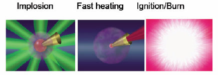
FIGURE 2.1 In this fast ignition approach, a hollow gold cone inserted in the spherical shell is used to couple energy to the compressed core. SOURCE: H. Azechi, Osaka University, “Inertial Fusion Energy: Activities and Plans in Japan,” Presentation to the committee on June 15, 2011.
Radiographic Capability, among others) as well as the most advanced theory and computer simulation capability available.
Laser-Driven Shock Ignition
As in fast ignition, shock ignition separates the compression of the thermonuclear fuel from the ignition trigger. The ignition process is initiated by a spherically convergent strong shock (the “ignitor shock”) launched at the end of the compression pulse. This late shock collides with the return shock driven by the rising pressure inside the central hot spot and enhances the hot-spot pressure.13 Since the ignitor shock is launched when the imploding shell is still cold, the shock propagation occurs through a strongly coupled, dense plasma. If timed correctly, the shock-induced pressure enhancement triggers the ignition of the central hot spot. In laser direct-drive shock ignition, the capsule is a thick wetted-foam shell14,15 driven at a relatively low implosion velocity of ~250 km/s. The compression pulse consists of a shaped laser pulse designed to implode the capsule with low entropy to achieve high volumetric and areal densities. The fuel mass is typically greater for shock ignition than for hot-spot ignition. The large mass of fuel leads to high fusion-energy yields and the low entropy leads to high areal densities and large burn-up fractions. These conditions lead to high predicted gain. The ignitor shock
__________________________
13 R. Betti, C.D. Zhou, K.S. Anderson, L.J. Perkins, W. Theobald, and A.A. Solodov, 2007, Shock ignition of thermonuclear fuel at high areal density, Physical Review Letters 98: 155001.
14 Ibid.
15 J. Sethian and S. Obenschain, Naval Research Laboratory, “Krypton Fluoride Laser Driven Inertial Fusion,” Presentation to the committee on January 29, 2011.
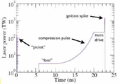
FIGURE 2.2 Shock ignition power input. SOURCE: J. Sethian and S. Obenschain, Naval Research Laboratory, “Krypton Fluoride Laser-Driven Inertial Fusion,” Presentation to the committee on January 29, 2011.
is required because at low velocities the central hot spot is too cold to reach the ignition condition with the conventional ICF approach. The ignitor shock can be launched by a spike in the laser intensity on target or by particle beams incident on the target surface (see Figure 2.2).
Recent numerical simulations suggest that it may be possible to achieve gains exceeding 100 at laser energies smaller than 500 kJ.16 Although the intensity of the final shock ignition pulse exceeds the threshold for laser–plasma instabilities, there are grounds to believe that target preheat by fast electrons may not be a problem.17
Laser Beam–Target Interaction
In order to achieve any of the conditions needed for ignition and thermonuclear burn, it is essential that the beams interact properly with the target. For
__________________________
16 A.J. Schmitt, J.W. Bates, S.P. Obenschain, S.T. Zalasek, and D.E. Fyfe, 2010, Shock ignition target design for inertial fusion energy, Physics of Plasmas 17: 042701.
17 Ibid.
example, if too large a fraction of the beam energy is reflected or refracted away from the target, it is not possible to achieve high energy gain. Also, as noted above, the beam–target interaction must not produce a sufficient number of energetic electrons or photons to preheat the fuel so that it cannot be adequately compressed. For indirect drive, the beam energy must efficiently convert into X-rays, and for direct drive, the ablation process must efficiently drive the implosion. Despite extensive theoretical and experimental work, beam-target interactions are still not fully understood. The beam-target interaction for ion beams will be discussed in a later section. For laser beams, effects such as laser–plasma instabilities depend on the size of the plasma. While there is considerable experimental information at scale sizes that are too small to achieve ignition and burn, these instabilities are an important concern for both direct drive and indirect drive for fusion-scale targets, especially because the available experimental data are limited. Furthermore, the instabilities become more deleterious with increasing wavelength and increasing laser intensity. The scaling with wavelength is the reason that current target experiments are usually performed with frequency-tripled 351 nm light from solid-state lasers or the 248 nm ultraviolet light from KrF lasers. The intensity scaling means that laser–plasma instabilities are greater during the brief shock-ignition pulse than during hot-spot ignition, although hot-spot ignition may be more vulnerable to the hot electrons produced by laser–plasma instabilities over the long drive pulse. OMEGA, Nike, and the NIF are valuable national assets that are continuing to elucidate the unknown features of laser–plasma interactions.
Status of Laser-Driven Target Implosion Research
The NIF laser, commissioned in March 2009, is a unique facility for exploring IFE physics and validating target design and performance. It is the only facility that may be able to demonstrate laser-driven ignition during the next several years. It can deliver up to ~1.8 MJ of UV (351 nm) energy with 30-ps timing precision. The NIF laser has met a 95 percent availability level for requested shots, and more than 300 shots were commissioned through 2012. Critical ignition physics studies took place during the National Ignition Campaign (NIC) program, which concluded on September 30, 2012. The goal of this program was to achieve ignition, to commission targets, and to understand the physics necessary for successful, reliable ignition. Recent target shots have led to improved symmetry and a measured yield of 5-9 × 10¹⁴ neutrons at 1.4-1.6 MJ drive energy. To put this in perspective, alpha particle heating of dense fuel surrounding the hot spot is confirmed at a yield of ~1016 neutrons and breakeven ignition at ~5.6 × 10¹⁷ neutrons on a threshold curve
calculated to be very steep.18 The NIC made progress in approaching the sphericity, compression, and velocity needed for ignition. However, the NIC experiments produced a number of surprising results, particularly a lower-than-expected implosion velocity. There are also still uncertainties associated with low-mode asymmetries of the dense fuel and mix.
In its conclusion, the Target Panel (see Appendix H for the summary of its report) says that “based on its analysis of the gaps in current understanding of target physics and the remaining disparities between simulations and experimental results … ignition using laser indirect drive is not likely in the next several years.”19 In the same place, it also states that “resolving the present issues and addressing any new challenges that might arise are likely to push the timetable for ignition to 2013-2014 or beyond.” The panel goes on to also conclude as follows:
- If ignition is achieved with indirect drive at NIF, then an energy gain of 50-100 should be possible at a future facility. How high the gain at NIF could be will be better understood by follow-on experiments once ignition is demonstrated. At this writing, there are too many unknowns to project a potential gain. (Conclusion 4-3)
- Achieving ignition will validate assumptions underlying theoretical predictions and simulations. This may allow a better appreciation of the sensitivities to parameters important to ignition. (Conclusion 4-3)
- The NIF has the potential to support the development and further validation of physics and engineering models relevant to several IFE concepts, from indirect-drive hohlraum designs to polar direct-drive ICF and shock ignition. (Overarching Conclusion 1)
- The NIF will also be helpful in evaluating indirectly driven, heavy-ion targets. It will be less helpful in gathering information relevant to current Z-pinch, heavy-ion direct drive, and heavy-ion advanced target concepts.
As noted above, the NIC was completed on September 30, 2012. With input from the ICF laboratories, the National Nuclear Security Administration (NNSA) produced a report that put forward a “Plan B” experimental program for FY2013 and beyond.20 These issues and tentative plans were discussed in presentations to the committee.21
Conclusion 2-1: There has been good technical progress during the past year in the ignition campaign carried out on the National Ignition Facility.
__________________________
18 E.I. Moses, 2011, The National Ignition Facility and the promise of inertial fusion energy, Fusion Science and Technology 60: 11-16.
19 NRC, 2013, Assessment of Inertial Confinement Fusion Targets, Washington, D.C.: The National Academies Press, released as a prepublication (Target Panel Report).
20 National Nuclear Security Administration, 2012, NNSA’s Path Forward to Achieving Ignition in the Inertial Confinement Fusion Program: Report to Congress, December.
21 J. Quintenz, NNSA, and M. Dunne, LLNL, Two presentations to the committee on February 22, 2012 (see Appendix C).
Nevertheless, ignition has been more difficult than anticipated and was not achieved in the National Ignition Campaign, which ended on September 30, 2012. The results of experiments to date are not fully understood. It will likely take significantly more than a year to gain a full understanding of the discrepancies between theory and experiment and to make modifications needed to optimize target performance.
The NIF is currently a unique tool for addressing these issues, some of which could be addressed with NIF in its present configuration. Others may require modifications such as improvements in beam smoothness or, ultimately, even a different illumination geometry.
Laser–plasma instabilities (LPI) are present in current NIF indirect-drive experiments as well as in the most energetic spherical direct drive (SDD) experiments performed on OMEGA. Robust, high-gain, laser inertial fusion target design must address and contain the effects of these nonlinear processes, which have an intensity threshold behavior that in principle makes modeling extrapolation from low gain to high gain problematic. Both OMEGA (glass laser) and Nike (KrF laser) can test different ablator materials with respect to laser–plasma instabilities. Following the recent results from OMEGA experiments,22 ablators with moderate atomic number (from carbon to silicon) greatly reduce LPI while preserving good hydrodynamic properties. OMEGA and Nike can also compare the acceleration of flat foils at the different wavelengths of 351 nm (OMEGA) and 249 nm (Nike), with different bandwidths or beam smoothing, to determine whether there is a significant advantage to using shorter-wavelength, higher-bandwidth KrF illumination for direct drive. Options to continue the work are discussed in the subsection Laser Drivers, below.
Recommendation 2-1: The target physics programs on the NIF, Nike, OMEGA, and Z should receive continued high priority. The program on NIF should be expanded to include direct drive and alternate modes of ignition. It should aim for ignition with moderate gain and comprehensive scientific understanding leading to codes with predictive capabilities for a broad range of IFE targets.
Ion Beam Targets
In many respects, ion beam targets are similar to the laser targets that have just been discussed. Ion range (penetration depth) is roughly the analog of laser
__________________________
22 V. Smalyuk, R. Betti, J.A. Delettrez, V. Yu, et al., 2010, Implosion experiments using glass ablators for direct-drive inertial confinement fusion, Physical Review Letters 104: 165002.
wavelength. Ion range is a function of ion mass and ion kinetic energy. The range decreases with increasing mass and increases with increasing kinetic energy. Light ions (e.g., Li) have the appropriate range to drive targets at a kinetic energy on the order of 30 MeV. Heavier ions such as Cs or Pb have the appropriate range at energies in the multi-GeV range. It is usually easier to focus ions at higher kinetic energy and higher mass, so most of the emphasis is currently on heavy-ion fusion as opposed to light-ion fusion. Nevertheless, the comments in this section apply to both.
For ion indirect drive, the fuel capsule (the ablator and fuel) is essentially the same as the fuel capsule for laser indirect drive. The primary difference lies in the physics of the beam-target interaction and conversion of beam energy into radiation. Thus, experience with laser indirect drive on the NIF will put to rest many of the issues associated with ion indirect drive.23 In this regard, it important to note that target simulations for both driver options are performed using the same computer codes. From a fuel-capsule standpoint, the status and issues are the same as those discussed above for laser indirect drive. The principal new questions are these:
- Can one correctly predict the range of intense ion beams in hot matter?
- Are there processes that can produce unacceptable levels of preheat?
- What is the efficiency of converting beam energy into radiation?
Ion range has been studied for nearly a century. The theory is relatively straightforward, and the agreement between theory and experiment is good for low- intensity ion beams in cold matter. In particular, numerous ion deposition experiments have been performed in the kinetic energy range of interest for both light-ion and heavy-ion fusion. The range of intense ion beams in hot matter is the question. Some experiments have been performed in preheated plasmas to simulate the conditions appropriate for inertial fusion, and light-ion beams have been used to heat material to 58 eV, at temperatures within a factor of ~3 of that needed for inertial fusion.24 The theoretical uncertainties in ion range in hot matter appear to have little relevance for indirectly driven targets, since the beam energy, the target material(s), and the wall thickness can be adjusted when the details of ion-beam-matter interaction are actually measured.
There have also been extensive theoretical and numerical searches for processes that might produce unacceptable preheat.25 No such processes have been found.
__________________________
23 J.D. Lindl, P. Amendt, R.L. Berger, S.G. Glendinning, et al., 2004, The physics basis for ignition using indirect-drive targets on the National Ignition Facility, Physics of Plasmas 11(2): 339.
24 Ibid.
25 D.W. Hewett, W.L. Kruer, and R.O. Bangerter, 1991, Corona plasma instabilities in heavy-ion fusion targets, Nuclear Fusion 31(3): 431 and references therein.
Also, numerical simulations predict high conversion efficiency of ion-beam energy into radiation.
In summary, calculations and limited experimental information are promising for ion-beam indirect drive. Numerical simulations predict gains as high as 130 at 3 MJ, but experiments with more intense beams are required to augment the information on indirect-drive target performance being produced at the NIF.
For lasers, it is appropriate to make a sharp distinction between direct drive and indirect drive. For ion beams, the distinction is not as sharp. There are targets that are fully directly driven or fully indirectly driven, but there are also targets that lie between the two extremes. Calculations indicate that the targets at the direct end of the spectrum can produce high gain at low driver energy.26 Unfortunately, the ion range needed for pure direct drive is sufficiently small that it has proved very difficult to design an accelerator that can meet the focusing requirements. This situation has led to the study of targets that are similar to directly driven targets except that the outer shell of the target, outside the ablator, is made of a dense, high-Z material. Early in time, the pressure to drive the implosion is almost completely generated by direct ion deposition, i.e., by direct drive. Later in the pulse, radiation becomes an important energy transport mechanism and the dense shell acts like a hohlraum. Calculations indicate that these targets can also produce high gain at low driver energy. Moreover, the gain is relatively insensitive to ion range, and the ion range is comparable to that required by indirect drive. These “mixed” targets are often referred to as directly driven targets, although the physics of the implosion and issues of stability are very different from those used in laser direct drive.
Currently there are ongoing numerical simulations involving direct drive with hot-spot ignition and shock ignition. Both spherical and polar illumination geometries are being considered. As is the case for lasers, the predicted target gain is higher for direct drive than for indirect drive. Unfortunately, there is no experimental information on ion direct drive.
Ion-Driven Fast Ignition
The earliest targets for heavy-ion fusion, described in the mid-1970s, were based on fast ignition using intense ion beams.27 Imploding the fuel using ion beams and igniting it with a laser is another option. Current research favors the original approach, which uses ion beams for both processes. In principle, one should be able to achieve high gain from such targets. Also, the ignition physics appears to be more straightforward than laser fast-ignition physics, but the ion kinetic energy
__________________________
26 B.G. Logan, LBNL, “Heavy Ion Fusion,” Presentation to the committee on January 29, 2011.
27 A.W. Maschke, 1975, Relativistic ions for fusion applications, Proceedings of the 1975 Particle Accelerator Conference, Washington, D.C., IEEE Transactions on Nuclear Science, NS-22(3): 1825.
required to obtain the required small focal spots is an order of magnitude or more larger than the kinetic energy required for direct drive or indirect drive. Although the ignition physics appears to be straightforward, some important parts of this physics have not yet been incorporated into the codes used for numerical simulation. Furthermore, there are important uncertainties in focusing physics, target physics, and accelerator design that have not been adequately addressed. If these uncertainties can be resolved favorably using theory and simulation, there is still a programmatic issue. The accelerator needed to drive fast ignition targets is not the accelerator needed to drive the other types of targets. In other words, to obtain definitive experimental information on this option, one would have to build a unique accelerator with a far shorter pulse length. The challenges for this approach are to address the uncertainties, establish its superiority over other approaches, and develop a strong enough case to build a unique accelerator.
It is noteworthy that both U.S. and foreign heavy-ion fusion programs are studying targets based on ion fast ignition. The U.S. version of such targets is referred to as the X-target (see Figure 2-6 in the Target Panel report). The X-target design has evolved rapidly during the last year but has not been fully evaluated.
Pulsed-Power Targets
Historically, both indirect drive and ion- and electron-driven direct drive have been studied for pulsed-power inertial fusion. Many of the considerations discussed above for laser and heavy-ion targets also apply to these classes of pulsed-power targets. Magnetic implosion offers the possibility of significantly higher implosion efficiency than the other approaches, and it is currently the favored option. The targets being considered for Magnetized Liner Inertial Fusion at present are beryllium (conducting) cylinders that contain the fusion fuel at high pressure. As the magnetically driven implosion of the cylinder is initiated, a laser preionizes and preheats the gaseous fuel, which is then compressed and heated to ignition by the imploding metal cylinder in less than 100 ns (see Figure 2.3). The codes used to design these targets have not yet been experimentally validated.28
In the case of Magnetized Target Fusion (MTF), a field-reversed-configuration plasma is compressed by an imploding metal cylinder on a timescale of a few microseconds.29
__________________________
28 M. Cuneo et al., Sandia National Laboratories, “Pulsed Power IFE: Background, Phased R&D and Roadmap,” Presentation to the committee on April 1, 2011.
29 G. Wurden and I. Lindemuth, “Magneto-Inertial Fusion (Magnetized Target Fusion),” Presentation to the committee on March 31, 2011.
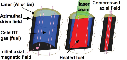
FIGURE 2.3 The magnetized liner fusion target. SOURCE: M. Cuneo, Sandia National Laboratories, Presentation to the committee on April 1, 2011.
DRIVER OPTIONS FOR INERTIAL CONFINEMENT FUSION
This section provides a description of each driver type being considered for IFE. Each driver description begins with background and status of the driver technical application and then goes on to the scientific challenges and future research and development priorities, including a description of the path forward in the near, medium, and long term for each driver type.
As noted in the preceding section, the technical approaches to achieving inertial fusion energy include three kinds of drivers: lasers, heavy-ion accelerators, and electrical pulsed-power systems. As discussed below, good progress has been made in developing the repetitively pulsed systems required for fusion energy. Nevertheless, for all types of drivers, there remain substantial challenges in developing systems that would have the quality, reliability, maintainability, and availability to provide a number of shots that, depending on the driver, range from 3 × 10⁶ to 4 × 10⁸ per year. For each technological approach, the committee identifies a series of critical R&D objectives that must be met for that approach to be viable. If these objectives cannot be met, then other approaches will need to be considered.
Laser Drivers
Two types of laser drivers have been considered as possible candidates for IFE: the solid-state laser and the krypton fluoride (KrF) gas laser. The first part
of this section describes progress in solid-state laser technology. The second part describes the background and progress in KrF ultraviolet gas laser for fusion-driver applications.
All lasers require a gain medium, a pump source, and an optical resonator system to shape and extract the laser power. Since the demonstration of the lamp-pumped, ruby laser in 1960, enormous progress has been made in the gain media, pumping sources, operating efficiency, and average power of lasers. A recently published handbook provides an overview of the status of high-power lasers, including chapters on the NIF laser, the KrF laser, and on high-power diode arrays for pumping high-average-power, solid-state lasers.30
Projected Target Gains
Ignition and gain with indirect drive are presently being pursued in the NIF, following decades of research on earlier laser systems such as Nova.31 Computations at LLNL suggest that in a power plant, reactor-scale target gains of ≥60 might be attainable with optimized indirect-drive targets driven by 2 MJ of 3ω32 light.33
Direct-drive targets are also being considered. Their designs evolved from work at the University of Rochester’s LLE and the Naval Research Laboratory (NRL) during the 25 years from 1985 to 2010, taking advantage of the new smoothing techniques and tailored adiabats. In one-dimensional calculations, a reactor-scale target gain of 150 with only 400 kJ input has been projected when a 248-nm KrF wavelength is used with shock ignition; the calculated target gain vs. laser drive energy is shown in Figure 2.4.
Diode-Pumped Solid-State Lasers
Background and Status
Early solid-state lasers were pumped by spectrally broad flashlamps, from which only a small fraction of light was absorbed by the laser ions, leading to operating efficiencies in the range of 1-2 percent. The trend in commercial lasers is to replace lamp-pumped, solid-state lasers with diode-pumped, solid-state
__________________________
30 H. Injeyan and G.D. Goodno, 2011, High-Power Laser Handbook, New York, N.Y.: McGraw Hill.
31 Nova is the 100 kJ, flashlamp-pumped laser that preceded the NIF at Lawrence Livermore National Laboratory.
32 That is, three times the fundamental frequency of the laser, or 351 nm wavelength.
33 M. Dunne, LLNL, “Update on NIF, NIC and LIFE,” Presentation to the committee on February 22, 2012.
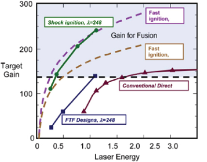
FIGURE 2.4 Target gain curves from one-dimensional simulations of various high-performance direct-drive target designs. The horizontal axis is in megajoules. The shaded region shows sufficient target gain for the power plant with KrF laser drive (G = 140). A gain G = 60 is shown as sufficient for a diode-pumped, solid-state laser (DPSSL) drive. Triangles are the calculated gain for a conservative conventional direct drive target, for either KrF or DPSSL (300 km/s implosion velocity). Squares are the Fusion Test Facility designs for KrF (λ = 248 nm) and higher ablation pressure implosion velocity of 350-450 m/s. Circles are for shock-ignition targets for KrF: soft conventional compression (<300 km/s) and then spike to shock heat to ignition. Dashed lines are fast ignition scaling for KrF (248 nm) and DPSSL (351 nm). Both fast ignition and shock ignition calculated gain curves are considered to be optimistic because so little is known about implementation. SOURCE: Adapted from J. Sethian, D.G. Colombant, J.L. Giuliani, et al., 2010, The science and technologies for fusion energy with lasers and direct-drive targets, IEEE Transactions on Plasma Science 38: 690.
lasers (DPSSLs) to improve operational efficiency and reliability for demanding 24/7 industrial applications.
An example solid-state laser consists of a diode laser tuned to 808 nm to match the absorption line of the neodymium (Nd) ion doped into a yttrium–aluminum– garnet (YAG) crystal. A lens focuses the diode output into the Nd:YAG crystal, and
a resonator around the Nd:YAG crystal tuned to 1064 nm forms the oscillator.34 To obtain higher power, the design is extended to the “master oscillator, power amplifier” configuration, where the low-power, well-controlled laser oscillator output is amplified by a power amplifier, as the name suggests. Today, solid-state lasers are commercially available with power levels ranging from ~1 W to 10 kW, and they operate with very high reliability to support manufacturing processes.
The scale of the laser energy required for an indirect-drive or direct-drive IFE power plant is likely to be comparable to the NIF laser—i.e., ~2 MJ per pulse in the ultraviolet but operated at 5 to 15 pulses per second repetition rate. Although a DPSSL driver can be used to drive either direct-drive or indirect-drive targets, this section describes a DPSSL-driven IFE power plant based on indirect drive because that approach is more mature and has been studied in the NIF-driven target experiments in depth. A KrF laser direct-drive approach is also discussed below. If direct drive proves to offer lower thresholds for ignition, as predicted by theory but not confirmed by experiments to date, then the DPSSL laser can be engineered to drive polar- or spherical-direct-drive targets.35 For simplicity, in the remainder of the DPSSL section the term “laser” or “solid-state laser” will be used to mean “diode-pumped solid-state laser.”
While the NIF laser was designed for single-shot operation for target physics and ignition studies, an IFE laser driver must operate at 5 to 15 shots per second for extended periods of time at high efficiency. As such, an IFE solid-state laser driver cannot be flashlamp-pumped, as is the NIF laser. For example, one proposed laser-driven, IFE power plant design, the laser inertial fusion energy (LIFE) design,36 proposes to use DPSSLs and a modular architecture approach, as illustrated in Figure 2.5.
Laser system designs, based on extensive experimental measurements, show that advanced phosphate glass (APG) can operate at a 10-20 Hz repetition rate when diode-laser pumped at a safety margin of one-third the stress fracture limit.37 Improvements in diode laser efficiency, diode laser-array irradiance, and coupling efficiency have allowed the projected electrical efficiency of solid-state IFE drivers to increase from 8.5 percent in 1996 to about 15 percent wall-plug efficiency (cooling taken into account) in the UV in a present-day energy-storage laser design.38
__________________________
34 R.L. Byer, 1988, Diode laser-pumped solid-state lasers, Science 239: 742-747.
35 J. Quintenz, NNSA, “Status of the National Ignition Campaign & Plans Post-FY 2012,” Presentation to the committee on February 22, 2012.
36 T.M. Anklam, M. Dunne, W.R. Meier, S. Powers, and A.J. Simon, 2011, LIFE: The case for early commercialization of fusion energy, Fusion Science and Technology 60: 66-71; see also T. Anklam, LLNL, “LIFE Economics and Delivery Pathway,” Presentation to the committee on January 29, 2011.
37 A. Bayramian, S. Aceves, T. Anklam, et al., 2011, Compact, efficient laser systems required for laser inertial fusion energy, Fusion Science and Technology 60: 28-48.
38 Ibid.
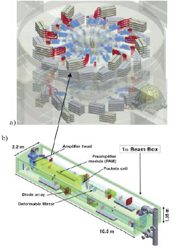
FIGURE 2.5 (a) Isometric view of a proposed laser-driven IFE power plant showing compact beam architecture composed of 384 lasers. (b) Isometric expanded view showing the contents of one ~100 kW solid-state laser in a beam box. SOURCE: J. Latkowski, LLNL, private communication to the committee, December 23, 2011.
As an example of average power and efficiency, a continuous-wave, diode-laser-pumped Nd:YAG laser, with more efficient power extraction than the pulsed laser for IFE, demonstrated greater than 19 percent wall plug efficiency in 2009 in a near-diffraction-limited beam at a 105 kW average power.39
The modular architecture provides flexibility in laser operation. For example, the laser can be configured to generate high-intensity green (frequency doubled) light at 532 nm. Green light often is associated with greater laser–plasma interaction (LPI) but offers the potential to assemble larger targets for higher gain. Further, the laser can generate output in the deep UV (4ω) at 263 nm for plasma studies or direct-drive studies. Recent work demonstrated near-room-temperature frequency doubling in a deuterated potassium dihydrogen phosphate (KDP) nonlinear crystal with 79 percent efficiency from a green Nd:glass laser to the deep UV at 263 nm.40 This was achieved in a single-shot second harmonic generation experiment of the green 526 nm to generate UV at 263 nm at an intensity of 1 GW/cm2 from a 3 ns, 4 J green pulse.
According to presentations to the committee, the global market for solid-state lasers has increased more than 15 percent per year, a pace that has facilitated mass production of laser diodes in a very competitive market served by many suppliers.41 Commercial markets have driven continuous improvements in the performance and efficiency of laser diodes for pumping solid-state lasers. The size and the growth of the commercial markets underpin the projection of cost and performance of diode laser arrays for pumping future IFE solid-state laser drivers. Of particular interest are the projected lifetimes of large diode laser arrays for pumping an IFE laser driver. Based on recent measurements, the operational lifetimes are projected to be greater than 13.5 billion shots, or greater than 100,000 hours at a 37 Hz repetition rate.42
The semiconductor diode laser array manufacturers prepared a white paper stating that they can meet the projected costs and performance requirements for diode laser arrays for pumping solid state lasers for IFE.43 This white paper
__________________________
39 J. Marmo, H. Injeyan, H. Komine, S. McNaught, J. Machan, and J. Sollee, 2009, Joint high power solid state laser program advancements at Northrop Grumman, SPIE Proceedings 7195: 719507.
40 S.T. Yang, T. Steven, M.A. Henesian, T.L. Weiland, et al., 2011, Noncritically phase-matched fourth harmonic generation of Nd:glass laser in partially deuterated KDP crystals, Optics Letters 36: 1824.
41 A.J. Bayramian, S. Aceves, T. Anklam, et al., 2011, “Compact, efficient laser systems required for laser inertial fusion energy,” Fusion Science and Technology 60: 28-48. and R. Deri, J. Geske, M. Kanskar, S. Patterson, G. Kim, Q. Hartmann, F. Leibreich, E. Deichsel, J. Ungar, P. Thiagarajan, R. Martinsen, P. Leisher, E. Stephens, J. Harrison, C. Ghosh, O. Rabot, A. Kohl, “Semiconductor Laser Diode Pumps for Inertial Fusion Energy Lasers,” Lawrence Livermore National Laboratory, LLNL-TR-465931, January 2011.
42 R. Feeler, J. Junghans, J. Remley, D. Schnurbusch, and E. Stephens, 2010, Reliability of high-power QCW arrays, Proceedings of SPIE 7583.
43 R. Deri et al., op. cit.
estimates a cost reduction to 0.7 cents per watt of diode laser light for an nth-of-a-kind IFE plant to be possible.44
An estimate of the cost of diode laser arrays versus the production volume has been made by engineers in Japan.45 The projected costs, based on past and current diode laser costs, are $0.03/peak-watt at production volume of 100 million bars per year. This cost estimate appears to be consistent with that made at LLNL in their projections of diode laser costs.46
Table 2.1 describes the proposed design for an IFE driver operating in the UV at 351 nm with 2.2 MJ total energy and comprised of 384 lasers in a box. The top-level IFE laser driver system requirements are 2.2 MJ in the UV (351 nm) operating at 16 Hz repetition rate for an average laser power of 35 MW at 18 percent electrical efficiency (equivalent to 15 percent wall-plug efficiency) in the UV.
Details of the proposed solid-state IFE driver based on neodymium-doped APG are provided in a recent publication.47 A single laser in a box module of the laser driver would operate at 130 kW (IR)/91 kW (UV) average power and 8.1 kJ (IR)/5.7 kJ (UV) output pulse energy at 16 Hz repetition rate. The aperture size is 25 × 25 cm and the operating UV wall-plug efficiency is 15 percent. The laser design would use a series of well-known features such as polarization rotation for birefringence compensation, flowing helium gas for cooling of the 20 graded-doped, 1-cm-thick APG glass gain elements in each of the two gain modules, and polarization combining of the diode laser pump arrays to double pump irradiance. The projected 75 percent harmonic conversion efficiency to the UV is obtained by optimizing harmonic conversion in separate channels for the foot and the peak of the laser pulse shape. Finally, the proposed modular architecture for the laser has a built-in 15 percent operating margin, such that the fusion plant could continue to operate even with the shutdown of a beam line for replacement or repair. The proposed laser-in-a-box modules illustrated in Figure 2.5 have been designed to be shipped by truck from the factory to the IFE plant site and to be hot-swapped while the plant continues to operate.
The modular architecture approach is essential to achieving a high operational availability for the DPSSL IFE plant. It would allow upgrades and improvements to the laser driver modules without the need for shutting down plant operation. The modular architecture would enable an IFE plant to follow an upgrade path starting with a lower plant power output and increasing plant output over time by adding banks of laser modules.
__________________________
44 R. Deri et al., op. cit.
45 H. Azechi, Osaka University, “Inertial Fusion Energy: Activities and Plans in Japan,” Presentation to the committee on June 15, 2011.
46 R. Deri et al., op. cit.
47 A. Bayramian, S. Aceves, T. Anklam, et al., 2011, Compact, efficient laser systems required for laser inertial fusion energy, Fusion Science and Technology 60: 28-48.
TABLE 2.1 Laser System Requirements for a Diode Laser-Pumped Solid-State IFE Driver Operating in the UV at 351 nm
|
|
|
| Characteristic | Requirement |
|
|
|
| Total laser energy at 351 nm (MJ) | 2.2 |
| Total peak power (TW) | 633 |
| No. of beam lines | 384 (48 × 8) |
| Energy per beam line at 351 nm (kJ) | 5.4 |
| Wall plug efficiency at 351 nm (%) | 15 |
| Repetition rate (Hz) | 16 |
| Lifetime of system (shots) | 30 × 109 |
| Availability | 0.99 |
| Maintenance (h) | <8 |
| Beam pointing (μm root-mean-square) | 100 |
| Beam group energy stability (8 beams) (% root-mean-square) | <4 |
| Beam-to-beam timing at target (ps root-mean-square) | <30 |
| Focal spot (w/CCPa), 95% enclose (mm) | 3.1 |
| Spectral bandwidth, 3ω (GHz)b | 180 |
| Prepulse at 20 ns prior to main pulse (W/cm2) | <108 |
|
|
|
| a CPP, Continuous Phase Plate, is used to modify the far field from a peak to a flat top for target drive. b Used for suppression of stimulated Raman scattering, stimulated Brillouin scattering, and in conjunction with a diffraction grating for smoothing by spectral dispersion (SSD) of the laser speckle induced by the use of the CPP on target. SOURCE: A. Bayramian, S. Aceves, T. Anklam, et al., 2011, Compact, efficient laser systems required for laser inertial fusion energy, Fusion Science and Technology 60: 28-48. |
|
The Global R&D Effort on Solid-State Lasers for IFE Drivers
The laser driver for IFE is a significant component (~25 percent) of the capital cost of an IFE plant and is therefore the subject of research and development aimed at maximizing the performance, availability, and reliability of DPSSL driver for IFE in Europe,48 Japan,49 China,50 and the United States.
In France, the construction of the Laser MégaJoule (LMJ) project, a NIF-like, flashlamp-pumped Nd:glass laser system with a goal of 2 MJ drive energy,51 is
__________________________
48 J. Collier, Ruther Appleton Laboratory, “Recent Activities and Plans in the EU and UK on Inertial Fusion Energy,” Presentation to the committee on June 15, 2011.
49 H. Azechi, Osaka University, “Inertial Fusion Energy: Activities and Plans in Japan,” Presentation to the committee on June 15, 2011.
50 J. Zhang, Institute of Physics, Chinese Academy of Sciences, and Xiantu He, Beijing Institute of Applied Physics and Computational Mathematics, “Inertial Fusion Energy: Activities and Plans in China,” Presentation to the committee on June 15, 2011.
51 J. Collier, Ruther Appleton Laboratory, “Recent Activities and Plans in the EU and UK on Inertial Fusion Energy,” Presentation to the committee on June 15, 2011, and R. Garwin and D. Hammer, “Notes from Our LMJ Visit, February 26, 2011,” Presentation to the committee on March 30, 2011.
nearing completion. This large, single-shot laser system is designed for physics and target studies. Recently, Russia announced its plans for ISKRA/UFL, a nearly 3 MJ fusion laser.
R&D in Europe and Japan is directed toward diode-pumped, cryo-cooled, Yb:YAG ceramic lasers. Cryocooling of Yb:YAG brings improved performance and optimum gain and power extraction.52 Modern transparent laser ceramics were developed in Japan beginning in 1995.53 Lasers based on ceramics were shown to perform as well as, or better than, single crystal lasers.54 Today, ceramic laser gain media are available in the size 10 cm × 10 cm. Laser ceramics are still undergoing extensive research to improve the quality and consistency of the material. In the future, when commercial supplies of ceramic laser gain materials are available, ceramics may replace glass as the preferred laser host material in high-average-power IFE laser drivers. When laser ceramics do become available, the modular architecture of the proposed laser IFE driver may be able to accommodate the new gain media without making major changes to the IFE system.
In China, the development of IFE laser drivers is based on lamp-pumped Nd:glass lasers. The next step is to bring online by 2012-2013 the Shenguang (Divine Light) SG-III laser, which will operate frequency-tripled (like the NIF) at 351 nm for inertial confinement fusion experiments with 48 beams at 3 ns and 200 kJ total energy. The longer-range plan is to construct and operate the NIF-scale SG-IV laser by 2020 at 3 ns and 1.5 MJ (351 nm). Work has also been initiated in China on diode-pumped, cryocooled, solid-state lasers for future IFE drivers.
Scientific and Engineering Challenges and Future R&D Priorities for DPSSLs for IFE Applications
The following proposed DPSSL R&D program, as described in presentations to the committee, illustrates the key technical challenges that should be addressed to mitigate risks going forward:
- Pulsed diode laser drivers and diode laser arrays with polarization combining. Research on the optimized design of pulse diode laser bars and arrays of bars should be pursued to optimize diode bar efficiency and power per bar and facilitate lower production costs.
__________________________
52 T.Y. Fan, 2007, Cryogenic Yb3+-doped solid state lasers, IEEE Journal of Quantum Electronics13: 448.
53 A. Ikesue, Y.L. Aung, T. Taira, T. Kamimura, K. Yoshida, and G.L. Messing, 2006, Progress in ceramic lasers, Annual Review of Materials Research 36: 397-429.
54 K. Ueda, J.F. Bisson, H. Yagi, K. Takaichi, A. Shirakawa, T. Yanagitani, and A.A. Kaminskii, 2005, Scalable ceramic lasers, Laser Physics 15 : 927-938.
- Birefringence compensation by polarization rotation and balanced gain module pumping. The idea of birefringence compensation by use of polarization rotation and balanced thermal loading of two gain elements is well known. Polarization rotation should be experimentally tested to determine whether specifications can be met at 15 Hz and ~130 kW average power in the IR from a laser in a box.
- The KD*P switch for optical isolation and four pass oscillator/amplifier control.55 The KD*P polarization switch is placed in the low optical fluence zone of the laser system. However, the KD*P must be cooled and the appropriate 20 kV electric field applied for switching. The operation of this switch should be tested to validate modeling and assure proper operation under repetition rate and thermal loading.
- Efficiency and thermal cooling of the KD*P harmonic generation converter. The KD*P nonlinear frequency converter operates at average power and is cooled with flowing helium gas. The conversion efficiency of the convertor and the operation at average power should be determined by testing at full average power.
- UV beam line damage testing and beam delivery utilizing the fused silica Fresnel lens at 580°C. The UV beam line is a critical element in the delivery of the laser power to the chamber and through the Fresnel lens to a focus at the target position. Optical damage testing should be done to assure reliable operation of the final fused silica Fresnel lens optic at operating temperature and optical fluence.
- The laser beam-line-in-a-box should be modeled and tested at full scale. The laser in a box is a critical element and should be tested at full scale and at operating conditions to determine if it can meet design reliability, power, pointing, and vibration and alignment requirements. It should be tested to determine that it can meet the hot-swap requirements for a line-replaceable unit.
Path Forward for Diode-Pumped Solid-State Laser-Based Inertial Fusion Energy
In this section, the integrated systems engineering and supporting R&D required to develop a solid-state, laser-driven IFE power plant is described. This plan for DPSSL drivers is based on the LIFE team’s submissions to the committee and other publications.
LIFE is based on indirect-drive targets injected into a xenon-gas-filled chamber, as described in the LIFE design study. The advantages of the gas-filled chamber were
__________________________
55 KD*P is potassium dideuterium phosphate, a material used widely in frequency conversion optics.
described to the committee by Wayne Meier.56 This reactor would be made of steel with a 6-m-diameter chamber comprising segmented and replaceable chamber walls. The chamber is located within the vacuum walls and is designed to be replaced periodically. The use of xenon gas reduces peak temperature spikes at the chamber walls. The 384 laser beams are focused into the indirect-drive target hohlraum through thin, heated SiO2 Fresnel lenses protected from ion bombardment by the xenon gas. The final optics are thin to allow them to slide in and out easily during replacement and are heated to 580°C to provide self-annealing in the radiation environment. The laser propagation through the xenon gas is calculated to be acceptable at the 351 nm drive wavelength.
The R&D program must support the integrated systems engineering approach that is essential for designing a power plant facility that meets customer needs at a cost that is competitive with other sources of energy such a modern fission reactors.57 Issues for which R&D is critical include target physics, design and cost, and survival of the target during injection and engagement at more than 1 million targets per day. Also of interest are recycling of the lead used for the hohlraum, as well as tritium breeding and control—all in addition to the development of reliable, efficient laser drivers.
Near-Term R&D Objectives (≤5 Years)
The proposed Nd-doped APG glass DPSSL driver is based on performance metrics provided by NIF, the Mercury laser system, and commercial laser performance specifications. Prudent engineering practice requires a risk-reduction program to confirm the anticipated performance of the proposed IFE laser driver design. A high-priority, near-term R&D objective is to design, build and test a full-scale laser beam-line module.58 This single laser beam line should achieve all design specifications, including the specifications necessary for a laser line-replaceable-unit that enables a hot-swap exchange in an IFE plant environment.
The laser beam-line module demonstration would allow full-aperture and average-power testing of pulsed laser diode drivers and laser diode arrays with polarization combining. Research is needed to facilitate optimization of pulsed diode bars and arrays of bars to optimize diode bar efficiency and power per bar and to facilitate lower production costs.
__________________________
56 W. Meier, LLNL, “Overview of Chamber and Power Plant Designs for IFE,” Presentation to the committee on January 29, 2011.
57 T.M. Anklam, M. Dunne, W.R. Meier, S. Powers, and A.J. Simon, 2011, LIFE: The case for early commercialization of fusion energy, Fusion Science and Technology 60: 66-71.
58 A. Bayramian, S. Aceves, T. Anklam, et al., 2011, Compact, efficient laser systems required for laser inertial fusion energy, Fusion Science and Technology 60: 28-48.
The UV beam line is a critical element for delivery of the laser power to the chamber and to the target through the fused-silica, Fresnel-lens, final optic. The final optics beam line and optical components should be tested to the limits available to confirm expected lifetimes and performance.
Conclusion 2-2: If the diode-pumped, solid-state laser technical approach is selected for the roadmap development path, the demonstration of a diode-pumped, solid-state laser beam-line module and line-replaceable-unit at full scale is a critical step toward laser driver development for IFE.
Conclusion 2-3: Laser beam delivery to the target via a UV beam line, the final optics components, and target tracking and engagement are critical technologies for laser-driven inertial fusion energy.
Medium-Term R&D Objectives (5-15 Years)
Assuming that ignition has been achieved and the full-scale laser beam line has been designed, constructed, tested, and met design criteria, work would begin on implementing the integrated system engineering design for a laser-driven Fusion Test Facility (FTF), a facility to demonstrate repetitive DT target shots and reactor-scale gain, using reactor-scale driver energy. The medium-term R&D objective is to design, build, and operate such a facility.
One proposal from the LIFE team is a solid-state laser-driven FTF that would operate at the 400 MWe scale in bursts of increasing duration. Its goal would be to demonstrate a target gain of 60-70 and plant gain of ~5, consistent with a laser wall-plug efficiency of 15 percent in the UV. This facility size is a trade between capital cost and operational capability that would inform the IFE community about key aspects of plant operation and material issues in the relevant environment. It would require a chamber capable of operating for the required number of tests and a target factory capable of producing and delivering targets at the necessary rate. The most highly leveraged elements of this facility are the target chamber structural material, the target cost, and target gain,59 so that optimization of these elements would be the key objective. The laser driver and its critical components—laser diodes, design for high efficiency, and the APG glass gain medium—are not high on the list of items that lead to a large variance in the cost of electricity.60
__________________________
59 T.M. Anklam, M. Dunne, W.R. Meier, S. Powers, and A.J. Simon, 2011, LIFE: The case for early commercialization of fusion energy, Fusion Science and Technology 60: 66-71.
60 Ibid.
The FTF would be designed such that it could be upgraded to the 1 GWe power output level in the future. The key issues in moving forward are a combination of technical issues and licensing issues associated with the plant operation and integrated facility design.61
The technologies that would be demonstrated at the FTF include:
- Laser system;62
- Integrated facility design;63
- Target production, injection, and engagement;64
- Chamber and blanket design;65
- Thermoelectric plant; and
- Tritium plant.
Success of a laser-driven facility and the projection of the technology to a cost-effective power plant would assure that this technical approach is a candidate for upgrade to the demonstration-scale power plant described in Chapter 4.
Conclusion 2-4: Laser-driven inertial fusion for energy production requires an integrated system engineering approach to optimize the cost and performance of a Fusion Test Facility followed by a demonstration plant.
Long-Term R&D Objectives (<15 Years)
The long-term objectives are to define a path for commercial energy production based on IFE. The goal can be met if the 400 MWe FTF leads to a 1 GWe power plant facility 10 to 15 years following completion of the FTF.
The details of the progression in the design and performance for each stage of the roadmap to the demonstration facility and then to the commercial power plant have been described by Tom Anklam. Table 2-2 (taken from Anklam’s presentation) shows a conceptual roadmap for a commercialization path that has
__________________________
61 W. Meier, LLNL, “Overview of Chamber and Power Plant Designs for IFE,” Presentation to the committee on January 29, 2011.
62 A. Bayramian, S. Aceves, T. Anklam, et al., 2011, Compact, efficient laser systems required for laser inertial fusion energy, Fusion Science and Technology 60: 28-48.
63 M. Dunne, E.I. Moses, P. Amendt, et al., 2011, Timely delivery of laser inertial fusion energy (LIFE), Fusion Science and Technology 60: 19-27.
64 R. Miles, M. Spaeth, K. Manes, et al., 2011, Challenges surrounding the injection and arrival of targets at LIFE fusion chamber center, Fusion Science and Technology 60: 61-65.
65 J.F. Latkowski, R.P. Abbott, S. Aceves, et al., 2011, Chamber design for the laser inertial fusion energy (LIFE) engine, Fusion Science and Technology 60: 54-59.
TABLE 2.2 Conceptual Roadmap for the Commercialization Path for LIFE
|
|
|||
| Design/Performance | LIFE 1 | LIFE 2 | LIFE 3 |
|
|
|||
| Laser energy 3w (MJ) | 1.3 | 2.4 | 2.0 |
| Repetition rate (Hz) | 14.8 | 14.8 | 14.8 |
| Plant electrical gain | 1.3 | 4.4 | 7.0 |
| House power fractiona | 0.77 | 0.25 | 0.16 |
| Thermal-to-electric efficiency (%) | 43 | 48 | 53 |
| First wall materialb | RAFMS | ODS | ODS |
| Radius (m) | 3.7 | 5.6 | 6.2 |
| First wall neutron loading lifetime (full power equivalent) | |||
| (MW/m2) | 1.9 | 4.5 | 4.5 |
| (dpa/yr) | 20 | 50 | 50 |
| (yr) | 0.9 | 4.5 | 4.5 |
| Fusion yield (MJ) | 27 | 147 | 180 |
| Target gain | 21 | 64 | 94 |
| Fusion power (MW) | 400 | 2,200 | 2,660 |
| Availability allocationc (%) | 50 | 92 | 92 |
|
|
|||
a Also known as recirculating power fraction.
b RAFMS is a low-activation ferritic/martensitic steel and ODS is an oxide dispersion strengthened steel.
c The availability allocation is not a bottom-up calculation but is used to set targets for the LIFE subsystems in regard to reliability, replacement time, and redundancy.
SOURCE: T.M. Anklam, LLNL, “LIFE Economics and Delivery Pathway,” Presentation to the committee on January 29, 2011.
been proposed.66 It consists of three stages. The first stage, referred to as LIFE 1, is the 400 MWe facility described above and is based on the 384 laser module design. LIFE 1 is projected to be operational 10 to 15 years following ignition on NIF at a total build cost of between $4 billion and $6 billion. LIFE 1 will provide operational capability similar to a commercial power plant and will provide the fusion environment required for testing materials in the relevant environment. LIFE 1 is designed to allow an upgrade in scale to the 1 GWe demonstration power plant referred to as LIFE 2 in Table 2-2. The learning curve would lead to an improvement in plant performance at a cost similar to the first plant. The third step, referred to as LIFE 3 power plant design, captures the improvements gained from LIFE 2 operation and provides insight into the economics for the commercial power plant operation.
__________________________
66 T.M. Anklam et al., op. cit.
Krypton Fluoride Lasers
Background and Status
The krypton fluoride laser is an excimer laser that radiates in a broad, 3-THz band at the deep ultraviolet wavelength of 248 nm. In high-energy applications, its gaseous laser medium containing argon, krypton, and less than 1 percent fluorine is pumped by electron beams. Because inductance slows the rise of high-current electron beams and the excimer upper-state radiative lifetime is only on the order of 1 ns in typical conditions, the “angular multiplex” architecture was proposed67 to compress electron beam energy delivered in several hundred nanoseconds down to a laser fusion driver pulse of few nanoseconds. The multiplex architecture passes many sequential copies of the desired drive pulse through the electron-beam-pumped medium, extracting all of the energy, before the copies are time-shifted to all arrive simultaneously at the target.
In the mid-1980s, seminal work was reported on the increased stability68 and drive efficiency69 of direct-drive laser fusion with the use of deep UV laser light (at 250 nm) as opposed to the 1 μm (or longer) wavelength used previously. As the various laser-plasma instabilities were studied in more detail, their intensity thresholds were mainly found to increase with decreasing wavelength, motivating the transition of laser fusion experiments to the third harmonic of the neodymium glass laser (351 nm) or the krypton fluoride (KrF) laser (248 nm). With higher instability thresholds, the achievable acceleration of the target was increased. The technique of incoherent spatial imaging (ISI)70 was introduced to provide uniform and broad-band illumination and to further suppress acceleration instabilities. The electron-beam-pumped KrF gas laser was an excellent fit to requirements, with a wavelength of 248 nm and a 3 THz bandwidth to suppress laser–plasma instabilities. The first moderate-energy (5 kJ) KrF laser design—called Nike—was built at the Naval Research Laboratory (NRL) in the early 1990s. This was a single-shot facility without gas recirculation. Under the High Average Power Laser (HAPL) program (see Chapter 1), a 5 Hz, 700 J KrF laser called Electra was built and tested (see Figure 2.6). With Electra, the KrF laser technology was demonstrated
__________________________
67 J.J. Ewing, R.A. Haas, J.C. Swingle, E.V. George, and W.F. Krupke, 1979, Optical pulse compressor systems for laser fusion, IEEE Journal of Quantum Electronics QE-15: 368-379.
68 M.H. Emery, J.H. Gardner, and S.E. Bodner, 1986, Strongly inhibited Rayleigh-Taylor growth with 1/4 micron lasers, Physical Review Letters 57: 703-706.
69 J.H. Gardner and S.E. Bodner, 1986, High-efficiency targets for highgain inertial confinement fusion, Physics of Fluids 29: 2672-2678.
70 R.H. Lehmberg and S.P. Obenschain, 1983, Use of induced spatial incoherence for uniform illumination of laser fusion targets, Optics Communications 46: 27-31.
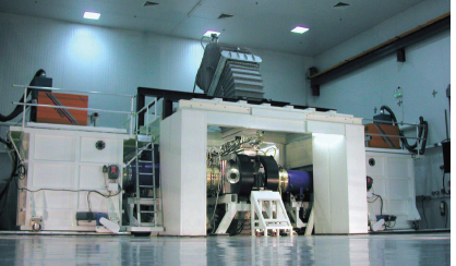
FIGURE 2.6 The 5 Hz, 700 J Electra laser at the Naval Research Laboratory. SOURCE: J.D. Sethian and S.P. Obenschain, “Krypton Fluoride Laser Driven Inertial Fusion Energy,” Presentation to the committee on January 29, 2011. See also J.D. Sethian et al., 2010, The science and technologies for fusion energy with lasers and direct drive targets, IEEE Transactions on Plasma Science 3: 690-703.
and supported with modeling at a scale to support KrF as a technical application approach for an IFE laser driver.
The KrF laser is suitable to illuminate direct-drive targets because of its UV wavelength. However, the projected 7 percent efficiency of the KrF laser requires a target gain of more than 140. For conventional direct-drive targets this would require a laser drive energy of 2.4 MJ. One strategy to decrease the drive energy is to use high-velocity direct drive.71 In this case, the required drive energy is calculated to be near 1 MJ. A second strategy, which would be more attractive if it is feasible, is to use relatively low driver energy to provide compression and to achieve ignition by applying a late but very high-peak-power shock ignition pulse (see Figure 2-2). Shock ignition, similar to fast ignition (see Figure 2-1), is attractive for laser-based inertial fusion energy because it may potentially decrease the driver energy by a factor of 5 from ~2 MJ (conventional direct drive) to approximately 0.4 MJ. However, it should be noted that neither fast ignition nor shock ignition has been explored
__________________________
71 S. Obenschain et al., 2006, Pathway to a lower cost high repetition rate ignition facility, Physics of Plasmas 13: 056320.
experimentally at the drive energies relevant for ignition. How driver size affects the capital cost of a plant and the cost of electricity is discussed in Chapter 3.
The homogeneous bandwidth of KrF is 3 THz; consequently, strongly time-randomized beams72 may be used to suppress laser-plasma instabilities. Theory predicts potential suppression of a particular instability when the laser coherence length becomes shorter than the relevant plasma scale length, which itself increases the thresholds: for example, for stimulated Brillouin scattering (SBS), the plasma velocity gradient, and for stimulated Raman scattering (SRS), the plasma density scale length.
The optical system of a KrF laser fusion amplifier focuses an incoherent KrF light source at the laser “front end” onto the target. This technique, called incoherent spatial imaging, allows a uniform intensity profile on the target, essential for acceleration with minimum growth of instabilities. Uniform irradiation has been demonstrated with KrF laser beams at NRL.73 Simulations of high-gain, direct-drive targets74 include the appropriate KrF spectrum of intensity fluctuations, modified to account for the typical number (approximately six) of overlapping beams at any point on the target surface.
The same optical design also allows dynamic focusing on a compressing target—or “zooming”—to improve efficiency by matching the focal spot to the shrinking pellet size during compression. This works by switching successively smaller incoherent source images into the front end of the laser. As the front end is imaged onto the target, the decrease in target size can be matched. Zooming has been demonstrated on the NRL Nike laser. It is calculated that approximately 1.5 times less laser energy is required to achieve fuel compression when zooming is employed.75
The KrF angular multiplexing geometry is well-suited for the generation of sub-nanosecond shock pulses, which can be done without any efficiency penalty, according to complete laser kinetic modeling.76 This works because the 0.2-ns shock spike extracts energy that has been stored in the KrF medium on the 1 ns timescale. Separate angular multiplex paths ensure that the full spike intensity is not experienced on any optical surface prior to synchronous arrival at the target, decreasing
__________________________
72 Intensity smoothing on a short timescale via the high frequency of fluctuations inherent in beams of high bandwidth.
73 J.D. Sethian and S.P. Obenschain, “Krypton Fluoride Laser Driven Inertial Fusion Energy,” Presentation to the committee on January 29, 2011.
74 A.J. Schmitt, 1984, Absolutely uniform illumination of laser fusion pellets, Applied Physics Letters 44: 399-401.
75 S.P. Obenschain and A.J. Schmitt, NRL, Presentations to the Target Physics Panel on September 20, 2011.
76 R.H. Lehmberg, J.L. Giuliani, and A.J. Schmitt, 2009, Pulse shaping and energy storage capabilities of angularly-multiplexed KrF laser fusion drivers, Journal of Applied Physics 106: 023103.
substantially the risk of optical damage. Because the 248 nm light is generated from the outset in the KrF medium, there is no need to frequency convert at the final optical stage via intensity-dependent nonlinear optical crystals that have limited dynamic range.
A beneficial feature for repetition rate operation of a gas medium in a KrF laser is that the waste heat is carried away by circulating the gas. Further, the gaseous laser medium is self-healing in the face of optical damage. The multiplexed beams propagate at approximately 100 times the diffraction limit and so are not significantly distorted by residual refractive index variations in the gas.
The wall-plug efficiency of a KrF laser is expected to exceed 7 percent, based on individual components that have been demonstrated at NRL. The separate demonstrations involve durable, solid-state pulsed power; guided electron-beam transmission through the foil support structure; and optical extraction. Although all components have not yet been demonstrated in a single device, these are separable efficiencies that multiply to generate the anticipated 7 percent efficiency. After nearly 10 years of development, KrF has delivered runs of 5 × 10⁴ pulses at 5 Hz (~3 h) and 1.5 ×10⁵ pulses at 2.5 Hz (~17 h) with 270 J/pulse.77
Scaling of KrF laser energy from its present 5 kJ to the 20 kJ module needed for a power plant has been the subject of detailed theoretical study78 Designs up to more than 50 kJ appear possible. In a 400 kJ facility, for example, 20 of the basic 20 kJ modules would be required. Continuous plant operation could be possible via the type of architecture proposed for the KrF FTF,79 in which spare modules can be switched into use by rotating the mirror a few degrees at the entry and exit of common beam transport ducts. The electron beams that drive the KrF gain medium can also be designed modularly for ease of substitution.
Scientific and Engineering Challenges and Future R&D Priorities for KrF Lasers for IFE Applications
The following are key KrF laser R&D priorities for the future, as described in presentations to the committee:
- Laser–plasma instabilities. This is discussed earlier in the chapter.
__________________________
77 J. Sethian and S. Obenschain, Naval Research Laboratory, “Krypton Fluoride Laser Driven Inertial Fusion,” Presentation to the committee on January 29, 2011.
78 R.H. Lehmberg, J.L. Giuliani, and A.J. Schmitt, 2009, Pulse shaping and energy storage capabilities of angularly-multiplexed KrF laser fusion drivers, Journal of Applied Physics 106: 023103, and references therein.
79 S.P. Obenschain, J.D. Sethian, and A.J. Schmitt, 2009, A laser based fusion test facility, Fusion Science and Technology 56: 594-603.
- The KrF laser lifetime, energy scale, pulse shaping, and optics. During the development of the Electra 5 Hz KrF laser at NRL, the solutions to integrated engineering challenges were demonstrated by system runs of greater than 105 pulses.80 Demonstrations still need to be extended to beyond 1.6 × 10⁸ pulses (one year at 5 Hz). The electron gun cathode is a critical element that has been demonstrated to greater than 5 × 10⁵ pulses (to date), and a prototypical solid-state, pulsed-power module has been tested to more than 107 pulses. The fatigue life of the foil barrier between the electron gun and the laser gas is theoretically sufficient for more than 108 pulses (at 370°C). Fatigue has not been a principal concern, but the foil life has been limited by reverse arcs that occur postpulse within the electron gun.81 Elimination of these arcs by tuning has extended the foil life to more than 105 pulses.82 Gas switches in the pulsed-power supply currently limit runs to 105 pulses, because they generate voltage spikes that cause that arcing. This problem is removed with solid-state pulsed power, which has already been demonstrated separately to more than 107 pulses, as noted above. The overall laser engineering challenge is to extend demonstrations from the greater than 105 level to the greater than 1-year level, and to understand the statistics of failure.
- The energy of a single module of the KrF laser. This is projected to scale to at least 16 kJ from existing systems.83 Higher module energy, up to 30 kJ, may be possible.84 In regard to the “front end” of the laser, where pulse shaping is done, NRL has identified85 a nonlinear optical process to transfer fiber laser waveforms (already well developed for the NIF laser system) to drive the KrF laser system. The bandwidth of the fiber laser system is 0.5 THz and the timing accuracy is 30 ps. It has been shown by detailed calculation that arbitrary shock ignition waveforms may be generated without an efficiency penalty in a KrF amplifier,86 although this has to be confirmed experimentally. Demonstration of “end-to-end” wall plug efficiency of 7 percent is an important development objective.
__________________________
80 J. Sethian and S. Obenschain, Naval Research Laboratory, “Krypton Fluoride Laser Driven Inertial Fusion,” Presentation to the committee on January 29, 2011.
81 Ibid.
82 Ibid.
83 Ibid.
84 R.H. Lehmberg, J.L. Giuliani, and A.J. Schmitt, 2009, Pulse shaping and energy storage capabilities of angularly-multiplexed KrF laser fusion drivers, Journal of Applied Physics 106: 023103, and references therein.
85 Ibid.
86 Ibid.
- The degradation of the laser windows by laser gas and the lifetime of the final optics are two challenges for the KrF driver optics. The first challenge deals with the slow degradation of the fused silica laser windows by the laser gas or, possibly, by moisture contamination within it. There are fallback approaches in which a fluorine-depleted gas layer is deployed next to the window or silica windows are changed to calcium fluoride. However, attention to gas purity and dryness may also solve the problem. The committee notes the commercial achievement of billion-pulse lifetimes in sealed KrF lasers for lithography. As for the second challenge, the final grazing-incidence metal mirror has not yet been fabricated or exposed to fusion neutrons. It will have to be composed of materials that are stable to moderate neutron flux. Designs have been developed that minimize its neutron exposure,87 and dielectric mirrors88 that are radiation-resistant have exhibited good optical damage resistance at 248 nm, even after irradiation. Further irradiation and damage testing is needed on optical elements that could serve as a plasma-facing final optic. Dielectric mirrors may qualify for this function. A magnetic field is probably required to divert fast ions before they can impact a final mirror, although X-ray energy bursts must also be withstood. Designs for magnetic field “intervention” have been proposed.89
Conclusion 2-5: The demonstration of a reactor-scale KrF module with a pulse count (before servicing) three orders of magnitude greater than presently achieved remains challenging. A key to achieving this goal would be integrating a solid state switching system into the Electra KrF laser at NRL.
Conclusion 2-6: If the KrF laser technical approach is selected for the roadmap development path, a very important element of the KrF laser inertial fusion energy research and development program would be the demonstration of a multi-kilojoule, 5-10 Hz, KrF laser module that meets all of the requirements for a Fusion Test Facility.
The timing for this step is discussed in Chapter 4.
A key R&D priority for the future is to conduct spherical direct-drive experiments using ganged 20 kJ KrF modules. The acceleration stability of 248-nm-irradiated
__________________________
87 L.L. Snead, K.J. Leonard, G.E. Jellison Jr., M. Sawan, and T. Lehecka, 2009, Irradiation effects on dielectric mirrors for fusion power reactor application, Fusion Science and Technology 56: 1069-1077.
88 Ibid.
89 J.D. Sethian, NRL, “The Science and Technologies for Fusion Energy with Lasers and Direct-Drive Targets,” Presentation to the committee on June 15, 2011; J.D. Sethian et al., 2010, The science and technologies for fusion energy with lasers and direct drive targets, IEEE Transactions on Plasma Science 38(4): 690-703.
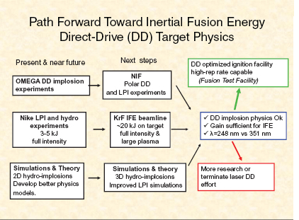
FIGURE 2.7 Diagrammatic laser IFE roadmap for direct-drive target physics research to prepare for an FTF. SOURCE: J.D. Sethian and S.P. Obenschain, NRL, “Krypton Fluoride Laser Driven Inertial Fusion Energy,” Presentation to the committee on January 29, 2011.
targets may be studied initially with 1-steradian segments of target and a single 20 kJ module as proposed below by the NRL (Figure 2.7), giving information at the precise intensity and scale lengths relevant to 240 kJ implosions. The effect of target design changes for different adiabats could then be understood in detail. With good results at this energy level, four or eight 20 kJ modules could be combined in order to refine the comparison of experiment to theory, particularly in regard to the shock ignition regime at 1016 W/cm2. Supporting the use of a relatively small number of beams is the Schmitt theorem on perfectly uniform illumination.90 With zooming, the Schmitt cosine-squared intensity profile can be adjusted to the decreasing pellet size during compression, maintaining uniformity.
__________________________
90 A.J. Schmitt, 1984, Absolutely uniform illumination of laser fusion pellets, Applied Physics Letters 44: 399-401.
Path Forward for KrF Laser-Based IFE
Figure 2-7 outlines a path forward for exploration of laser direct-drive target physics involving both solid-state and KrF laser drivers. The plan for KrF laser drivers that immediately follows it is based on the NRL submission to the committee, with the exception, as noted, of ganged 20 kJ modules for exploration closer to reactor scale.
Near-Term R&D Objectives (≤5 Years)
Subscale components would be as follows:
• Convert Electra repetitive KrF facility to solid-state pulsed power (path known).
• Develop front-end discharge amplifier (design available) and build pulseshaper.
• Design and test components for prototype 20 kJ module, initially at 0.01 Hz.
• Refine target design and physics.
• Complete efforts on other IFE technologies begun in the HAPL program:
—Chamber physics (engineered walls, magnetic intervention);
—Chamber technology (blanket, neutronics);
—Materials (experimental and theoretical);
—Final optics (grazing incidence metallic mirrors, dielectrics);
—Target fabrication (shells, layering); and
—Target injection and tracking.
The cost guidance for this Phase I (estimate provided by NRL) was as follows. For the KrF target physics and laser development alone, approximately $25 million per year would be required over 3-4 years. A program that included development of essential auxiliary technologies (target fabrication, fusion materials, and system studies to provide guidance) would cost about two to three times that amount. As a point of comparison, the HAPL program peaked at $25 million per year in 2006.
Medium-Term (5-15 Years)
Phase II would consist of a full-size KrF laser beam line (20 kJ at 5 Hz) along with other inertial fusion energy components. As shown in Figure 2.7, the following steps assume testing of polar direct drive on the NIF:
- Build and test 20 kJ, 5 Hz beam line.
- Engage targets injected into test chamber with beam line.
- Develop all critical inertial fusion energy technologies (e.g. low-cost targets, full-size final optics) for the Fusion Test Facility.
- Develop high confidence in pellet designs and physics (using NIF and KrF beam line).
The cost guidance for this Phase II (provided by NRL) estimates that $50 million per year over 5 years would enable development of a full-scale KrF beam line for the FTF and demonstration of highly reliable operation. The overall Phase II program would require about $150 million to $200 million per year to develop all the required technologies for the FTF and to design it. Additional ganged 20 kJ modules for higher energy target experiments will cost between $10 million and $20 million each, over and above the NRL estimated Phase II cost.
Long-Term R&D Objectives (>15 Years)
The FTF with a 500 kJ KrF laser that will do the following:
- Show that IFE components routinely perform with precision and durability.
- Optimize target performance.
- Develop, test, and qualify fusion materials and components.
- Demonstrate reliable operation with nominal 250 MW fusion power.
- Attract significant participation by private industry.
- Provide the technical and cost basis for full-scale power plants.
It is too early to develop reliable cost estimates for the Phase III work of building and operating the FTF. Use of a KrF driver is predicted to reduce the driver energy requirements substantially, with a beneficial impact on the cost.
Heavy-Ion Accelerators
Background and Status
The U.S. Department of Energy supported the development of heavy-ion accelerators for fusion power production until 2003, and it funded several conceptual power plant designs for both accelerator and laser drivers. The most recent conceptual design for a heavy-ion power plant91 used an induction linear accelerator (linac), ballistic neutralized focusing, a thick liquid-protected wall, and an
__________________________
91 S.S. Yu, W.R. Meier, R.P. Abbott, et al., 2003, An updated point design for heavy ion fusion, Fusion Science and Technology 44: 266-273.
indirectly driven target. This design utilized singly charged bismuth ion beams at ≤4 GeV, an accelerating gradient ≤1.5 MV/m, and a linac length exceeding 3 km. The total beam energy was 7 MJ with target gain of 60. The linac was based on standard components: warm-bore, superconducting quadrupole magnets, thyratron pulsers, and then available ferromagnetic materials for the induction cores.
The most recent two-dimensional simulations of indirectly driven targets, carried out by LLNL, showed better performance than the target used for the conceptual power plant design. Specifically, the simulations indicated that it would be possible to achieve gains on the order of 90 to 130 at beam energies from 1.8 to 3.3 MJ, respectively.92 The two-dimensional codes used were the same as those used for laser drivers, but the X-rays were produced when the ion beams hit material inside the hohlraum rather than the hohlraum walls, as with laser beams. NIF tests should lead to a better understanding of the performance of such indirect targets.93
There are multiple accelerator options for heavy-ion fusion (HIF). The two most promising options are induction accelerators and radio-frequency (RF) accelerators. There has not been sufficient funding to develop both options in the United States. For more than two decades, there has been an informal understanding that Europe and Japan would pursue the RF option while the United States would pursue the induction option. The largest foreign programs are based on existing or planned multipurpose RF accelerators using storage rings. Since these accelerators are multipurpose machines, they are not ideally matched to some of the requirements of IFE. Nevertheless, the largest of the new machines, the Terawatt Accelerator (TWAC) at the Institute for Theoretical and Experimental Physics in Moscow and FAIR at GSI in Darmstadt, will be much more able to create high temperatures and high pressures (pressure predicted to be in the 1-100 Mbar regime) than existing U.S. induction accelerators.94 TWAC is currently under construction, and ground has just been broken for FAIR.
In addition to the foreign programs, the privately funded Fusion Power Corporation in the United States has been exploring the possibility of using radio-frequency technology without storage rings to power multiple reaction chambers.95
Beneficial Features of Heavy-Ion Fusion
Heavy-ion drivers have a number of beneficial characteristics:
__________________________
92 D. Callahan-Miller and M. Tabak, 2000, Progress in target physics and design for heavy ion fusion, Physics of Plasmas 7: 2083-2091.
93 J.D. Lindl, P. Amendt, R.L. Berger, et al., 2004, The physics basis for ignition using indirect-drive targets on the National Ignition Facility, Physics of Plasmas 11: 339-491.
94 B. Sharkov, FAIR, “Heavy Ion Inertial Fuse Ion Energy—Activities in Europe and in Russia,” Presentation to the committee on October 31, 2011.
95 C. Helsley, Fusion Power Corporation, Presentation to the committee on February 22, 2012.
- High-energy particle accelerators of megajoule-scale beam energy have separately exhibited efficiencies, pulse rates, average power levels, and durability required for IFE.
- The relatively high efficiency permits the use of indirect drive, and liquid walls can be used because the high-energy beams can penetrate through high vapor pressure caused by the hot liquid.
- Heavy ions deposit their energy within the case volume. The cases protect the fuel capsules as they move toward the center of a hot reaction chamber.
Recent Successes
In recent years, the program has been undertaken by a Virtual National Laboratory consisting of LBNL, LLNL, and the Princeton Plasma Physics Laboratory (PPPL), with additional work at the University of Maryland.
- The Single Beam Transport Experiment demonstrated that space-charge-dominated beams could be transported without emittance growth, as required for heavy-ion fusion. Emittance growth degrades the ability to focus the beam. If emittance growth were excessive, heavy ion fusion would not be feasible.
- Multiple-beam experiments addressed acceleration, current amplification, longitudinal confinement, and multibeam transport. The high-current experiment studied driverlike beam transport. The three-dimensional particle simulations using WARP code modeled secondary electrons successfully.
- Beam transport with driver-scale line-charge density and without emittance growth was demonstrated.
- Beams were compressed from 500 ns to a few nanoseconds in the neutralized drift compression experiment-1 (NDCX-I).
- Beams were focused to millimeter spot size using innovative plasma sources.
- An end-to-end numerical simulation capability was developed.
Scientific and Engineering Challenges and Future R&D Priorities for Heavy-Ion Accelerators for IFE Applications
As is the case for nearly all credible fusion options, the projected cost of electricity in earlier studies96 was higher than the cost for many existing power options
__________________________
96 S.S. Yu, W.R. Meier, R.P. Abbott, et al., 2003, An updated point design for heavy ion fusion, Fusion Science and Technology 44: 266-273; DOE, 1992, OSIRIS and SOMBRERO Inertial Fusion Power Plant Designs, Final Report, DOE/ER/54100; DOE, 1992, Inertial Fusion Energy Reactor Design Studies, PROMETHEUS-L and PROMETHIUS-H, Final Report, DOE/ER/54101. More recent design studies that have been reviewed as rigorously as those cited here do not exist in this case.
such those based on fossil fuels or fission. However, the projected cost of electricity was usually lower with heavy-ion fusion than with the laser option, partly because of the comparatively high efficiency of heavy-ion drivers (calculated to be 25 to 40 percent).97 It should be noted that large accelerators often exceed the repetition rate required for IFE. For example, the Spallation Neutron Source operates at 60 Hz, and intershot switching might allow operation with multiple chambers. Nevertheless, cost reduction remains an important challenge. The cost of the accelerator decreases with decreasing target energy and more relaxed requirements on beam quality and alignment tolerances. For this reason, a cost reduction program should include improved target designs. There has been significant progress in this area.98 Also, prior to its termination in 2003, the HIF program had initiated a multipronged program to reduce the cost of accelerators. This program included development of the following:
- Inexpensive, compact, long-life ion sources.
- Compact, quadrupole magnet arrays amenable to robotic assembly or other mass production techniques. Some cold-bore quadrupole designs used a cooled liner, similar to Large Hadron Collider technology.99 This technology was expected to lead to smaller, less expensive accelerators than the warm-bore option.
- High-gradient insulators cast from glassy ceramics or fabricated from other materials. The object was to reduce manufacturing costs and increase the acceleration gradient to reduce the length and cost of the accelerator.
- Advanced solid-state pulsers using technology similar to that proposed for KrF lasers and pulsed-power fusion.
- Better ferromagnetic materials. This effort involved working with vendors to reduce the cost of newly developed, low-loss materials and interlaminar insulation techniques.
Although the cost reduction program and other parts of the program aimed at fusion energy were discontinued in 2003, accelerator development was fortunately able to continue at a modest budget level in support of high-energy-density physics research. Most recently, Recovery Act funds have allowed the construction of the NDCX-II accelerator. Because NDCX-II incorporates some features of a power plant driver, albeit at small scale, it provides a very good test bed for the validation
__________________________
97 See the DOE reports listed in the preceding reference.
98 D. Callahan-Miller and M. Tabak, 2000, Progress in target physics and design for heavy ion fusion, Physics of Plasmas 7: 2083-2091.
99 O. Groebner, The LHC vacuum system, Proceedings of the 1997 Particle Accelerator Conference, IEEE Catalog Number 97CH36167, p. 3542.
of theory and simulation. While NDCX-II is not the ideal first step if IFE rather than high-energy-density physics research is the primary goal, it will help to resolve some of the critical issues needed to determine heavy-ion fusion’s feasibility.
Two important requirements for IFE are high repetition rates and driver durability. In regard to these requirements, existing large accelerators often meet or exceed fusion requirements.100 For example, the average beam power in large storage rings can readily exceed 1 TW.101 Specific challenges include the following:
- Demonstrating the projected HIF accelerator efficiency of 25 to 40 percent. Note that existing accelerators have a maximum efficiency of 12 percent, but studies in Europe, India, and the United States (of radio-frequency accelerators) suggest that between 37 and 45 percent is possible.102
- Narrowing the uncertainty in the attainable accelerating electric field gradient.
- Developing long-life ion sources and the other reliable and durable accelerator technologies noted above. These developments are needed to provide reliable data on efficiency and cost, and for defining the acceptable level of trips and the necessary redundancy to accommodate them. Optimizing plasma source development technology for intense ion-beam pulse compression and focusing.
- Raising the beam energy from ~1 J to ~100 kJ per beam. The voltage must be increased from 10 MeV to a few GeV, and the beam current must be increased from amperes to ~kiloamperes per beam.
__________________________
100 See J. Jowett, 2011, “Heavy Ions in 2011 and Beyond, Chamonix,” 2011 LHC Performance Workshop, January 2-28, available at http://indico.cern.ch/conferenceOtherViews.py?view=standard&confId=103957; R.S. Moore, “Review of Recent Tevatron Operations,” Proceedings of the Particle Accelerator Conference 2007, available at http://accelconf.web.cern.ch/AccelConf/p07/PAPERS/TUOCKI01.PDF; L. Rivkin, (LPAP) “PSI Sets World Record with 1.4 MW Proton Beam,” available at http://actu.epfl.ch/news/psi-sets-world-record-with-14-mw-proton-beam/; M. Seidel, S. Adam, A. Adelmann, et al., 2010, “Production of a 1.3 MW Proton Beam at PSI,” Proceedings of IPAC’10 p.1309-1313, available at http://accelconf.web.cern.ch/accelconf/IPAC10/papers/tuyra03.pdf; T. Hardek, M. Crofford, Y. Kang, S-W Lee, et al., “Status of the Oak Ridge Spallation Neutron Source (SNS) RF Systems,” available at http://accelconf.web.cern.ch/AccelConf/PAC2011/papers/thoas3.pdf; K. Takayama and R.J. Briggs (eds.), 2011, “Induction Accelerators,” Particle Acceleration 7 and Detection, DOI 10.1007/978-3-642-13917-8_2, Springer-Verlag, available at http://www.springer.com/physics/particle+and+nuclear+physics/book/978-3-642-13916-1.
101 S. Myers, “Four Decades of Colliders (from the ISR to LEP to the LHC),” Proceedings of IPAC’10, Kyoto, Japan, available at http://accelconf.web.cern.ch/AccelConf/IPAC10/papers/thppmh03.pdf.
102 S.S. Kappoor, 2002, Accelerator-driven sub-critical reactor system (ADS) for nuclear energy generation, Indian Academy of Sciences 59: 941; and B. Aune et al., 2001, “SC Proton Linac for the CONCERT Multi-Users Facility,” Particle Accelerator Conference, 2001.
- Refining the designs of the final optics and focusing system for reactor-level beams.
- Developing and testing targets that have lower input energy requirements.
- Demonstrating technologies needed to produce repetitively cycled liquid walls.
The committee notes as follows:
- While the base case considered for HIF uses an induction linac, indirect drive, and thick liquid walls, other options are possible, such as polar direct drive, shock ignition, and thin liquid or solid walls. Polar direct drive is an option that is currently being studied for both lasers and ion beams. If direct drive is successful, it is expected to have lower energy requirements and higher gain than indirect drive. Moreover, polar illumination with heavy-ion beams is compatible with the thick liquid wall chambers. These chambers minimize material damage problems.
- The final optics in HIF can be shielded from the neutrons, and neutronics calculations indicate lifetimes ≥100 years.103 However, if the option of neutralized ballistic transport with in-vessel plasma sources were to be used, additional analysis would be required in regard to the plasma sources.
- Fast ignition and other target options, such as the X-target,104 are being studied.105 As a matter of historical interest, the first target considered for HIF was based on fast ignition.106
Path Forward for Heavy-Ion Accelerator-Based IFE
The plan for HIF IFE that follows is based on information provided to the committee by LBNL.
Near Term (≤5 Years)
- Continue the program in high-energy-density physics on the NDCX-II facility.
__________________________
103 J.F. Latkowski and W.R. Meier, 2003, Shielding of the final focusing system in the robust point design, Fusion Science and Technology 44: 300.
104 See Figure 2-6 in the Target Physics Panel report for an image of the x-target.
105 G. Logan, LBNL, “Heavy Ion Fusion,” Presentation to the committee on January 29, 2011, and personal communication with D. Lang, NRC, in June 2011.
106 A.W. Maschke, 1975, Relativistic ions for fusion applications, Proceedings of the 1975 Particle Accelerator Conference, Washington, D.C., IEEE Transactions on Nuclear Science NS-22 (3): 1825.
- Show agreement with benchmark simulations and end-to-end simulation in NDCX-II.
- Continue the collaboration with foreign heavy ion accelerator programs.
Conclusion 2-7: Demonstrating that the Neutralized Drift Compression Experiment-II (NDCX-II) meets its energy, current, pulse length, and spot-size objectives will be of great technical importance, both for heavy-ion inertial fusion energy applications and for high-energy-density physics.
It is important to recognize that the high-energy-density physics program, including NDCX-II, is, by itself, not a fusion energy program. Indeed, a number of program elements needed for an IFE program would have to be added:
- Restart the High-Current Experiment (HCX) (see Figure 2.8) accelerator to complete driver-scale beam-transport experiments that were dropped when the HIF program was terminated in 2003. These would include emittance evolution, electron clearing, and dynamic vacuum control in quadrupoles at 5 Hz. The HCX was designed to be close to driver scale in important parameters such as beam size, charge density, and pulse length. Furthermore, the lattice technology closely approximates fusion driver technology. Funding required107 is ~$1.5 million for the first year and up to $8 million in subsequent years, which includes some of the enabling technology.108
- Restart the enabling technology development, including magnet arrays, pulsers, and the other technologies listed earlier in this section. This will provide the information needed to address issues of efficiency, cost, maintenance, and reliability. In particular, the projected efficiency of 25 to 40 percent and gradients >1.5 MV/m require experimental validation.
Conclusion 2-8: Restarting the High-Current Experiment to undertake driver-scale beam transport experiments and restarting the enabling technology programs are crucial to reestablishing a heavy-ion fusion program.
- Carry out scaled liquid-chamber experiments. HIF and the pulsed-power approaches to fusion appear to be the most likely driver technologies to allow the use of thick liquid walls.
__________________________
107 As estimated by G. Logan in a presentation to the committee in January 2011.
108 According to G. Logan (ibid.), this is an absolute minimum budget to restart the HIF program. A higher level of funding would be required to move the program expeditiously if a vigorous inertial fusion energy program is supported.
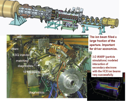
FIGURE 2.8 The HCX apparatus. SOURCE: G. Logan, LBNL, “Heavy Ion Fusion,” Presentation to the committee on January 29, 2011.
- Expand the target design effort, and as NIF data come in, continually determine the implications for HIF target modeling.
Conclusion 2-9: Although no serious beam-target interaction issues have been found, the work in this area is dated. Beam parameters, particularly for some targets, have evolved into regions where the previous work may no longer be valid.
- Refine final optics design using neutronics codes; include sufficient bends to reduce the neutron flux at the end of the accelerator to a hands-on level. Assess the need for radiation-resistant plasma sources.
- Do a power plant study of the reference ≥3 MJ target approach for a liquid-wall chamber.
Medium Term (5-15 Years)
Conclusion 2-10: A very important element of the heavy ion inertial fusion energy research and development program will be the demonstration of a ≥10 kJ scale target physics facility, supporting target fabrication and injection R&D for burst-mode experiments at ~5 Hz.
This intermediate research experiment (see Chapter 4) has been proposed because, unlike the other IFE approaches, HIF has no target test bed. It is therefore critical for such an HIF facility to be able to test targets and operate in an environment as relevant to IFE as possible.
The timing for this step is discussed in Chapter 4 and Appendix J.
- Continue technology development and cost reduction with vendors for the long term.
Long Term (>15 Years)
- Construct a 2-3 MJ HIF ignition test facility, first for single-shot tests, then for burst mode, using an accelerator designed for high repetition rate. If successful, add nuclear systems to upgrade to 150 MW average-fusion-power level heavy-ion Fusion Test Facility/DEMO (HIFTF).
The programs described above are illustrated in Figure 2.9.
Observations
HIF benefits greatly from the large NNSA target physics program. The design codes are suitable for the simulation of heavy-ion targets and the target fabrication techniques are similar. Moreover, for indirect drive, the physics of the fuel capsule itself is largely independent of the source of the X-rays used to drive the fuel capsule as long as the X-rays have the correct spectrum (approximately thermal), time dependence, and symmetry.
One of the goals of the NIF is to establish the feasibility of indirectly driven targets for all drivers.109 Although NIF can provide significant confidence in indirect drive for any driver, each driver must ultimately demonstrate that it can deliver the appropriate hohlraum conditions needed to drive the capsule.
__________________________
109 J.D. Lindl, P. Amendt, R.L. Berger, et al., 2004, The physics basis for ignition using indirect-drive targets on the National Ignition Facility, Physics of Plasmas 11: 339-491.
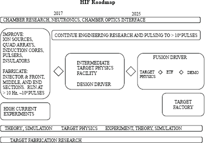
FIGURE 2.9 Illustrative HIF roadmap, based on the program described in the text.
Theory and existing experimental data suggest that well focused heavy-ion beams can produce the required hohlraum environment,110 but there is currently no heavy-ion accelerator that can test the theory at the beam intensities needed for fusion. The final validation of the theory will require the construction of new facilities as shown in the roadmap above.
The heavy-ion accelerator development path differs from the development path for solid-state lasers. Much of the technology for large, solid-state lasers has been developed by the NNSA ICF program for Stockpile Stewardship. In contrast, much of the needed accelerator technology has been developed for nuclear and particle physics and, in the case of induction accelerators, for radiography and other
__________________________
110 See A.W. Maschke, 1975, Relativistic ions for fusion applications, Proceedings of the 1975 Particle Accelerator Conference, Washington, D.C., IEEE Transactions on Nuclear Science NS-22 (3): 1825; D. Eardley et al., 1983, Heavy-ion fusion, JASON Report JSR-82-302, The MITRE Corporation, McLean, Virginia; H.H. Heckman, H.R. Bowman, Y.J. Jarant, J.O. Rasmussen, A.I. Warwick, and Z.Z. Xu, 1987, Range energy relations for Au ions, E/A ≤ 150 MeV, Physical Review A 36: 3654; D.W. Hewett, W.L. Kruer, and R.O. Bangerter, 1991, Corona plasma instabilities in heavy-ion fusion targets, Nuclear Fusion 31(3): 431 and references therein.
applications requiring high-current electron beams. There is an existing industrial base, but the technology must be adapted to the unique requirements of IFE.
Since accelerators are expected to be efficient and reliable and to have high pulse repetition rates, it seems possible to skip one step in the accelerator development path relative to solid-state lasers. Specifically, after building a number of smaller lasers, the laser program in the United States built two tens-of-kilojoules, single-shot laser facilities: Nova and OMEGA. The intermediate target physics facility mentioned above is of similar scale, but it is repetitively pulsed. These laser facilities were followed by the NIF. Since the NIF does not have the characteristics needed for power production, at least one additional step is required. The heavy-ion plan outlined above skips the NIF step. The proposed HIF Ignition Test Facility will initially be built without all the power supplies needed for high-repetition-rate operation. At this point, it will be used to refine and validate those aspects of target physics that have not yet been tested at full scale. The committee emphasizes again that much of the target physics, target fabrication technology, and needed diagnostics will already have been developed at the NIF and elsewhere. The final step in accelerator development program is to add the power supplies needed for high-repetition-rate operation.
Pulsed Power
Background and Status
Pulsed-power-driven IFE would utilize ≥50 MA of current from a pulsed-power accelerator to generate sufficiently high magnetic field pressures to compress and heat magnetized, preionized fusion fuel contained in a cylindrical target to ignition conditions. The pulsed-power approach has relatively low-cost and high-efficiency driver technology that appears to be scalable in a straightforward way to the peak power and total energy presently estimated to be needed for IFE. Furthermore, a high-repetition-rate technology development program is already in progress because of synergistic NNSA programs and potential commercial applications other than energy use for this technology.111
The primary conceptual approach to achieving pulsed-power IFE, Magnetized Liner Inertial Fusion (MagLIF), is a direct-drive approach—that is, fuel compression and heating are driven directly by magnetic pressure (see Figure 2.3). This approach offers the potential benefits of a relatively simple cylindrical target geometry and highly efficient delivery of driver energy to fuel implosion and heating. However, there is considerable uncertainty (i.e., technical risk) surrounding
__________________________
111 Note, however, that these commercial applications involve storing energy at much lower levels than those necessary for IFE.
all aspects of this approach owing to a paucity of relevant experimental data on target physics and ignition and a lack of indepth design studies on inertial fusion reactors at the proposed multi-GJ yield and ~0.1 Hz repetition rate called for by the advocates. In addition to MagLIF, there other promising approaches to pulsed-power fusion energy, including one called magnetized target fusion (MTF). While MagLIF operates on the 100-ns timescale, is ~1 cm in size, and involves open magnetic field lines, MTF operates on a ~1 μs timescale, is tens of centimeters in size, and involves closed (field-reversed) magnetic field lines.
A pulsed-power fusion reactor system would be very different from both laser-and heavy-ion fusion systems. As such, the technological or economic failure modes are likely to be very different.
Historical Background
The use of <100-ns-pulse-duration, intense electron beams driven by pulsed-power generators for ICF was first discussed in the mid-1960s at Physics International Company as pulsed-power generators capable of hundreds of kiloamperes and ~10 MeV were being developed there and elsewhere.112 F. Winterberg appears to have the earliest full publications on the subject.113 Sandia National Laboratories (SNL) initiated a research program on pulsed-power-driven IFE with intense electron beams in the early 1970s.114 This became the light-ion fusion program in 1979, when the advantages of intense light-ion beams relative to electrons were recognized and it became possible to produce intense light-ion beams efficiently.115 Some progress on the generation of adequately intense light-ion beams using pulsed-power generators was made by the middle 1990s.116 However, the demonstration of efficient coupling of electrical energy into magnetic energy and then to soft X-rays (through the intermediary of imploding cylindrical wire-array Z-pinches with hundreds of fine tungsten wires)117 deflected the pulsed-power-driven inertial fusion community in the direction of radiation-driven (indirect-drive) fuel-capsule
__________________________
112 F.C. Ford, D. Martin, D. Sloan, and W. Link, 1967, Bulletin of the American Physical Society 12: 961.
113 F. Winterberg, 1968, The possibility of producing dense thermonuclear plasma by an intense field emission discharge, Physical Review 174: 212-220.
114 G. Yonas, J.W. Poukey, and K.R. Prestwich, 1974, Electron beam focusing and application to pulsed fusion, Nuclear Fusion 14: 731-740.
115 See, for example, J.P. VanDevender, 1986, Inertial confinement fusion with light ion beams, Plasma Physics and Controlled Fusion 28: 841-855.
116 J.P. Quintenz, T.A. Mehlhorn, R.G. Adams, G.O. Allshouse, et al., 1994, Progress in the light ion driven inertial confinement fusion program, Proceedings of 15th International Conference on Plasma Physics and Controlled Nuclear Fusion Research 3: 39-44.
117 T.W.L. Sanford, G.O. Allshouse, B.M Marder, et al., 1996, Improved symmetry greatly increases X-ray power from wire-array Z-pinches,” Physical Review Letters 77: 5063-5066.
implosions. The even higher potential efficiency of magnetically driven (direct-drive) ignition of magnetized fusion fuel—MagLIF—and recent favorable computer simulation results for this concept have caused MagLIF to become a leading candidate for pulsed-power fusion energy.118
Imploding a magnetized, field-reversed target plasma in a solid or liquid liner by a pulsed external magnetic field is a 1970s (or earlier) idea that has been pushed from the millisecond to the microsecond timescale in the present embodiment, MTF.119 This approach is very properly described as a hybrid of magnetic and inertial confinement fusion, since the magnetic field configuration is a closed-confinement geometry. However, the duration of confinement—should fusion reactions be ignited—is determined by the inertia of the imploding liner.
Status
The necessary high-efficiency, 0.1-1 pulse-per-second pulsed-power technology is close to being in hand, and the cost per joule of energy delivered to the fusion target load is projected to be substantially lower than for all other drivers. Proof of principle that the necessary driver for a fusion reactor can be built for an acceptable price is possible within 6 years, according to the advocates.120
Thus far, target physics for MagLIF has been addressed only through computer simulations.121 However, current research program plans at SNL include addressing many target physics issues using existing facilities as part of the NNSA-sponsored (single-pulse) ICF program.122
On the reactor side, the present MagLIF approach as proposed by SNL involves extremely high-yield pulses (~10 GJ) at a repetition rate on the order of 1 per 10 s (~0.1 Hz). This makes some of the proposed reactor challenges unique, such as the requirement for power delivery to the fusion fuel by a recyclable transmission
__________________________
118 M. Cuneo et al., SNL, “Pulsed Power IFE: Background, Phased R&D, and Roadmap,” Presentation to the committee on April 1, 2011; M.E. Cuneo et al., SNL, Response to the committee, submitted in March 2011; S.A. Slutz, M.C. Herrmann, R.A. Vesey, et al., 2010, Pulsed-power-driven cylindrical implosions of laser pre-heated fuel magnetized with an axial magnetic field, Physics of Plasmas 17: 056303.
119 G. Wurden and I. Lindemuth, LANL, “Magnetio-Inertial Fusion (Magnetized Target Fusion),” Presentation to the committee on March 31, 2011.
120 M. Cuneo, et al., SNL, “Pulsed Power IFE: Background, Phased R&D, and Roadmap,” Presentation to the committee on April 1, 2011; M.E. Cuneo et al., SNL, Response to the committee, submitted in March 2011.
121 S.A. Slutz, M.C. Herrmann, R.A. Vesey, et al., 2010, Pulsed-power-driven cylindrical implosions of laser pre-heated fuel magnetized with an axial magnetic field, Physics of Plasmas 17: 056303.
122 M. Cuneo et al., SNL, “Pulsed Power IFE: Background, Phased R&D, and Roadmap,” Presentation to the committee on April 1, 2011; M.E. Cuneo et al., SNL, Response to the committee, submitted in March 2011.
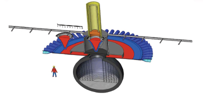
FIGURE 2.10 Recyclable transmission line concept with liquid wall chamber. SOURCE: M. Cuneo, SNL, Presentation to the committee on April 1, 2011.
line (RTL) (see Figure 2.10).123,124 There has been some analysis, and some small-scale experiments have been carried out that address how such high yields might be sustained repetitively in a reactor chamber.125
Single-pulse tests of MTF are being done now with the Shiva Star facility at the Air Force Research Laboratory at 6 MA. Next-generation tests are proposed that would use explosively driven, high-magnetic-field generation to drive the implosion, but IFE would require a high-repetition-rate pulsed-power driver. Reactor considerations for this concept have not been developed in detail to the committee’s knowledge.
__________________________
123 The recyclable transmission line is destroyed during each shot. Because it contains a considerable mass of material, economical operation dictates that this material be recycled.
124 See M. Cuneo et al., SNL, “Pulsed Power IFE: Background, Phased R&D, and Roadmap,” Presentation to the committee on April 1, 2011; M.E. Cuneo et al., SNL, Response to the committee, submitted in March 2011; and J.T. Cook, G.E. Rochau, B.B. Cipiti, et al., Z-inertial fusion energy: Power plant final report FY06, Sandia National Laboratories report SAND2006-7148.
125 See J.T. Cook, G.E. Rochau, B.B. Cipiti, C.W. Morrow, S.B. Rodriguez, C.O. Farnum, et al., 2006, Z-inertial fusion energy: Power plant, SAND2006-7148, Sandia; M. Sawan, L. El-Guebaly, and P. Wilson, 2007, Three dimensional nuclear assessment for the chamber of Z-pinch power plant, Fusion Science and Technology 52: 753; S.B. Rodríguez, V.J. Dandini, V.L. Vigíl, and M. Turgeon, 2005, Z-pinch power plant shock mitigation experiments, modeling and code assessment, Fusion Science and Technology 47: 656; S.I. Abdel-Khalik and M. Yoda, 2005, An overview of Georgia Tech studies on the fluid dynamics aspects of liquid protection schemes for fusion reactors, Fusion Science and Technology 47: 601; S.G. Durbin, M. Yoda, and S.I. Abdel-Khalik, 2005, Flow conditioning design in thick liquid protection, Fusion Science and Technology 47: 724.
Scientific and Engineering Challenges and Future R&D Priorities for Pulsed-Power IFE Applications
Implosion of magnetized plasma inside a conducting cylinder on open field lines to achieve fusion ignition depends on magnetic inhibition of radial energy transport and effective fusion burn before the hot plasma can run out the ends. MagLIF would achieve this with a ~100 ns implosion time and a few centimeters of high-density plasma confined by open magnetic field lines. Thus, the major target physics challenges that are to be addressed in the near term on Z are the following:
- Demonstrating that the predicted high-efficiency energy transfer from electrical energy to hot magnetized fusion fuel plasma compressed by magnetic-field-driven implosion of a cylindrical conducting liner occurs in experiments. Determining plasma conditions inside the imploding liner is a major part of this challenge.
- Demonstrating that the energy-loss rate of the compressed plasma is much less than that of an unmagnetized plasma. Understanding how the magnetic field affects the transport coefficients is a necessary part of this research to allow validating the design codes.
The MTF version of the two items is to demonstrate at 6 MA that a sufficiently well-confined plasma can be produced to warrant explosively driven experiments that have a much higher cost than the pulsed-power experiments. As in MagLIF, diagnostic access to the plasma if it is not generating the predicted number of neutrons is very limited, again making determination of the plasma condition inside the liner a part of this challenge.
The biggest early technology challenge for pulsed-power IFE is establishing the technical credibility of the proposed low-repetition-rate (~0.1 Hz), ~10 GJ yield-per-pulse reactor concept. The recyclable transmission line approach for delivering the current from the pulsed-power system to the fusion-fuel-containing target must be demonstrated to be technically feasible. Technical issues that must be addressed for the transmission line include these: what material to use, how thick it must be, and how to recycle it economically; how best to load the assembly in the reactor chamber (bearing in mind that the fusion-fuel-containing load—possibly requiring cryogenics—must be attached to it); and how to assure that the assembly makes a good electrical connection to the pulsed-power system.
Demonstrating the engineering feasibility of a thick-liquid-wall reactor chamber is a challenge that pulsed-power shares with other possible approaches, particularly heavy-ion fusion. However, pulsed-power fusion, as most recently proposed, is alone in requiring compatibility of the reactor chamber with recyclable transmission lines and with ~10 GJ yield per pulse (the equivalent of 2.5 tons of high
explosive). Some analyses of fatigue and nucleonics limits of possible chamber materials and some experimental studies relevant to thick liquid wall reactor chambers have been carried out,126 but much work is yet to be done here. Design and execution of a hydrodynamically equivalent experiment that could be conducted in a smaller “scaled” chamber at a much-reduced energy level should be part of the Phase 1 research program (see Table 2-3). This research would benefit heavy-ion fusion as well. If there is no technically viable solution to the reactor chamber problem at 10 GJ that is also economically viable, then pulsed-power fusion researchers will have to reoptimize their system design at a lower energy per pulse and a higher repetition rate than 0.1 Hz. Thus, the technical and economic feasibility of the 10 GJ yield system should be evaluated as early in Phase 1 as possible.
Given the state of development of linear transformer drivers (LTDs) (see Figures 2.11 and 2.12),127 the technology challenges associated with the pulsed-power system appear to be much less daunting than those discussed above. Nevertheless, the technology must still be demonstrated to be extremely reliable, as there would be hundreds of thousands of switches and a million capacitors in a pulsed-power reactor driver.128 Furthermore, the driver must be demonstrated to be compatible with using recyclable transmission lines, including their potential failure modes (e.g., sparking due to poor connections).
Many of the scientific issues having to do with MagLIF target physics can be addressed using existing facilities in the next 5 years, and many will be investigated as part of the NNSA-sponsored (single-pulse) ICF program at SNL. It is anticipated that this program will be funded at an estimated level of $6.8 million to $8.5 million per year through 2017.129 All pulsed-power approaches call for recyclable transmission lines and extremely high-yield pulses at a repetition rate of ~0.1 Hz, and these requirements make some of the necessary research and development for pulsed-power IFE unique. The high repetition rate driver technology needed for fusion via pulsed power is currently receiving development funding at the rate of $1.5 million to $3.3 million per year,130 and steady progress is being made.
The engineering feasibility challenges of MagLIF should be addressed early in the program, along with the target physics, to assess the viability of pulsed-power fusion. To do this, new funding would be required starting in 2013 at the level
__________________________
126 Ibid.
127 W. Stygar, SNL, “Conceptual Design of Pulsed Power Accelerators for Inertial Fusion Energy,” Presentation to the committee on April 1, 2011.
128 J.T. Cook, G.E. Rochau, B.B. Cipiti, C.W. Morrow, S.B. Rodriguez, C.O. Farnum, et al., 2006, Z-inertial fusion energy: Power plant, SAND2006-7148.
129 M. Cuneo, personal communication to committee member D. Hammer on November 2, 2011.
130 Ibid.
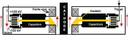
FIGURE 2-11 Pictorial representation of a side section of an annular LTD cavity where the load now is the coaxial line formed by the inner cylindrical surface of the cavity and the central (cathode) cylindrical electrode. The red arrows show the current direction in each conductor. Each unit consists of two capacitors charged to ±100 kV, a 200-kV switch, and a portion of the annular ferrite cores that assure that the pulse is delivered to the load until the cores saturate. There are many such units in parallel around the annular cavity in order to produce the desired output current. SOURCE: Copied with permission of the first author from M.G. Mazarakis, W.E. Fowler, A.A. Kim, et al., 2009, High current, 0.5-MA, fast, 100-ns, linear transformer driver experiments, Physical Review Special Topics-Accelerators and Beams 12: 050401.
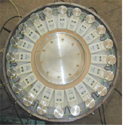
FIGURE 2-12 Top view of 20 units in parallel in an annular LTD cavity. SOURCE: Copied with permission of the first author from M.G. Mazarakis, W.E. Fowler, A.A. Kim, et al., 2009, High current, 0.5-MA, fast, 100-ns, linear transformer driver experiments, Physical Review Special Topics-Accelerators and Beams 12: 050401.
TABLE 2.3 Elements of a Pulsed-Power Inertial Fusion Energy Program
|
|
||
| Phase 1 | Phase 2 | Phase 3 (FTF) |
|
|
||
| MagLif target physics Validate codes LTD technology development Reactor chamber engineering studies Infrastructure planning (targets, etc.) |
Target physics: achieve ignition on a single-pulse facility with repetition-rate-capable pulsed-power technology. RTL engineering studies Establish the viability of a 0.1 Hz, 10-GJ-yield IFE facility through analysis and scaled hydrodynamics experiments. Demonstrate RTL engineering feasibility in burst mode. Design an FTF for pulsed-power IFE. |
Build and test an FTF that operates in burst mode and is capable of achieving breakeven. Achieve multigigajoule yield per pulse. |
|
|
||
of $8 million to $10 million per year if a Technology Readiness Level of 6 (see Chapter 4) by 2018 is to be achieved for many of the elements of the reactor.131
Conclusion 2-11: The promise of MagLIF as a high-efficiency approach to inertial confinement fusion is largely untested, but the program to do so is in place and is funded by NNSA.
Conclusion 2-12: There has been considerable progress in the development of efficient pulsed-power drivers of the type needed for inertial confinement fusion applications, and the funding is in place to continue along that path.
Conclusion 2-13: The physics challenges associated with achieving ignition with pulsed power are being addressed at present as part of the NNSA-sponsored (single-pulse) inertial confinement fusion program.
Recommendation 2-2: Physics issues associated with the Magnetized Liner Inertial Fusion (MagLIF) concept should be addressed in single-pulse mode during the next 5 years so as to determine its scientific feasibility.
__________________________
131 M. Cuneo et al., SNL, “Pulsed Power IFE: Background, Phased R&D, and Roadmap,” Presentation to the committee on April 1, 2011, and M.E. Cuneo et al., SNL, Response to the committee, submitted in March 2011.
Conclusion 2-14: The major technology issues that would have to be resolved in order to make a pulsed-power IFE system feasible—the recyclable transmission line and the ultra-high-yield chamber technology development— are not receiving any significant attention.
Recommendation 2-3: Technical issues associated with the viability of recyclable transmission lines and 0.1 Hz, 10-GJ-yield chambers should be addressed with engineering feasibility studies in the next 5 years in order to assess the technical feasibility of MagLIF as an inertial fusion energy system option.
Assuming the necessary milestones are achieved in both target physics and engineering feasibility, a second phase that would last about 10 more years could be undertaken starting around 2018 to develop the necessary reactor-scale technology and industrial capacity for an FTF.
Some of the necessary technology infrastructure—specifically, production of the recyclable transmission line—may be close enough to standard large-scale industrial manufacturing that development costs and schedule can be projected with reasonable confidence without major demonstration projects. The fact that the cylindrical fusion fuel-containing targets for MagLIF will be inserted into the reactor chamber as part of the recyclable transmission line assembly is a potential simplification compared to other IFE approaches, assuming viable engineering solutions for the line’s fabrication, emplacement, contact, and recycling problems are found.
The MTF has a 3-year target physics program plan using Shiva Star at $2.8 million per year, which is to be followed by explosively driven implosion tests in Nevada at about $100 million per year for 2 years.
Path Forward for Pulsed-Power Inertial Fusion Energy
The plan for pulsed-power IFE that follows is based on information provided to the committee by SNL.
Near Term (≤5 Years, Initially Using NNSA Funding)
- Target physics. Using existing facilities, validate the magnetically imploded cylindrical target concept to the point of achieving scientific breakeven (fusion energy out = energy delivered to the fuel). This requires developing tritium-handling capability on Z. Also, develop IFE target requirements experimentally and theoretically, which requires validating computer codes.
- Pulsed power. Demonstrate the capability of Linear Transformer Driver pulsed-power technology to deliver the necessary power, energy, and
-
repetition rate with a long operational lifetime and the anticipated high efficiency. Design the reactor driver.
- Recyclable transmission line. Develop an engineering design of a recyclable (magnetically insulated) transmission line (RTL) and demonstrate its engineering feasibility experimentally at high power (low repetition rate).
- Reactor chamber. Carry out a detailed design study of the presently favored, multigigajoule, thick-liquid-wall, low-repetition-rate (~0.1 Hz) reactor concept; develop the conceptual design of a credible demonstration power plant in partnership with industry; initiate necessary technology R&D. Design and, if warranted, implement a hydrodynamically equivalent test of the viability of a thick-liquid-wall chamber to contain repeated 10 GJ yield fusion explosions. Determine with industrial partners if such a low-repetition-rate, high-yield system is the optimum solution for pulsed power in light of target physics, recyclable transmission line, and pulsed-power ICF/IFE developments in Phase 1 (Table 2.3).
- Industrial infrastructure planning. In partnership with industry, design production lines and delivery systems needed for RTLs, targets, etc.
- Next facility design. Determine the necessary new facility for ignition experiments (defined as fusion alpha-particle heating of the fuel exceeding energy delivered to the fuel by the driver) and high yield (up to 100 MJ), from which the fusion burn can be scaled to the ~10 GJ yield per target needed by the reactor. (See ZFIRE in the pulsed-power IFE roadmap in Figure 2.13.)
New funding between $8 million and $10 million per year is needed to undertake the last four engineering development tasks.132
Medium Term (5-15 Years, Assumes All Milestones in Phase 1 Are Achieved)
- Target physics: Ignition. Achieve ignition in a new, repetitive-pulse-capable Linear Transformer Driver pulsed-power facility (ZFIRE); fully validate design codes needed to scale to full reactor yield. This would be an NNSA facility that can be used for weapon physics and weapon effects testing.
- Recyclable transmission line engineering. Demonstrate operation of an RTL at ~100 TW and 0.1 Hz (burst mode), with ignition for one or more “single pulses.”
- Reactor chamber. Establish by analysis and demonstrate key technologies associated with the thick liquid wall IFE reactor chamber needed for ~10 GJ, 0.1 Hz operation (vacuum system, liquid wall recovery, and so on). This technology could also be beneficial for heavy-ion fusion.
__________________________
132 M. Cuneo et al., op. cit.
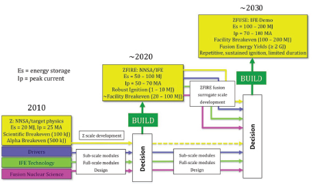
FIGURE 2.13 Pulsed-power roadmap. SOURCE: M.E. Cuneo, M.C. Herrmann, W.A. Stygar, et al., from the document submitted to the committee in response to the committee’s Second Request for Input, p. 6, received March 24, 2011.
- Target design and fabrication for inertial fusion energy. Determine optimized target design and target fabrication requirements for an FTF and a demonstration power plant.
- Fusion Test Facility design. With industry, develop an engineering design for an FTF for pulsed-power fusion, including factories to build RTLs, targets, and other components that must be replaced with each pulse; tritium breeding and handling systems; and all balance-of-plant systems. Design must include full resource requirement and safety and reliability analyses. An economically “competitive” cost of electricity must be projected or this approach cannot go to the demonstration stage.
There are two aspects to the cost of electricity: the amortized capital cost of the plant, the estimate of which is likely to be better than a factor of two only at the end of Phase 2 (see Table 2.3), and the cost of plant operation. Included in the latter is fuel cost, including operation of the tritium recovery system. Let us assume that is the same for all of the potential reactors. The dominant additional operating cost for pulsed-power fusion energy is likely to be manufacturing and recycling the RTLs. At present it is not known how that will compare with, for example, the actual
costs incurred by laser-driven systems for replacing optical components or heavy-ion fusion for replacing final focusing magnets. This kind of operating cost will not be known very well until the end of Phase 2 for any of the approaches to IFE.
Long Term (>20 Years): Build and Operate a Fusion Test Facility
Assuming all milestones in the medium-term program are met, an FTF would be designed to achieve facility breakeven in initial operation (fusion yield of 100-200 MJ) in repetitive pulse operation but for “bursts” of limited duration. Upgrades would enable this facility to increase its yield to ~2 GJ or more. It is too early to provide a credible estimate for the cost of an FTF (see ZFUSE in the Roadmap, below) as the cost of the reactor chamber and recyclable transmission line factory are likely to be dominant and they will not be established until the end of Phase 2.
A conceptual roadmap for implementing the R&D program for pulsed power inertial fusion is shown in Figure 2.13.
There are a number of technical approaches, each involving a different combination of driver, target, and chamber, that show promise for leading to a viable IFE power plant. These approaches involve three kinds of targets: indirect drive, direct drive, and magnetized target. In addition, the chamber may have a solid or a thick-liquid first wall that faces the fusion fuel explosion, as discussed in Chapter 3.
Substantial progress has been made in the last 10 years in advancing most of the elements of these approaches, despite erratic funding for some programs. Nonetheless, substantial amount of R&D will be required to show that any particular combination of driver, target, and chamber would meet the requirements for a demonstration power plant.
In all cases, the drivers may build on decades of research in their area. In all technical approaches there is the need to build a reactor-scale driver module for use in an FTF. The timing for this step is discussed in Chapter 4.
As discussed in Chapter 4, development of an FTF and the upgrade to a demonstration plant requires an integrated system engineering approach supported by R&D at each stage. This statement is true regardless of which driver-target combination is chosen. It also requires involvement and support from the user community (utilities), from the facilities engineering community (large engineering firms), and the government (national laboratories) to conduct R&D and risk reduction programs for laser drivers, target physics, target manufacturing and commissioning, reactors, and balance-of-plant systems. In addition, work must address licensing and environmental and safety issues.


