
Inertial Fusion Energy Technologies
This chapter deals with the technologies other than the driver technologies covered in Chapter 2 that are required to produce and utilize the energy from fusion nuclear reactions in an inertial fusion energy (IFE) system. The first sections in this chapter cover the targets, chambers, related materials issues, as well as tritium production and recovery. Subsequent sections cover crosscutting issues of environment, health, and safety as well as balance-of-plant and economic considerations.
In addition to target science, there are challenges for IFE embedded in what is usually labeled “technology” (e.g., chambers): These challenges involve a broad range of scientific disciplines, including nuclear and atomic physics, materials and surface science, and many aspects of engineering science. In the next several years, however, IFE research will be involved not in engineering developments, but rather in science and engineering research aimed at determining whether feasible solutions exist to very challenging “technology” problems.
An effort is needed to determine whether there is any IFE concept (where “concept” means some combination of target type, driver, and chamber) that appears to be feasible. Only certain combinations of targets, drivers, and chambers seem to be workable. While the emphasis today and in the near future should be on target performance, working exclusively on problems associated with target performance could easily lead to solutions that are not compatible with practical driver and chamber options. Such a serial approach could lead to dead ends and could also extend the time it takes to arrive at practical applications of IFE. For each technological approach, the committee identifies a series of critical R&D objectives that
must be met for that approach to be viable. If these objectives cannot be met, then other approaches will need to be considered.
The approach used in the High Average Power Laser (HAPL) program (see Chapter 1) was one in which all the potential feasibility issues of the entire IFE system were studied, and then the most important ones were addressed to try to find basic solutions. It is a good example of how a national IFE program might be structured.
HIGH-LEVEL CONCLUSIONS AND RECOMMENDATIONS
The main high-level conclusions and recommendations from this chapter are given below.
Conclusions
Conclusion 3-1: Technology issues—for example, chamber materials damage and target fabrication and injection—can have major impacts on the basic feasibility and attractiveness of IFE and thus on the direction of IFE development.
Conclusion 3-2: At this time, there appear to be no insurmountable fusion technology barriers to realizing the components of an IFE system, although knowledge gaps and large performance uncertainties remain, including those surrounding the performance of the system as a whole.
Conclusion 3-3: Significant IFE technology research and engineering efforts are required to identify and develop solutions for critical technology issues and systems such as targets and target systems; reaction chambers (first wall/blanket/shield); materials development; tritium production, recovery and management systems; environment and safety protection systems; and economic analysis.
Recommendations
Recommendation 3-1: Fusion technology development should be an important part of a national IFE program to supplement research in IFE science and engineering.
Recommendation 3-2: The national inertial fusion energy technology effort should leverage materials and technology development from magnetic fusion energy efforts in the United States and abroad. Examples include ITER’s test blanket module R&D program, materials development, plasma-facing components, tritium fuel cycle, remote handling, and fusion safety analysis tools.
TARGET FABRICATION AND HANDLING FOR INERTIAL FUSION ENERGY
Sufficiently rapid fabrication of targets that meet the exacting specifications needed to achieve high gain and an acceptable cost has long been recognized as a key requirement of practical energy application of inertial fusion. All of the earlier National Research Council (NRC) studies on IFE commented on the importance of target fabrication to the success of inertial fusion for energy applications and noted that the prospects for success appear favorable albeit with much work remaining.1 Most of the many IFE power plant design studies have given serious consideration to how the target fabrication requirements could be achieved.2 The consensus of these studies is that with adoption of a limited number of target designs, the selection of mass fabrication techniques, and a development program, the required accuracy and cost goals may be achieved. The R&D needed to make these projections a reality has begun with efforts at General Atomics, the Lawrence Livermore National Laboratory (LLNL) and the University of Rochester. This recent work has focused primarily on laser-driven targets, both direct and indirect drive. Earlier work on ion-beam-driven targets indicates that similar conclusions are expected to hold. Pulsed-power target development is at an early stage, but the
__________________________
1 “Summary of the Findings and Recommendations of the 1986, 1990, and 1997 National Research Council’s Reviews of the Department of Energy’s Inertial Confinement Fusion Program,” Document prepared by NRC staff member E.E. Boyd and provided to the committee on March 2, 2011.
2 For example, see the following: D.T. Goodin, N.B. Alexander, L.C. Brown, et.al., 2005, Demonstrating a target supply for inertial fusion energy, Fusion Science and Technology 47: 1131-1138; D.T. Frey, N.B. Alexander, A.S. Bozek, D.T. Goodin, R.W. Stemke, T.J. Drake, and D. Bitner, 2007, Mass production methods for fabrication of inertial fusion targets, Fusion Science and Technology 51: 786-790; L.R. Foreman, P. Gobby, J. Bartos, et al., 1994, Hohlraum manufacture for inertial confinement fusion, Fusion Technology 26: 696-701; M.J. Monsler and W.R. Meier, 1994, Automated target production for inertial fusion energy, Fusion Technology 26: 873-880; K.D. Wise, T.N. Jackson, N.A. Masnari, et al., 1979, A method for the mass-production of ICF targets, Journal of Nuclear Materials 85-86: 103-106; B.A. Vermillion, J.T. Bousquet, R.E. Andrews, et al., 2007, Development of a new horizontal rotary GDP coater enabling increased production, Fusion Science and Technology 51: 791-794; J.T. Bousquet, J.F. Hund, D.T. Goodin, and N.B. Alexander, 2009, Advancements in glow discharge polymer coatings for mass production, Fusion Science and Technology 55: 446-449; W.S. Rickman and D.T. Goodin, 2003, Cost modeling for fabrication of direct drive inertial fusion energy targets, Fusion Science and Technology 43: 353-358; K.R. Schultz, 1998, Cost effective steps to fusion power: IFE target fabrication, injection and tracking, Journal of Fusion Energy 17: 237-246.
slower repetition rate (~0.1 Hz as opposed to 10 Hz) and the simple target design should ease the challenges of target fabrication for pulsed power. However, much remains to be done for IFE target development for all drivers.
The committee concurs with the conclusion that suitable target fabrication will be possible at an acceptable cost, so that target fabrication is not an obviously insurmountable obstacle for IFE. However, the committee does not endorse the projected target cost numbers any more than it endorses estimates of future costs for any component of IFE technology in the early development stage. The costs could be much higher or lower than estimated in the conceptual studies that have been done. Only a substantial national development effort will provide the validation needed.
When and if ignition is reached, it will be necessary to turn more attention and devote greater resources to target fabrication development. Concepts for producing targets at a rate 100,000 times the rate at which targets are produced today have been developed; therefore, if and when ignition is reached, it would be a good time to determine if the target factory components can be validated with real equipment and if a small, complete factory operating at modest production rates can be built and operated successfully. Such a facility should be accompanied by continued development, begun under the inertial confinement fusion (ICF) program, of physics models of the formation of small hollow spheres, subsequent deuterium-tritium (DT) layering, and other fabrication processes.
Background and Status3
For direct drive, an inertial fusion target consists of a spherical capsule that contains a smooth layer of DT fuel. For indirect drive, the capsule is contained within a metal “hohlraum” that converts the driver energy into X-rays to drive the capsule. These concepts are shown schematically in Figure 3.1. For pulsed-power, target designs vary from those similar to indirect drive, to cylindrical metal shells containing DT. Several examples of IFE targets are shown in Figure 3.2.
Fusion fuel targets must be delivered in a form that meets the stringent requirements of the particular inertial fusion energy scheme, in sufficient quantity and at a low enough cost to supply affordable electricity to the grid. A fusion power plant will consume as many as 1 million targets per day. The allowable target cost will depend on the maximum marketable cost of electricity and the target yield, with estimates for laser and heavy-ion beam systems of 20-40 cents each, based on conceptual modeling studies. For higher-yield, pulsed-power systems, the cost could be proportionately higher. The cost of raw materials for the targets under
__________________________
3 Portions of this discussion are taken from Appendix C of the Department of Energy’s (DOE’s) Fusion Energy Sciences Advisory Committee 1999 report Summary of Opportunities in the Fusion Energy Sciences Program.
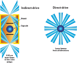
FIGURE 3.1 Indirect-drive and direct-drive IFE target concepts. SOURCE: LLNL.
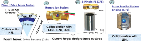
FIGURE 3.2 Examples of IFE targets used with various driver schemes. NRL, Naval Research Laboratory; LANL, Los Alamos National Laboratory, LLNL, Lawrence Livermore National Laboratory, LBNL, Lawrence Berkeley National Laboratory. SOURCE: General Atomics.
consideration currently is at the few-cents-per-target level. Mass manufacturing experience in other industries suggests that these production cost goals are possible, but a development program is required to validate the conceptual modeling studies. Current target production costs and rates are not useful for estimating the costs of mass-produced targets, although the gap between what can be done today and what is needed indicates that target fabrication for IFE plants is a challenge.
The fabrication techniques currently used for inertial confinement fusion (ICF) research targets must meet exacting specifications, have maximum flexibility to accommodate changes in target designs, and provide thorough characterization for each target. Current ICF target fabrication techniques for research targets may not be well suited to economical mass production of IFE targets. Because of the large number of designs and the thorough characterization required for each target, an ICF research target can currently cost thousands of dollars apiece. However, IFE target mass-fabrication studies are encouraging. Fabrication techniques are proposed that are well suited for economic mass production and promise the precision, reliability, and economy needed. However, work has just begun on these techniques.
- Fuel capsules. The capsules must meet stringent specifications including out-of-round (dmax – dmin < 1 μm), wall thickness uniformity (∆w < 0.5 μm), and surface smoothness (<200 Å rms).4 The microencapsulation process, by which tiny particles or droplets are surrounded by a coating, appears well-suited to IFE target production if sphericity and uniformity can be maintained as the capsule size is increased from current 0.5- to 2-mm capsules to the ~5-mm-diameter capsule needed for IFE. Microencapsulation also appears to be suited to the production of foam shells, which are needed for several IFE target designs. Capsule designs for OMEGA experiments and direct-drive IFE power plants are shown in Figure 3.3.
- Hohlraums. ICF hohlraums are currently made by electroplating the hohlraum material, generally gold, onto a mandrel that is then dissolved, leaving the empty hohlraum shell. This technique does not scale up for mass production. Stamping, die-casting, and injection molding, however, do hold promise for IFE hohlraum production.5
- Target assembly. ICF research targets are currently assembled manually using micromanipulators under a microscope. Placement of the capsule at the center of the hohlraum must be accurate to within 25 μm. For IFE, this process must be fully automated, which appears possible. Initial efforts with robotic target assembly and snap-together alignment techniques have shown promising results.6
- Target characterization. Precise target characterization of every research target is needed to prepare the complete “pedigree” required by the ICF experimentalists. Characterization for current research targets is largely
__________________________
4 D. Goodin, General Atomics, “Target Fabrication and Injection Challenges in Developing an IFE Reactor,” Presentation to the committee on January 30, 2011.
5 A. Nikroo, General Atomics, “Technical Feasibility of Target Manufacturing,” Presentation to the committee on July 7, 2011.
6 A. Nikroo, during a site visit to General Atomics on February 22, 2012.
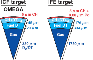
FIGURE 3.3 Direct-drive target capsules. SOURCE: University of Rochester.
-
done manually and is laborious. For IFE the target production processes must be sufficiently repeatable and accurate that characterization can be fully automated and used only with statistical sampling of key parameters for process control.
- DT filling and layering. Targets for ICF experiments are filled by permeation, and a uniform DT ice layer is formed by “beta layering.” Using very precise temperature control, excellent layer thickness uniformity and surface smoothness of about 1 μm rms can be achieved.7 These processes are suited to IFE, although the long fill and layering times needed may result in large (up to ~10 kg) tritium inventories. Advanced techniques, such as liquid wicking into a foam shell, could greatly reduce this amount. These processes are improving but remain far short of the level of reproducibility that a reactor would require. If IFE targets need DT ice smoothness of better than ~1 μm to achieve high gain, new layering techniques will be needed.
- Target handling and injection. IFE targets will be injected into the target chamber at rates as high as ~10-20 Hz. The targets must have adequate
__________________________
7 D. Goodin, General Atomics, “Target Fabrication and Injection Challenges in Developing an IFE Reactor,” Presentation to the committee on January 30, 2011.
thermal and mechanical robustness and protection, such as hohlraums or sabots, to survive the injection and in-chamber flight. This solution must also be compatible with the chamber protection and energy recovery schemes (see the next section, “Scientific and Engineering Challenges and R&D Priorities.”).
ICF research targets that meet all current specifications for both laser direct and indirect drive have been fabricated and fielded in small quantities, including the uniform, smooth DT ice layer. ICF research targets currently cost thousands of dollars apiece on average, but the costs vary widely; simple production targets can cost many times less, and targets requiring significant development effort could cost many times more than that amount. For a power plant, a significant transition needs to be undertaken using low-cost, high-throughput manufacturing techniques, along with large batch sizes for any chemical processes, as well as likely use of statistical characterization. Many of the processes used for current target fabrication do not scale well to mass production and will need to be replaced. Examples are die-casting arrays of hohlraum parts instead of diamond turning a mandrel for gold plating, and the use of large-batch chemical vapor deposition (CVD) diamond coaters for the ablators and membranes instead of the small size bounce-pan coaters now used. The HAPL program, led by the Naval Research Laboratory (NRL), which went well beyond laser drivers to consider all aspects of IFE power by laser direct drive, and the Laser Inertial Fusion Energy (LIFE) program, led by LLNL, which focuses on IFE by laser indirect drive, have begun evaluation and selection of mass production methods that can meet IFE requirements. The termination of the HAPL program has slowed this effort.
There have been successful efforts to develop several IFE target mass production techniques. To make thick-walled polymer capsules, a poly-alpha-methyl-styrene (PAMS) mandrel is made by microencapsulation and then coated with glow discharge polymer (GDP). A rotary kiln version of the GDP coater has been made that is capable of mass production, but it has not been used enough to demonstrate that it can meet the surface roughness specification.8 In the HAPL program,9 foam shells were made that met the HAPL target specification with appreciable yield using microencapsulation droplet generators. Applying a smooth, gastight overcoat to these foam shells was the focus of development at the time that the HAPL program ended. A cryogenic fluidized bed for layering deuterium in direct-drive targets was built in the HAPL program. It was successfully operated at cryogenic
__________________________
8 A. Nikroo, General Atomics, “Technical Feasibility of Target Manufacturing,” Presentation to the committee on July 7, 2011.
9 J.D. Sethian, D.G. Colombant, J.L. Giuliani, et al., 2010, The science and technologies for fusion energy with lasers and direct-drive targets, IEEE Transactions on Plasma Science 38 (4): 690-703.
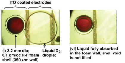
FIGURE 3.4 Electric-field-mediated microfluidics (“lab-on-a-chip”) wicking of cryogenic D2 into a foam capsule target. ITO, indium tin oxide. SOURCE: University of Rochester.
temperatures using empty capsules but has yet to be operated with deuterium-filled capsules. General Atomics has built a robotic target assembly station based on commercially available industrial robots. This station has glued together cone-in-shell targets suitable for fast ignition experiments10 such that the virtual cone tip coincides with the capsule center to within the specification of 10 μm. LLNL is developing target assembly techniques for the National Ignition Facility’s (NIF’s) National Ignition Campaign (NIC) that facilitate target component self-alignment (“snap-together” assembly), which will be useful for IFE target assembly. Development of the process for manufacturing hohlraum parts made of lead by cold forging (or stamping) started recently. Some development of die-casting hohlraum parts is also expected to begin soon.11 Innovative concepts such as the University of Rochester’s use of electric-field mediated microfluidics (lab-on-a-chip),12 shown in Figure 3.4, may allow higher quality at lower cost. In summary, progress has been made on IFE target fabrication, creating many opportunities for improved materials and technologies, but much remains to be done.
__________________________
10 A. Nikroo, during a site visit to General Atomics on February 22, 2012.
11 A. Nikroo, General Atomics, “Technical Feasibility of Target Manufacturing,” Presentation to the committee on July 7, 2011.
12 D.R. Harding, T.B. Jones, Z. Bei, W. Wang, S.H. Chen, R.Q. Gram, M. Moynihan, and G. Randall, 2010, Microfluidic Methods for Producing Millimeter-Size Fuel Capsules for Inertial Fusion, Materials Research Society Fall Meeting, Boston, Mass.
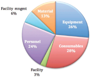
FIGURE 3.5 Cost breakout for target mass manufacture, based on a representative factory model (example shown for LIFE targets). SOURCE: R. Miles, J. Biener, S. Kucheyev, et al., 2008, “LIFE Target Fabrication Research Plan,” LLNL-TR-408722.
To estimate possible costs, factory models have been constructed based on experience from the chemical batch processing industry combined with in-house expertise at General Atomics and LLNL. These models considered likely manufacturing and assembly equipment types, factory build costs, personnel and operational costs, and in-process volumes, among other things, and amortized the integrated costs over the volume of targets produced. Predictions ranged from 17 to 35 cents per target.13 A breakout of projected target costs based on a target factory economics model is shown in Figure 3.5.
Conclusion 3-4: Target fabrication at the quality and production rate needed appears possible with continued development.
__________________________
13 See, for example, D.T. Goodin, A. Nobile, J. Hoffer, et al., 2003, Addressing the issues of target fabrication and injection of inertial fusion energy, Fusion Engineering and Design 69: 803-806; R. Miles, et al., 2009, “LIFE Target Fabrication Costs,” LLNL-TR-416932; and R. Miles, J. Biener, S. Kucheyev, et al., 2008, “LIFE Target Fabrication Research Plan,” LLNL-TR-408722.
Scientific and Engineering Challenges and R&D Priorities
Target Fabrication
The scientific challenges to IFE target fabrication lie primarily in understanding the physics behind the specifications for inertial fusion target requirements: sphericity, uniformity and smoothness (How good is good enough?), and understanding the physics and chemistry behind the ability to achieve those requirements (Which physical processes control sphericity, uniformity, and smoothness?) Experiments with IFE targets at the NIF can help provide the physics understanding. The engineering challenges lie in selecting and developing materials that can achieve these requirements and in developing the processes and equipment needed to do so reliably and repeatedly with very high yield at reasonable cost.
The specific requirements appear at present to include these:
• The ability to fabricate IFE targets that meet specifications such as those for indirect drive:
— Capsules with 4 mm diameter, <1 μm sphericity, ~100 μm wall with <0.5 μm Aw, <200 Å rms surface smoothness, and a surface power spectrum below the NIF capsule profile.
— Hohlraums fabricated to ≤10 μm accuracy. Targets assembled to ≤10 μm accuracy.
and those for direct drive:
— Foam shell capsules with ~150 μm thick with <0.5 μm ∆w and ~4 mm diameter with <1 μm sphericity. Foam density <100 mg/cm3 with cell size <1 μm. A seal coat14 on top of the capsule having a 1-5 μm wall with <0.5 μm ∆w, <200 Å rms surface smoothness, and a surface power spectrum meeting the NIF/NIC required profile.
• A projected cost of mass-producing IFE targets for a power plant of ≤$0.50 each.
The objectives of IFE target fabrication R&D must be to understand the physics behind the specifications for inertial fusion target requirements and understand the physics behind the ability to achieve those requirements to such a depth that
__________________________
14 The seal coat surface for the direct drive capsule both seals the capsule and facilitates its injection into the target chamber without going out of specification by the time it reaches the center.
target materials can be selected and/or developed that meet target specifications, and processes and equipment can be developed to do so reliably and repeatedly with very high yield at reasonable cost.
Target Injection at High Repetition Rates
After the targets have been fabricated they must be injected into the chamber. For laser drivers and accelerators, several methods of ballistic injection have been suggested, including gas guns and electromagnetic accelerators. For present pulsed-power fusion system designs, the targets are attached directly to the end of a transmission line. In this case, the targets and a replaceable transmission line are inserted into the chamber mechanically. Here, the committee considers only ballistic injection.
Gas guns have been built at LBNL and at General Atomics (Figure 3.6). These have been used to accelerate surrogate targets to high velocity (>100 m/s). In the case of direct drive, the targets must be carried by some kind of sabot to protect the target as it is accelerated in the gun barrel and injected into the chamber. The
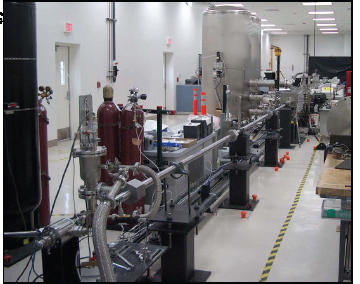
FIGURE 3.6 Inertial fusion energy target gas-gun injection experiment. SOURCE: General Atomics.
sabot is removed either mechanically (with a spring) or magnetically. The gas gun experiments have demonstrated high-repetition-rate injection, including separation of the sabots from the targets, in a burst mode.15 In these experiments, the placement accuracy at a distance of 20 m was about 10 mm. This 10 mm includes the contributions from the accuracy of the gun and from the separation of the target from the sabot. Estimates of the placement accuracy for indirectly driven targets (no sabots required) are much better than 10 mm. This is adequate for subsequent target tracking and beam steering, as discussed in the next section.
In summary, one can unquestionably build devices to inject the targets at adequate velocities and repetition rates. The remaining challenges are associated with wear and long-term reliability and durability, particularly in a fusion environment.
Conclusion 3-5: Target injection techniques have been developed in the laboratory that are adequate for subsequent target tracking and steering and that appear to be scalable to meet the inertial fusion energy requirements for speed and accuracy.
Target Tracking and Driver Pointing
The uncertainty in position of the targets when injected is much larger than the alignment precision of the driver beams relative to the target needed for ignition. Typically the required alignment precision is approximately 20 μm for both laser and ion direct drive.16 For NIF-like, indirectly driven targets, the required precision is approximately 80 μm. For ion-beam indirect drive, the requirement is calculated to be 100 to 200 μm, depending on the size of the hohlraum. Given this situation, it is necessary to track the position of the target and to point the driver beams at the target. At least two methods of target tracking have been demonstrated. One tracks the shadow of the target using light-sensitive sensors. The other relies on the reflection (“glint”) off the target. A scaled experiment performed by the University of California at San Diego and General Atomics demonstrated a beam alignment of 28 μm.17 An alignment precision of 28 μm is nearly good enough, even for direct drive. Improvement to 20 μm seems possible, although shock-ignition targets may require still more precise alignment. The remaining challenge is to scale the technique to full size and full target velocity and demonstrate that it works reliably in a fusion environment. In a fusion environment one will undoubtedly have to
__________________________
15 D.T. Goodin, A. Nobile, J. Hoffer, et al., 2003, Addressing the issues of target fabrication and injection of inertial fusion energy, Fusion Engineering and Design 69: 803-806.
16 L.C. Carlson, M.S. Tillack, J. Stromsoe, et al., 2010, Completing the viability demonstration of direct-drive IFE target engagement and assessing scalability to a full-scale power plan, IEEE Transactions on Plasma Science 38 (3): 300-305.
17 Ibid.
deal with rapidly changing temperatures, mechanical vibration, and degradation of components by radiation.
The pointing of laser beams is usually done mechanically using a rapidly moving optical element. For accelerators, the beams can be pointed by pulsing relatively weak dipole magnets. For the beam parameters usually associated with ion indirect drive, this technique does not appear to be challenging. On the other hand, it may be necessary to put a significant energy spread on the ion beams to achieve the beam pulse durations needed for shock ignition or fast ignition. Energy spread produces dispersive effects in magnetic fields, so more work is needed to establish pointing feasibility for these options.
Conclusion 3-6: Target tracking and laser-beam-pointing methods that are adequate for indirect drive have been developed in the laboratory; direct drive will require higher precision.
Target Survival Under Hostile Conditions
The targets must survive injection into the target chamber and retain their precise dimensions, surface finish, and other characteristics until they are ignited by the driver beams. The insults they may sustain include acceleration in a gun, separation from a sabot, thermal radiation loads from the chamber walls, thermal and aerodynamic loads from residual gas in the chamber, and condensation of residual gas on the cryogenic target. The conditions are very challenging.
All high-gain target designs require cryogenic solid or liquid fuel and must remain at low temperature (<20 K) until they are fired. In contrast, the temperature of the chamber wall might be approximately 800 K, and the temperature of any gas in the chamber could be much higher. Indirectly driven fuel capsules are protected and insulated by the hohlraum. Numerical simulations indicate that these fuel capsules will survive even if there is significant gas in the chamber. Consequently, the LIFE power plant study, based on indirect drive, adopts gas wall protection. The chamber is designed to contain about 6 mg/cm3 of Xe to protect the first wall and optical elements from photons and other target debris. Directly driven targets could not survive in such an environment, so the chambers chosen for these targets are usually designed to operate at chamber gas densities that are typically about three orders of magnitude lower. Under these lower-pressure conditions, calculations and some experiments indicate that the targets will survive at achievable injection velocities, even if the sabot carrying the target is stripped from the target as the target leaves the barrel of the injector and enters the chamber.18 The implications
__________________________
18 J.D. Sethian, NRL, “Integrated Design of a Laser Fusion Target Chamber System,” Presentation to committee on June 15, 2011.
for chamber design are discussed in the next section, entitled Chamber Technology. If it turns out to be highly desirable to have some kind of gas or liquid wall protection, it may be possible to delay the separation of the target and sabot until the target is very near the center of the chamber. In all cases, continued development of concepts and more experimental verification of target survivability in the expected chamber environment are needed.
Finally, the survivability issues for indirectly driven heavy-ion fusion and pulsed-power fusion appear to be less serious than the corresponding issues for laser fusion. Ion beams can penetrate the hohlraum wall so no laser entrance holes are required. For pulsed-power fusion, the target is usually part of a relatively massive transmission line that is placed into the chamber.
Conclusion 3-7: Analysis of target survival during injection into the target chamber indicates that survival of indirect-drive targets appears to be feasible. Further combined development of target and associated chamber systems will be needed to assure survival of direct-drive targets.
Recycling of Target Materials
All targets produce radioactive materials—unburned DT fuel if nothing else— that must be recycled. Nevertheless, targets for laser direct drive produce orders-of-magnitude less high-Z material than indirectly driven targets for both lasers and ion beams. Although the indirectly driven targets have the advantage in terms of injection, direct drive has the advantage in terms of recycling. Most direct-drive (actually mixed-drive) ion targets also contain significant quantities of higher-Z material. In the case of pulsed-power fusion, the target materials themselves are dwarfed by the transmission line structure that is destroyed on each pulse.
There is currently little agreement on how to handle the high-Z materials such as Pb, Au, and Pd. These materials will be activated to some extent and will have to be considered as radioactive waste. Some researchers believe that it is preferable to use new material, such as lead, for each target.19 In this case, there is a significant waste stream but it is only mildly radioactive. In contrast, the LIFE team proposes to recycle the lead used for the hohlraums.20 All surfaces in the reactor and vacuum chamber are designed to operate at temperatures exceeding the melting point of lead. The molten lead is collected and recycled. For liquid-wall chambers using
__________________________
19 L.A. El-Guebaly, P. Wilson, and D. Paige, 2006, Evolution of clearance standards and implications for radwaste management of fusion power plants, Fusion Science and Technology 49: 62-73.
20 M. Dunne, E.I. Moses, P. Amendt, et al., 2011, Timely delivery of laser inertial fusion energy (LIFE), Fusion Science and Technology 60: 19-27; and J.F. Latkowski, R.P. Abbott, S. Aceves, et al., 2011, Chamber design for the laser inertial fusion energy (LIFE) engine, Fusion Science and Technology 60:54-60.
lithium or molten salt, the hohlraum materials would have to be removed from the liquid. There are a number of trade-offs involved in the choice of hohlraum material. Some materials are better than others in terms of target performance. Some are better in terms of activation, toxicity, and cost. Finally, some are easier to separate from the chamber liquid.
For IFE concepts with wetted or liquid wall chambers, it may be possible to make the targets from materials that are constituents of the chamber coolant. Lead hohlraums for use with LiPb coolants and frozen-salt hohlraums with a high-Z liner for use with liquid-salt coolants may be possible.
There has been significant research on nearly all of the issues associated with handling and recycling the target materials.21 Determining the optimal methods and materials and demonstrating commercial feasibility remains an important challenge. Many of the topics associated with the recycling of tritium and other target materials will be discussed later in this chapter.
Conclusion 3-8: Target materials recycling issues depend strongly on the inertial fusion energy concept, the target design, and the chamber technology. Direct-drive targets have fewer concerns in the area of recycling and waste management; indirect-drive target materials handling, recycling, and waste management will need further development.
Path Forward
Each inertial fusion concept—direct-drive lasers, indirect-drive lasers, heavy ion beams, and pulsed power—will require its own specific target. Each of these will require target fabrication techniques for mass production. The targets for each IFE concept may have different materials and characteristics for injection, tracking and survival in the target chamber. While there may be some opportunities for synergy between different target technologies, the following R&D steps will be required for each inertial fusion concept.
Near Term (<5 Years)
- Work with target designers to jointly agree on designs that promise high gain, practical fabrication, good mechanical strength, and good thermal robustness.
- Continue development, begun under the ICF program, of physics models of the formation of small hollow spheres, subsequent DT layering, and other fabrication processes.
__________________________
21 L.A. El-Guebaly, P. Wilson, and D. Paige, 2006, Evolution of clearance standards and implications for radwaste management of fusion power plants, Fusion Science and Technology 49: 62-73
- Demonstrate gain using prototype targets made of commercial IFE materials with expected fabrication specifications and tolerances on the NIF.
- Quantify detailed target requirements and manufacturing tolerances.
- Select and demonstrate target fabrication techniques for low-cost mass production.
- Develop characterization and statistical sampling techniques needed for IFE mass production.
- Demonstrate DT filling and layering/wicking protocols suitable for IFE targets.
- Develop an IFE target factory conceptual design and cost estimate. Conceptualize a target factory test facility with single units of small machines, leading to a target factory with multiple units of larger machines of similar design.
- Continue laboratory-scale development of target injection and tracking techniques, including studies of target survival during injection and transport into a simulated target chamber.
- Investigate target materials recycle and waste management issues.
Medium Term (~5-15 Years)
- Test IFE target concepts in the NIF; determine sensitivity to target fabrication parameters and tolerances.
- Design a target factory and injection and tracking system to supply targets to the first IFE demonstration facility.
- Put in place target material recycling and/or waste stream management processes.
Long Term (>15 Years)
- Develop the technologies for construction of a commercial target factory for an IFE power plant.
- Update techniques and factories for the mass fabrication of targets to reflect the latest target designs.
Conclusion 3-9: An inertial fusion energy program would require an expanded effort on target fabrication, injection, tracking, survivability, and recycling. Target technologies developed in the laboratory would need to be demonstrated on industrial mass production equipment. A target technology program would be required for all promising inertial fusion energy options, consistent with budgetary constraints.
Background and Status
An IFE system will require the means to extract and utilize the energy produced by the fusion events that take place inside the reaction chamber; the ability to breed, extract, and process the tritium fuel; and the ability to maintain these systems in a timely manner. The systems must allow for delivery of the driver energy to the target and must ensure that the chamber can withstand the target emissions over timescales of a year or more. All this must be done in a way that meets the safety and environmental goals for a commercial energy system.
This section discusses the issues, challenges, and R&D needed for chamber options for IFE while other sections in this chapter discuss the related issues of materials, tritium systems, and safety and environmental topics.
A number of IFE design studies have been carried out that, while preliminary, shed light on the key features of the chambers of IFE systems. These include the OSIRIS/SOMBRERO22 and Prometheus23 studies that developed reactor designs for laser and heavy-ion drivers. There are also other studies on heavy-ion chambers from HIBALL,24 HYLIFE,25 and the Robust Point Design and Hylife-II studies,26 while information on pulsed-power reactors has also been reviewed.27 The most recent design efforts are the HAPL direct drive laser design28 and the LIFE indirect-drive laser design.29 The information that follows in this section is a composite of the information in these references.
__________________________
22 DOE, 1992, OSIRIS and SOMBRERO Inertial Fusion Power Plant Designs, DOE/ER-54100-1.
23 DOE, 1992, Inertial Fusion Energy Reactor Design Studies Prometheus-L and Prometheus-H, DOE/ER-54101.
24 B. Badger, K. Beckert, R. Bock, et al., 1981, HIBALL—A Conceptual Heavy Ion Beam Fusion Reactor Study, UWFDM-450, University of Wisconsin at Madison, and KFK-3202, Kernforschungszentrum Karlsruhe.
25 J.A. Blink, W.J. Hogan, J. Hovingh, W.R. Meier, and J.H. Pitts, 1985, The High Yield Lithium Injection Fusion Energy (HYLIFE) Reactor, UCRL-53559, LLNL.
26 S.S.Yu, W.R. Meier, R.P. Abbott, et al., 2003, An updated point design for heavy ion fusion, Fusion Science and Technology 44(2): 266-273.
27 See C.L. Olson, 2005, “Z-Pinch Inertial Fusion Energy,” Landolt-Boernstein Handbook on Energy Technologies, VIII/3: 495-526, Springer-Verlag, Berlin; and G.E. Rochau and C.W. Morrow, 2004, A Concept for a Z-Pinch Driven Fusion Power Plant, SAND2004-1180.
28 J.D. Sethian, D.G. Colombant, J.L. Giuliani, et al., 2010, The science and technologies for fusion energy with lasers and direct-drive targets, IEEE Transactions on Plasma Science 38(4): 690-703.
29 M. Dunne, E.I. Moses, P. Amendt, et al., 2011, Timely delivery of laser inertial fusion energy (LIFE), Fusion Science and Technology 60: 19-27; and J.F. Latkowski, R.P. Abbott, S. Aceves, et al., 2011, Chamber design for the laser inertial fusion energy (LIFE) engine, Fusion Science and Technology 60:54-60.
The technology for the reactor chambers, including heat exhaust and management of tritium, involves difficult and complicated issues with multiple, frequently competing goals and requirements. Understanding the issues and the options for resolution is important for establishing that credible pathways exist for the commercialization of IFE, and this will require significant effort. Understanding the performance at the level of subsystems such as a breeding blanket and tritium management, and integrating these complex subsystems into a robust and self-consistent design will be very challenging.
The two main classes of reaction chamber are those with solid walls and those with liquid walls. The key feature of liquid wall chambers is the use of a renewable liquid layer to protect chamber structures from target emissions. Two primary options have been proposed and studied: wetted-wall chambers and thick liquid-wall chambers.
With wetted-wall designs, a thin layer of liquid on the inside of the wall shields the structural first wall from most short-range target emissions (X-rays, ions, and debris) but not neutrons. Various schemes have been proposed to establish and renew the liquid layer between shots, including flow-guiding porous fabrics, porous rigid structures and thin film flows. Similarly, various schemes have been proposed to protect beam ports and final optics. The thin liquid layer can be the tritium-breeding material (e.g., FLiBe, PbLi, or Li) or another liquid such as molten Pb. Such thin layers will contribute to tritium breeding, but not significantly.
With thick-liquid-wall designs, liquid jets are injected by stationary or oscillating nozzles to form a neutronically thick layer (typically with an effective thickness of ~50 cm) of liquid between the target and first structural wall. Gaps are provided between the thick liquid flows for access by the driver beams. This is much easier to accomplish for indirect drive, which can have a biaxial or even uniaxial beam geometry, than for direct drive, which requires many driver beams to achieve drive symmetry. In addition to absorbing short-range emissions, the thick liquid layer degrades the neutron flux and energy reaching the solid material first wall, so that the structural walls may survive for the life of the plant (~30-60 yr). The thick liquid serves as the primary coolant and tritium breeding material. In essence, the thick liquid wall places the fusion blanket inside the first wall instead of behind the first wall. A significant potential advantage of thick liquid wall designs is that the neutron damage to chamber structures can be reduced considerably due to the shielding provided by the liquid. This allows for a reduction of the waste stream as the need for replacement of the chamber structures can be minimized, resulting in a simplification of the waste management requirements and improving availability. An example is shown in Figure 3.7, where the target and driver beams enter the chamber biaxially between thick liquid flows. It is also possible, in principle, to have centrifugally maintained thick liquid walls.
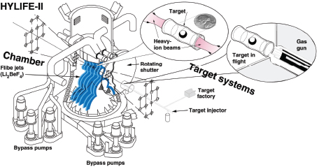
FIGURE 3.7 Thick-liquid-wall chamber for heavy ion fusion. SOURCE: LBNL.
Solid- or dry-wall chambers are expected to be compatible with laser-beam or ion-beam entrance into the chamber. If the dry wall chamber is evacuated or has a gas fill of no more than a few tens of millitorrs (at room temperature), then it may be possible to have easier target injection, target tracking, target survival, high-fidelity laser propagation, restoration of chamber conditions for the next shot, and gas reprocessing (e.g., cooling and target debris removal).
Dry-wall chambers, which have no constraints for liquid film or liquid jet geometry, should be able to accommodate the illumination geometry for either direct-drive or indirect-drive targets. For laser drivers, chamber designs have been proposed to deal with target emission from either direct-drive (e.g., HAPL30) or indirect-drive (e.g., LIFE31) targets. An example is shown on Figure 3.8.
Wetted-wall chambers could be compatible with either direct-drive or indirect-drive illumination, but there are some advantages to indirect drive since it would be possible to configure the beam paths from the sides and this could reduce the chance of liquid reaching the final optics. The thin liquid layer would be able to withstand short-range ion, X-ray, and debris emissions from either direct-drive or indirect-drive targets.
__________________________
30 J.D. Sethian, D.G. Colombant, J.L. Giuliani, et al., 2010, The science and technologies for fusion energy with lasers and direct-drive targets, IEEE Transactions on Plasma Science 38(4): 690-703.
31 M. Dunne, E.I. Moses, P. Amendt, et al., 2011, Timely delivery of laser inertial fusion energy (LIFE), Fusion Science and Technology 60: 19-27.
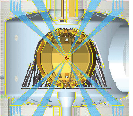
FIGURE 3.8 Example of a dry-wall chamber concept developed for the LIFE project. SOURCE: M. Dunne, E.I. Moses, P. Amendt, et al., 2011, Timely delivery of laser inertial fusion energy (LIFE), Fusion Science and Technology 60: 19-27.
There are additional issues associated with the incorporation of liquids into the reaction chamber. Thick liquid walls are likely only compatible with indirect-drive targets unless extraordinary measures are taken to provide a thick shielding region between up to hundreds of beam paths. The thick liquid layer should withstand the energy pulse of the target emissions. Indirect drive and magnetically driven direct drive with thick liquid wall chambers would be the primary choices at present for heavy-ion and pulsed-power drivers, respectively.
It is important to note that the pulse repetition rates very much affect the chamber issues. Such rates vary from 16 Hz for some laser drivers, to around 5 Hz for heavy ion driver concepts, and to about 0.1 Hz for pulsed power concepts. For
example, increased repetition rates imply higher target injection speeds that can increase the heat load to the cryogenic targets in gas-filled chambers. Increased repetition rates will also mean less time to clear the chamber for the next shot and may nessecitate larger pumping ports. Higher rates also reduce the time available for cooling of the chamber gas between shots.
All fusion concepts, both IFE and MFE, must provide for tritium self-sufficiency in order to have a closed fuel cycle needed for commercial success or even large-scale test facilities. This covers a range of issues, including performance of the target (especially the tritium burnup fraction), the tritium breeding potential of the blanket, tritium recovery and storage, and tritium inventories, including tritium hold-up in the walls of the chamber. These issues are discussed in more detail in the following section on tritium production, recovery, and management. In general, IFE will greatly benefit from the long experience and large investments being made in the worldwide MFE program on tritium breeding and handling.
IFE has a potentially advantageous feature in that the driver system and chamber system are not necessarily closely connected together. Furthermore, it appears to be possible to take advantage of the modular nature of at least some of the driver candidates. These features offer potential benefits in terms of plant maintenance and availability. Further, this decoupling and ability to test modular components without building the entire reactor system should reduce the cost and the time needed to qualify IFE components. For the chamber, periodic replacement or repair would be undertaken—hopefully, only every few years.
These considerations lead to the following conclusion:
Conclusion 3-10: The chamber and blanket are critical elements of an inertial fusion energy power plant, providing the means to convert the energy released in fusion reactions into useful applications as well as the means to breed the tritium fuel. The choice and design of chamber technologies are strongly coupled to the choice and design of driver and target technologies. A coordinated development program is needed.
Scientific and Engineering Challenges and Future R&D Priorities
There are, in general, significant threats to IFE chambers, particularly for those concepts that utilize solid walls. These threats include surface blistering and exfoliation due to ion implantation, near-surface ion and thermal damage, dust creation and material redeposition, cyclic thermomechanical stresses, volumetric fusion neutron and gamma-ray damage, and nuclear heating. Some of these issues are similar to those faced by MFE concepts, although the inherent pulsed nature of IFE poses unique challenges. Of special concern to IFE laser concepts is the damage
to laser system final optics. These issues are discussed in more detail in the next section, Path Forward.
The key challenge for a dry-wall concept is to establish a configuration that can repeatedly withstand the typically 300 million high-energy pulses per year of X-rays, ions, and neutrons coming from the target. This threat spectrum depends on the target design. For almost all IFE targets, roughly 70 percent of the fusion energy is released as neutrons. For a direct-drive target, typically 28 percent comes out in ions and 2 percent in X-rays. For an indirect-drive target, the non-neutron ratio is roughly inverted: 25 percent comes out in X-rays and 5 percent in ions.
The basic requirements for the chamber to operate at the necessary pulse repetition rates (which can vary from ~10 Hz to 0.1 Hz) are, after each shot:
- Reestablish chamber conditions that allow for the delivery of the target with the required precision and without damaging the integrity of the target.
- Reestablish chamber conditions that allow for delivery of the driver energy to the target including high-repetition-rate target tracking and beam pointing for lasers and heavy ion drivers.
- Reestablish in-chamber conditions that may be used to protect chamber structures from target emissions (e.g., liquid films, liquid jets, and gases) and/or assure survival of the first wall subjected to pulsed energy loads.
For dry-wall chambers, an important issue is target heating during injection due to thermal radiation from the hot chamber wall. There may also be some residual target materials and potential gas propellant from previous shots in the chamber that could add to target heating and affect its trajectory. The use of infrared reflective coatings and/or protective sabots on the target may reduce heating by the wall. For gas-filled chambers, the gas fill dominates in-chamber conditions and will have a greater impact on target heating and trajectory than the walls of evacuated chambers. It will be necessary to limit the gas density and chamber radius to values that allow the target to survive.
For liquid-wall chambers, the liquid vapor filling the chamber contributes to target heating and impacts the trajectory. Liquid drops, if present, must not interfere with target delivery. The protective liquid layers and jets must be reconstituted after the disruptive effects of the target emissions. For pulsed-power concepts, the key issue is the mechanics of delivering the combined recycled transmission line and target system. It will be necessary to reset the liquid sheets to allow subsequent target injection in 1-10 s.
For direct-drive targets (laser or heavy-ion concepts), uniform beam delivery could also be affected by residual vapors, droplet formation, and turbulence from remnant target materials. For laser drivers, the final optics are in direct line of sight of target emissions and thus subject to possible degradation from target debris,
thin-film deposition, and neutron, X-ray, and charged-particle damage. It may be possible to use magnetic deflection of ions to protect the entrance ports and final optics. For gas-filled chambers, the buffer gas may protect the final optics from short-range target emissions. In any event, it will be necessary to choose final optics that are least susceptible to surface perturbation and alignment error.
The first wall is subject to threats from the X-rays and ions. With no gas in the chamber, the X-rays are delivered in very short (a few nanoseconds) pulses. Their energies range from 0.1 to 100 keV, so their penetration depth is 10 to 200 μm, depending on the wall material. The X-rays from direct drive are harder, more penetrating, and less numerous than those expected from indirect drive, so the instantaneous wall temperature rise is lower. The ions, because of their slower velocity, reach the wall several microseconds after the X-rays. In addition, their energy is imparted to the wall on a timescale of a few microseconds, owing to the different energies and species of the ions. The ion spectrum depends on the type of target but will always have the hydrogen isotopes, helium, and carbon as well as the hohlraum species with indirect drive. Generally, the ions deposit their energy and implant within a few microns of the surface, giving a temperature spike and potentially causing first wall material erosion.
Lead is a prime candidate for and example of a particular hohlraum material. It has been selected as both the high-Z and substrate material for indirect-drive targets. Lead has a high opacity to thermal X-rays (thus giving good driver coupling efficiency), is inexpensive and widely available, is compatible with laser beam propagation, and has a favorable melting point and vapor pressure curve that support removal from the chamber. In the LIFE design example, each target contains approximately 3 g of lead, which amounts to a daily throughput of about 4 tonnes. This material would be collected and recycled into future targets. The target chamber xenon fill gas remains sufficiently hot between shots such that the vast majority of lead will remain in the vapor phase. Some of the lead will reach the first wall and blanket structures, where it can condense. Condensed lead will either run down the wall to the debris collection/gas exhaust port at the bottom of the chamber, or it will drip. Gas pumping occurs at the bottom of the fusion chamber. This gas is processed to remove lead, hydrogen isotopes, etc., and is then recompressed for injection into the low-pressure vacuum chamber. Gas injection occurs near the final optics over a relatively small area so that an increased gas velocity is achieved. This gas flow inhibits the flow of particles or droplets to the final optic.
There are more avenues to alleviate the effects of ions than the effects of X-rays, because ions are slower, deposit energy over a longer time, and have an electrical charge that allows them to be diverted. For an indirect drive target, with the much higher fraction of X-rays in the threat spectrum (25 percent vs. 2 percent in direct-drive systems), the volumetric X-ray power deposition is sufficient to melt and possibly even vaporize the chamber wall surface. The timescale for the deposition
energy from these X-rays is much shorter than the energy transport timescale in materials so that all the energy is absorbed in the materials’ surface layers, which leads to repetitive melting and ablation. For example, the surface of a tungsten wall at 10 m radius would be heated to over 6000°C, well past the tungsten melting point, with an indirect-drive target that releases 200 MJ/shot. Thus, any indirect-drive target requires some type of replenishable buffer to protect the solid wall. Options include thin liquids, thick liquids, or a buffer gas. For a direct-drive target, the energy in the X-rays is relatively small, so the X-rays from a 200 MJ target heat up a 10-m-radius tungsten wall to only 1000°C. The ions, when they arrive later over a longer pulse, heat the wall to 1650°C. This is below the melting point of tungsten but still it pushes past the recrystalization temperature and may lead to the formation of cracks.
The dry-wall concepts must also account for the time-averaged power density that requires that the target-facing materials be actively cooled, resulting in thermal stresses in the first wall structure. This may limit the thickness of the chamber facing materials because the surface temperature needs to be lowered before the next pulse to avoid thermal limits at the surface.
Material options for the first wall of solid wall concepts include graphite or SiC composites, as well as refractory metals such as tungsten. Various concepts for engineered materials have been proposed, such as carbon brush structures, tungsten foam, vacuum-sprayed nanoporous tungsten structures, and diffusion-bonded or plasma-sprayed tungsten on ferritic steels.
The use of liquid walls alleviates many of these solid wall concerns but introduces other issues, such as the need to manage vaporization of the liquid and subsequent clearing in the chamber, uniform liquid wetting and refilling at 5-10 Hz, liquid mobility, and the effect of splashing on optics.
Despite the many competing requirements and complicated interactions of the technologies needed for IFE chambers, plausible solutions and self-consistent designs have been put forward for all IFE concepts in the design studies that have been done. Table 3.1 provides a summary and review of the chamber concepts and main issues.
Conclusion 3-11: Chamber and blanket technologies involve a broad range of very challenging and complex interrelated issues rooted in many science and engineering disciplines. Resolving these issues will take a dedicated effort over many years of research and development.
From the scientific and engineering challenges identified in the previous subsection, one can develop a set of demanding R&D objectives that must be addressed for realizing the potential of IFE as an energy system. In general, work on these issues is not being funded at present.
TABLE 3.1 Summary of Inertial Fusion Energy Chamber Concepts and Issues
|
|
|||
| Solid Wall | |||
|
|
|||
| Thick Liquid Wall | Protective Gas | Vacuum | |
|
|
|||
| Heavy Ions (HI) Pulsed Power (Z) | Laser Indirect Drive | Laser Direct Drive | |
|
|
|||
| Primary advantage | Fewer materials issues with X-rays, ions, or neutrons. Thick liquid also breeder/coolant. | Fewer first wall X-ray or ion material issues. | Simplicity. |
| Primary challenge | Chamber clearing, target placement. | Chamber clearing, laser propagation. | First wall resistance to helium retention, surface morphology change, and mass loss. |
| Target survival | Hohlraum thermal insulation. | Hohlraum thermal insulation. | IR protective layer, start target cold. |
| Driver/target coupling | (HI) Accurate target injection. (Z) Target part of RTL: automatically aligned. | Inject target close enough to chamber center to allow laser mirrors to be steered to required accuracy. | Inject target within 1 cm of chamber center, detect glint from target, and steer laser mirror to required accuracy. |
| Resistance to emissions of X-rays, ions, and neutrons | Thick liquid resistant to all emissions, including neutrons. | 6 µg/cm3 xenon gas (760 mTorr at STP). Modeling: gas stops X-rays, reemits later peak wall T < 850°C. | Engineered tungsten or magnetic intervention. |
| Chamber recovery: rep-rate and clearing | (HI) Oscillating liquid jets sweep chamber (Z) Metal “waterfalls” protect walls; RTL obviates clearing. |
Recycle 0.5% of gas between shots. | Evacuate the chamber; well within commercial technology. |
| Breeder/coolant | Thick liquid. | Lithium, behind first wall. | FLiBe or PbLi behind first wall. |
| Chamber repetition rate and clearing issues | (HI) Do oscillating jets sweep out enough ionized/atomized liquid for driver propagation and target injection? (Z) Demonstrate RTL concept with scaled experiments. | Target survival and adequate quality laser propagation through residual hot Xe or Xe/Pb gas/plasma. | Only gas load is from vaporized direct-drive target ~0.025 mTorr per shot. |
| Chamber chemistry issues | Proposed liquid: FLiBe also maybe Na. All are very reactive. Must stay “chemically locked up” when subject to X-rays, ions, and heat. | Effect of lead liquid / vapor (from hohlraum) on wall and optics. Deposition of carbon-tritium on “colder” surfaces. |
Should be no chemistry issues with tungsten wall. Deposition of carbon-tritium on colder surfaces. |
| Other critical issues | (Z) RTL “insertion hole” needs protection from emissions | Target survival/laser focusing experiments | He retention; finish target warm-up |
|
|
|||
NOTE: RTL, recyclable transmission lines. SOURCE: J.D. Sethian, Communication to the committee on August 19, 2011.
Conclusion 3-12: At present there is no specific program in the United States addressing IFE chamber issues.
In general these R&D objectives, which may be one of the most important pacing items in the commercialization of fusion, include handling of the heat exhaust and waste heat for the driver, chamber, and balance-of-plant systems; development of radiation-resistant and affordable materials; development of tritium handling systems; hydrodynamics of thick liquid walls and response to fusion blast; management of repetitive shocks and fatigue effects for dry and wet walls; resolution of first-wall issues of erosion, helium blistering, tritium retention, and neutron damage; development of approaches for nuclear waste management and minimization approaches; resolution of IFE safety-related issues; and development of designs for durable chambers that resist damage from the repetitive pulsed emissions from the target.
Given that direct-drive targets may not tolerate sufficient gas to stop all of the emitted burn ions, direct-drive chambers must be designed to handle both the thermal pulse resulting from X-ray irradiation and ion implantation as well as erosion damage due to the ion flux itself. Alternatively, ions might be diverted magnetically.
The thick liquid wall chamber concepts may not require testing in high-neutron-fluence materials facilities. Instead, these types of chambers could be developed and tested using a combination of multiscale modeling, validation experiments, accelerated damage testing, and in situ monitoring, thus reducing the development time and cost of a IFE program.
Path Forward
Specific R&D for Liquid Walls
The key goals of R&D in this area would be to demonstrate the ability to create the protective liquid configuration and to determine the response of the liquid to the fusion yield, including response to neutron energy deposition. Specific tasks include the ability to mitigate shock and debris and to show that the protection can be reestablished prior to the next shot while assuring target and driver energy-delivery and the feasibility of cleaning and circulating the liquid at a sufficient time-averaged rate. Because the ablation and neutron heating occur on a timescale that is much shorter than hydrodynamic response, subscale tests with simulant fluids and nonfusion impulse loads could be used to test key issues of response and reestablishment of the liquid protection. The R&D goals for three time horizons follow.
Near Term (<5 Years)
Needed R&D activities include systems studies; liquid-jet hydraulics; wetted-wall hydraulics; ablation/venting/condensation; laser final optics protection; FLiBe and liquid metal chemistry, corrosion, and tritium recovery; and modeling and experiments to demonstrate repetitive target injection in simulated liquid-wall-chamber conditions.
Medium Term (5-15 Years)
Success would be experimental validation of models required to extrapolate to prototypical chamber conditions, coupled with integrated system designs meeting clearing rates and other metrics. Candidate thick liquid wall concepts in flow loops, including tritium extraction, would be tested. Presuming that thick-liquid-wall concepts will be found viable, during this period experimental activities would occur to provide engineering-design capability, including integrated ablation/venting/condensation experiments; integrated liquid hydraulics testing; and beam propagation experiments to study the effects of background gas density and residual liquid droplets on heavy-ion/laser beam propagation under prototypical chamber conditions.
Long Term (>15 Years)
The objective would be to develop liquid-wall target chambers operating at 0.1 to 10 Hz, to be made available for an IFE fusion test facility (FTF) and subsequent IFE demonstration and commercial fusion power plants.
Specific R&D for Dry Walls
Dry-wall concepts must be shown to allow propagation of both the cryogenic target and driver beams to the target chamber center; possess adequate component lifetime in the face of neutron and ion damage to chamber materials; and enable ease of maintenance to maximize high plant availability.
Near Term (< 5 Years)
Designs will be developed and tested for an integrated chamber and target injection system. The fundamental response of various candidate materials to a prototypical plasma (flux, energy spectrum, species spectrum) would be investigated, as well as the retention of tritium in these materials. Measurements of gas cooling and laser beam propagation through representative chamber gas mixtures would be carried out.
Medium Term (5-15 Years)
During this time a design of an IFE engineering test reactor with a dry-wall concept using available structural materials for the chamber would be carried out. Wall damage mitigation strategies would be evaluated, including these:
- Magnetic deflection of implosion ions;
- Buffering gas options (e.g., trade-offs between turbulence effects on target delivery and reducing the range of implosion ions); and
- Replenishment of wall surfaces (e.g., thin liquid surface coatings on capillaries).
Sufficiently rapid chamber clearing and protection of final optics would be demonstrated.
Long Term (>15 Years)
The overall objective would be to operate an FTF utilizing chamber materials that were qualified during the medium-term phase. Demonstration of chamber maintenance and long-term plant availability to commercial levels would be a key objective.
Related R&D
Components in the vicinity of any fusion chamber will be activated within a short time of the start of operation of the plant, so remote maintenance capability will be required. This requirement is not unique to IFE; rather, it is similar to that of MFE and fission reactors. The degree of remote maintenance will vary with chamber concept. For example, if the thick liquid wall chamber can last for the life of the plant, remote maintenance will not be required for that component. It may be prudent, however, to include full remote maintenance capability even if the particular design is expected to have minimal remote maintenance needs. Systems developed for MFE, including ITER, will benefit IFE in general.
While the configurations and constraints may differ significantly from MFE to IFE, there are many common issues and interests, such as performance of materials in a fusion environment; tritium breeding blankets; tritium concerns including recovery, processing, accountability, and minimizing inventory; operation at high temperatures; corrosion of materials in contact with liquid metals or molten salts; erosion and formation of particulates (dust); advanced computational tools for neutronics; remote maintenance; and radiation-hardened diagnostics and instrumentation for in-vessel components. Thus IFE should benefit greatly from the MFE
program in these areas in both the United States and worldwide. Conversely, IFE research could also benefit MFE development.
These considerations then lead to two recommendations for IFE chamber technologies:
Recommendation 3-3: The development of a strategy and roadmap for a U.S. IFE program should include the needs of chamber and blanket science and technology at an early date. A significant investment in upgraded and new test facilities and supporting R&D will be required.
Recommendation 3-4: The U.S. IFE chamber R&D program should closely monitor R&D progress in the national and international MFE programs and should look for opportunities for collaboration with these programs.
Background and Status
Although achieving controlled thermonuclear fusion at breakeven efficiency remains a challenge, there is a reasonable expectation that it will be attained eventually and so the committee will turn its attention to exploiting thermonuclear fusion as an energy source. To accomplish this it expects to encounter formidable materials-related problems that will likely require research to solve. Elsewhere in this report the committee discusses materials issues arising in the lasers, particle accelerators, and pulsed power systems that serve as drivers for the implosion of a deuterium-tritium (DT) target. Here it concentrates on the materials that are needed for capturing that explosive neutron, ion, and X-ray energy to make power and breed more tritium fuel. Other reaction chamber technology issues are discussed in the preceding section.
Following the target’s implosion, 70 percent of the energy appears as high-energy (millions of eV) neutrons, mainly from the D + T reaction (14 MeV) but some at lower energies from the T + T and D + D reactions. The remainder of the energy is in the form of energetic ions and X-rays. For the direct-drive configuration, 28 percent of the energy is in the MeV ions that come from the alpha particles (helium), protons, tritons, and 3He ions that accompany the neutrons in the nuclear reactions just listed. In addition, there are many lower-energy ions (carbon and metal ions) from the destruction of the target and the unburned DT fuel. The remainder of the energy from a direct-drive target (2 percent) is in the form of X-rays emitted by the target plasma heated by the charged fusion reaction products. In an indirect-drive implosion, these numbers are reversed—5 percent in ions and 25 percent in X-rays from the target and hohlraum.
To make useful power and future tritium fuel, we must capture and dissipate the energy of the neutrons, ions, and X-rays while simultaneously slowing the neutrons to thermal energies in order to breed tritium through the n + 6Li nuclear reaction. Tritium is also produced by higher energy neutrons on 7Li and 9Be. This is where the challenges in material selection arise. Both neutrons and ions can damage the chamber materials, and this must be protected against or tolerated. Damage to the final stage of the laser optical elements, which have to have a line-of-sight visibility to the target, must also be minimized or nearly eliminated. For heavy-ion drivers, the accelerated ions can be deflected by magnetic fields, keeping the final beam focusing elements away from line of sight of the target, in principle shielding them from exposure to the neutrons, ions, and X-rays.
Scientific and Engineering Challenges and Future R&D Priorities
As noted earlier, in the indirect-drive configuration, the X-ray flash from the implosion will raise the wall temperature to a high level for a brief time (~6000°C for a 10 m chamber and 200 MJ release), enough to vaporize all solid or liquid wall materials. Obviously, such thermal cycling may lead to accumulated damage in the exposed materials. For this reason, a low-pressure, inert buffer gas such as helium can be used to fill the target chamber to reduce the thermal load on the wall. For a laser-based, direct-drive configuration, no appreciable buffer gas can be employed, but since the X-ray flux is lower, the metallic wall temperature rises only to about 1000°C. In this situation, however, in the absence of a magnetic field, the wall would be exposed to the full ion flux, which causes erosion by sputtering, and the implanted ions lead to near-surface (microns) damage (blistering etc.) and subsequent exfoliation of wall material. This produces an evolution of wall topography that may frustrate the use of nanostructured surfaces of materials such as tungsten or silicon carbide (SiC).
In addition, the repetitive thermal cycling of the materials (for example, below and above the recrystallization temperature) can seriously degrade the viability of the material even if the temperature increase is below that which causes fundamental phase transitions. Liquid surfaces present the possibility for self-healing; however, even liquid walls are subject to sputtering, evaporation, small-particle ejection, and aerosol formation. By putting magnetic coils outside the target chamber, the resultant magnetic field can be used to prevent ions from reaching the wall and divert them into shielded regions, which is another way of reducing damage to a large portion of the target-facing wall. A decade ago, a comprehensive report was written on the materials issues associated with IFE32 and has been made available
__________________________
32 L. Snead, N.M. Ghoniem, and J.D. Sethian, 2001, “Integrated Path for Materials R&D in Laser Inertial Fusion Energy (IFE),” Internal memorandum, Naval Research Laboratory, August.
to the committee. Because it has abstracted from that source some of its comments on dry-wall chambers and final optical elements, the reader is encouraged to look there for more details.
Some damage to wall and optical elements will be similar to damage expected in magnetic confinement fusion as far as total neutron radiation fluence is concerned; however, it is well known that there are significant dose-rate effects that will be associated with the pulsed nature of inertial fusion. Data on these effects are sparse, and a continued R&D program on IFE must necessarily include provision for the facilities and experiments needed to probe this extreme radiation environment, especially the 14 MeV neutrons. If dedicated facilities are not provided for these studies, then it is likely that the first prototypes of IFE plants will be needed to perform the final experiments of the materials selection program.
Most of the existing studies have focused on the damage-rate effects associated with accelerated damage studies using ion- or electron-irradiation sources compared to fission reactor sources (both in steady state). There are no fusion neutron sources with sufficient neutron flux to do high-fluence neutron irradiation testing. Testing can be done using ions or with fission neutrons. Modeling33 and experimental studies34 have specifically examined the effects of IFE-relevant pulsed and steady-state irradiation conditions. These studies indicate that microstructural differences between pulsed and steady-state may occur, but some investigators think these differences are relatively small compared to other experimental variables such as damage level and irradiation temperature (for example, a change in temperature of 50°C typically has a bigger effect than the difference between pulsed and steady-state irradiation). There is not general agreement on this issue, so such effects need to be investigated in detail.
Another critical issue is the ability of the target-facing materials to capture and retain unburned tritium fuel. For safety reasons—for example, no site boundary evacuation—the present ITER design considerations indicate that <1 kg of tritium fuel will be allowed to be retained in the target-facing material.35 A 2.5-GW thermal DT fusion plant burns about 0.5 kg/day of tritium, with the expected burn fraction
__________________________
33 N.M. Ghoniem and G.L. Kulcinski, 1982, A critical assessment of the effects of pulsed irradiation on the microstructure, swelling, and creep of materials, Nuclear Technology-Fusion 2: 165-198; H. Trinkaus and H. Ullmair, 2001, Does pulsing in spallation neutron sources affect radiation damage?, Journal of Nuclear Materials 296: 101-111; R.E. Stoller, “The Effect of Point Defect Transients in Low Temperature Irradiation Experiments,” Presentation at ICFRM10, Baden-Baden, October 2001.
34 E.H. Lee, N.H. Packan, and L.K. Mansur, 1983, Effects of pulsed dual-ion irradiation on phase transitions and microstructure in Ti-modified austenitic alloy, Journal of Nuclear Materials 117: 123-133; J.L. Brimhall, E.P. Simonen, and L.A. Charlot, 1983, Void growth in pulsed irradiation environment, Journal of Nuclear Materials 117: 118-122.
35 B. Lipschultz, X. Bonnin, G. Counsell, et al., 2007, Plasma-surface interaction, scrape-off layer and divertor physics: Implications for ITER, Nuclear Fusion 47: 1189-1205.
of 30 percent. Therefore, 1 kg of tritium fuel is incident on the target-facing materials every day of operation. To assure that the IFE plant continues to operate for more than 1 year, the materials cannot retain more than ~0.2 percent of incident tritons in steady state. There are a wide variety of scientific questions that need to be addressed on this issue, including triton implantation, diffusion, and surface contamination in the pulsed, high-energy triton environment of an IFE wall with rapid thermal cycling. The tritium retention issue will also vary greatly with the choice of target-facing materials—for example, tritium can bond chemically with lithium.
Concerning liquid walls, they are separated into “thick,” which implies that the energetic neutrons do not appreciably penetrate them (~50 cm), and “thin,” in which the neutrons are not absorbed and thus hit the wall behind the thin liquid layer. Liquid gallium could be an excellent thin-wall material because it melts just above room temperature and has negligible vapor pressure even at very high temperatures. It would not, however, allow the necessary breeding of tritium if it were “thick,”—that is, the breeding ratio would be less than 1. Other materials that remedy this shortcoming are fluorine lithium beryllium (FLiBe), Pb, PbLi, and Li. All have vapor pressures that lead to a target chamber pressure of ~1 mTorr at a wall temperature of ~900 K, which is consistent with suitable flow and thermal transfer properties. In all cases, there need to be extensive studies of aerosol and vapor formation under conditions consistent with IFE shot conditions, so that it is confirmed that the target chamber can be cleared between shots at ~10 Hz.
FLiBe is a eutectic salt of LiF and BeF236 that produces tritium (mostly from 6Li but also from 7Li and 9Be). In addition, the 7Li and 9Be soften the neutron energy spectrum through (n, 2n) reactions, which can help reduce neutron irradiation damage. For a wall thickness of 24 cm, FLiBe is expected to have a tritium-breeding ratio of unity, and the neutron flux is reduced by a factor of 10.37 Its properties for tritium breeding are considered marginal, because the tritium (and other hydrogen isotopes) form hydrogen fluoride; thus, one must maintain chemical conditions that balance retention versus release of this highly reactive compound from the wall/blanket. (It is possible that the MoF3 to MoF6 redox buffer reaction can mitigate this release.38) Decomposition of FLiBe would lead to the production of fluorine and beryllium, both environmental hazards. In a fission reactor environment, it is known that FLiBe is not decomposed to a large extent by X-rays. This,
__________________________
36 A.R. Raffray and M. Zaghloul, 2002, “Scoping Study of FLiBe Evaporation and Condensation,” Presentation at ARIES-IFE Project Meeting, General Atomics, San Diego, Cal., July 1-2; D.K. Sze and Z. Wang, 1998, “FLiBe—What Do We Know?,” Presentation at the APEX/ALPS Project Meeting, Albuquerque, N. Mex., July 27-31.
37 See C.L. Olson, 2005, “Z-Pinch Inertial Fusion Energy,” Landolt-Boernstein Handbook on Energy Technologies, Volume VIII/3, Springer-Verlag, Berlin; G.E. Rochau and C.W. Morrow, 2004, “A Concept for a Z-Pinch Driven Fusion Power Plant,” SAND2004-1180.
38 Ibid.
however, needs to be confirmed in the more extreme conditions relevant to IFE. In this regard a question arises for the case where there is a magnetic field in the target chamber: FLiBe is a conductor, albeit a poor one, flowing in a magnetic field, so a voltage difference arises that could lead to electrolysis and hence the liberation of fluorine. In addition, relatively little is known about the extent to which FLiBe, Ga, etc., corrode the wall materials they coat, although use of vanadium alloys and ferritic steel is consistent with using FLiBe (particularly at the high temperatures envisioned for fusion chamber walls). One must also take into account the radioactive species produced by the neutrons, because these complicate routine operations and maintenance. For metals, many of these species have long half-lives of years; however, for FLiBe, although there are intense short-lived activities, most will decay quickly (in minutes and seconds).
No significant research at the appropriate engineering scale has been done on the hydrodynamic manipulation of these hot liquids to create the continuous wall coverage needed in a practical IFE plant. This means that large engineering facilities and their associated R&D programs will have to be brought into existence at an early stage for wet walls. In addition, there are obvious questions of cost and availability of Ga, Be, FLiBe, and the like in the quantities consistent with commercial-scale IFE.
The interaction of the high-energy neutrons with materials is not unlike that encountered in fission reactors, which has been studied for decades. The energies are, however, higher, and the dose rate dependence is likely to be quite different, as is the critical ratio of helium production to displacements. These neutrons both scatter and undergo nuclear reactions with atoms in the wall. These recoiling atoms and heavy reaction products create collision cascades of damage, which at the high wall temperatures coalesce into void and interstitial clusters. This can cause fundamental changes to materials (e.g., swelling).
Because the fusion neutron spectrum is much harder than that of fission, the fusion neutrons produce significantly more helium (10 to 1,000 times, depending on the material) in the bulk due to the (n, alpha) reactions. Because helium is insoluble in the materials, the accumulation of helium in voids and at grain boundaries can significantly degrade the material properties. The experience of fission is greatly limited in these effects due to its softer neutron spectrum. Over time, this damage leads to embrittlement, fatigue and other structural weakening. The (n, p) and (n, d) reactions produce hydrogen, which tends to migrate to grain boundaries and interstitial and defect sites. These effects were studied as part of the fast fission breeder program, in magnetic confinement fusion, and in ion implantation studies for semiconductor processing. To some extent, they can be investigated by using energetic heavy-ion beams, where the beam ions mimic the recoiling wall atoms. It is possible that total fluence data can be obtained in this way, but the effect of the very high dose rates will require special facilities.
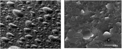
FIGURE 3.9 Examples of tungsten first wall materials damage due to ion implantation. SOURCE: Oak Ridge National Laboratory.
As mentioned earlier, the exposure of the wall surface to MeV and keV ions leads to recoil damage similar to that from neutrons, but it is much more localized. The consequence is sputtering of the surface, which changes its topography as material is removed. Just below the surface, the damage is intense, leading to blistering and exfoliation of wall material. Such effects have been studied; helium production is a major issue. Examples of first wall materials damage due to ion implantation are shown in Figure 3.9.
Although the final stages of the optical elements (mirrors or gratings) for a laser driver may be protected from ion damage by buffer gas and/or magnetic fields, their exposure to X-rays, ions, and energetic neutrons has to be addressed. Some work has been done in this area on fluence limits, but dose rate effects are not yet understood. In addition, where no buffer gas is present the effects from the accumulation of debris from the destruction of the target on the performance of these elements must also be considered.39
Path Forward
Most of the potential problems of the selection of appropriate materials for the walls and final stage optical elements have not yet been addressed at appropriate scale or under the appropriate environmental conditions. With this in mind, it is clear that a major research and development program with large-scale facilities is a necessary part of the development of IFE. It is the committee’s belief that this
__________________________
39 L. Snead, N.M. Ghoniem, and J.D. Sethian, 2001, “Integrated Path for Materials R&D in Laser Inertial Fusion Energy (IFE),” Internal memorandum, Naval Research Laboratory, August.
program is of such a size and complexity that it should be structured very carefully. Its various parts need to be integrated with each particular IFE plant concept, because challenges are often specific to the details. Many materials issues involve understanding the basic science of materials interactions; research in these areas will benefit multiple designs. The timing of the R&D effort has to be matched to the schedule of milestones in the driver, target configuration, and chamber/wall design choices. Those portions that also occur in magnetic confinement fusion, such as neutron damage to structural materials, ion damage to first wall materials and tritium retention concerns, do not have to be duplicated, but one cannot assume that this research will automatically be relevant to both unless the program and facilities are designed with that dual use in mind. The choice of appropriate materials matters and must be considered an integral part of the roadmap to commercial IFE.
Since a decision about the choice of a specific IFE configuration has not yet been made, it is not feasible to suggest a detailed plan for the research and engineering associated with materials that extends in time out to the demonstration plant. A particular IFE configuration brings with it a special set of material-related issues to be addressed; thus, to address all possible materials problems ab initio would be both inefficient and expensive. For example, pulsed-power and heavy-ion fusion are not burdened by the issues of damage to final optical elements that hamper laser drivers. Direct-drive and indirect-drive laser IFE pose different challenges to wall materials, and solid and liquid walls are in themselves substantially different. Initial IFE materials R&D should focus on basic science issues common to multiple designs. The committee offers the following conclusion and recommendations.
Conclusion 3-13: Magnetic fusion energy (MFE) and inertial fusion energy (IFE) share the challenge of 14-MeV neutron damage, which cannot be addressed adequately by fission-reactor-based materials studies. Moreover, owing to the pulsed nature of IFE, there are critical differences between IFE and MFE in the capture and control of X-rays, energetic particles, and neutrons in the surrounding materials and their subsequent damage and response. IFE candidate material solutions will require some different testing and irradiation facilities.
Recommendation 3-5: When a particular IFE option is chosen, a materials R&D program focused on key technical issues should be established immediately and move in parallel with IFE development.
Recommendation 3-6: Since it may be important to identify obstacles in materials properties/performance in order to down-select among the various IFE options, it will be necessary to carry forward a modest materials program. This program should focus on issues that are common to the most
likely IFE choices and, in addition, try to anticipate the serious materials challenges that could affect the choice of an initial IFE prototype.
TRITIUM PRODUCTION, RECOVERY, AND MANAGEMENT
Background and Status
Tritium production, recovery, and management are key to the success of an IFE system. The supply of tritium on Earth is limited (half-life ~12.3 years), so tritium “breeding” is required to ensure a ready supply of fuel for IFE. Tritium self-sufficiency (the “closed” fuel cycle for fusion) is necessary for commercial success or even large-scale test facilities. This requirement brings with it a range of issues, including target performance, tritium breeding potential of the blanket, and the tritium inventory in the IFE system (because tritium is hazardous and readily mobile under certain conditions, there is a trade-off between tritium inventory and safety; see the section Environment, Health, and Safety Considerations, below).
The current section discusses the issues, challenges, and R&D surrounding IFE tritium production, recovery, and management. Several design studies have evaluated tritium-breeding performance and associated tritium inventories.40,41 These studies provide a useful first examination of these issues. The quantitative conclusions from all such studies must be viewed as somewhat uncertain, because they are at a relatively high level and miss many of the issues that become apparent when a system is actually built at engineering scale, revealing, for example, the actual area available for tritium breeding once all the equipment, manifolding, and such are considered).
The tritium inventory in the target fabrication plant is highly dependent on the target performance (lower performance means higher tritium inventory in the targets) and on the process used for target fabrication (see Target Fabrication, above). Depending on the target fabrication process, tritium inventories in the target fabrication plant can be as large as 10 kg. Important in the consideration of tritium inventories is the ability to recover the unused tritium from the unburned DT fuel; as higher burn fraction results in less tritium to recover. In the LIFE concept, estimates suggest that about half of the tritium inventory will be in the target fabrication plant, and total tritium inventory in the LIFE system is <600 g.42 The
__________________________
40 See the studies referenced in the previous section on OSIRIS, SOMBRERO, Prometheus-L and -H, HIBALL, HYLIFE, Z-Pinch, and LIFE.
41 M. Dunne, E.I. Moses, P. Amendt, et al., 2011, Timely delivery of laser inertial fusion energy (LIFE), Fusion Science and Technology 60: 19-27.
42 M. Dunne, R. Al-Ayat, T. Anklam, A. Bayramian, R. Deri, C. Keane, J. Latkowski, R. Miles, W. Meier, E. Moses, J. Post, S. Reyes, V. Roberts, LLNL, 2011, “Answers to the Second Request for Input from the NRC Committee on Prospects for Inertial Confinement Fusion Energy Systems,” LLNL-MI-473693, Response to NAS IFE Committee questions.
SOMBRERO design study claims a similar (300 g) tritium inventory in the target fabrication plant.43
Tritium breeding is accomplished in the blanket. IFE and MFE share tritium breeding needs and basic blanket concepts. The section on reaction chambers above summarizes the types of chambers under consideration for IFE; they fall into two main categories: solid walls and liquid walls. Liquid lithium is an option for liquid walls and has the advantage of relatively high tritium solubility, thus reducing tritium permeation concerns; however, that high solubility can result in undesirably high tritium inventories. Tritium recovery systems have been partially developed and tested at laboratory scale,44 and indicate that acceptable tritium removal and thus inventory limits can be met with these processes; further testing at laboratory and engineering scales is needed to confirm this. Liquid lithium is a superior tritium-breeding medium (compared with molten salt and LiPb) and is therefore attractive from a tritium self-sufficiency point of view.45 Molten salt (e.g., FLiBe) and LiPb have the advantage from a safety point of view of reduced tritium inventories and less chemical activity; however, they have low tritium solubility and thus a higher driving force for permeation (a safety disadvantage) and may require tritium permeation barriers to control the movement of tritium throughout the system.
The SOMBRERO design, shown in Figure 3.10, is considerably different from most other IFE designs: it utilizes a granular Li2O blanket (using gravity to move the particles through the system) that serves as both the coolant and the tritium breeder.46 Low-pressure helium removes the tritium from the Li2O and transports the granules to and from the intermediate heat exchangers. The tritium inventory in the SOMBRERO design was originally estimated at just under 200 g; however, later analysis indicated that the inventory may be 1-2 kg of tritium in the carbon structure,47 emphasizing the potential for uptake of tritium in structural materials (see the section “Materials,” above). A large tritium inventory requires an engineering or materials solution to ensure safety under off-normal conditions (see the section “Environment, Health, and Safety Considerations,” below). Tritium removal from ceramic breeder blankets is also a topic of interest to the
__________________________
43 DOE, 1992, OSIRIS and SOMBRERO Inertial Fusion Power Plant Designs, DOE/ER-54100-1.
44 Ibid.
45 L. El-Guebaly and S. Malang, 2009, Toward the ultimate goal of tritium self-sufficiency: Technical issues and requirements imposed on ARIES advanced fusion power plants, Fusion Engineering and Design 84: 2072-2083.
46 DOE, 1992, OSIRIS and SOMBRERO Inertial Fusion Power Plant Designs, DOE/ER-54100-1.
47 G.L. Kulcinski, R.R. Peterson, L.J. Wittenberg, E.A. Mogahed, and I.N. Sviatoslavsky, 2000, “Dry Wall Chamber Issues for the SOMBRERO Laser Fusion Power Plant,” UWFDM-1126, University of Wisconsin, Madison, June.
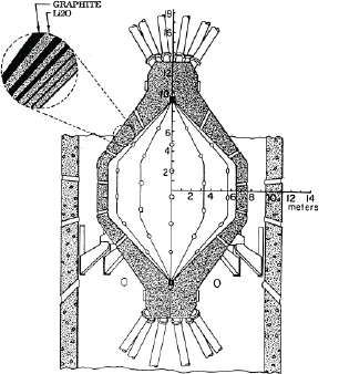
FIGURE 3.10 SOMBRERO’s flowing Li2O granule chamber concept. SOURCE: DOE, 1992, OSIRIS and SOMBRERO Inertial Fusion Power Plant Designs, DOE/ER-54100-1.
ITER test blanket module (TBM) program,48 and the IFE program can leverage those activities.
Each of these studies shows tritium self-sufficiency. However, in actual application, losses due to uptake in structure, process losses, and actual neutron economy will likely be greater than accounted for in the studies. While there are a number of ways to adjust the tritium-breeding ratio (blanket thickness, 6Li/7Li ratio, neutron multiplier), until tritium breeding studies are done for detailed designs, including testing at engineering scale, the tritium self-sufficiency of any design must be considered uncertain. Tritium management will benefit from NIF and OMEGA studies to a limited extent (particularly target fabrication, tritium management,
__________________________
48 H. Albrecht and E. Hutte, 2000, Tritium recovery from an ITER ceramic test blanket module— Process options and critical R&D issues, Fusion Engineering and Design 49-50: 769-773.
tritium handling, and tritium processing). However, the lack of a breeding blanket in NIF leaves an important area in a state of uncertainty.
There has been limited work on liquid and solid breeder blankets in the IFE context. The work in the MFE program could be leveraged. Much could be gained from taking advantage of the larger MFE blanket programs under way in other countries.
Conclusion 3-14: Tritium-breeding performance has been considered in several design studies. These provide a useful initial examination of these issues. As these studies are at a preconceptual design level, they miss many of the issues that become apparent when a system is actually built at engineering scale.
Conclusion 3-15: Tritium recovery systems have been partially developed and tested at laboratory scale, and the signs are that acceptable tritium removal—and thus inventory limits—can be met with these processes. Further testing at laboratory and engineering scale is needed to confirm this.
Conclusion 3-16: Tritium management will benefit from National Ignition Facility (NIF) activities, particularly target fabrication, tritium management, tritium handling, and tritium processing. However, the lack of a breeding blanket in NIF leaves an important area uninvestigated.
Scientific and Engineering Challenges and Future R&D Priorities
The challenges associated with tritium production, recovery, and management are typically engineering and material challenges rather than fusion science challenges. More detailed designs are needed to reduce uncertainties in tritium production calculations. A better understanding of tritium permeation (and methods to reduce permeation) is needed, as is an understanding of tritium uptake in structural materials and tritium removal from breeding blankets.
Path Forward
Near Term (<5 Years)
Needed R&D activities include systems studies; tritium production and recovery studies in liquid and solid blankets (including predictive models); and target studies with a focus on increased burn fraction. Focus in the near term would be on modeling activities.
Medium Term (5-15 Years)
Success would be the validation of tritium production and recovery models in specially designed experiments. Testing of candidate thick liquid (and ceramic granules, if deemed promising in system studies) wall concepts in flow loops, including tritium extraction, and testing of candidate solid walls, including tritium extraction from coolant, would be carried out. Some new facilities would be needed.
Long Term (>15 Years)
The long-term objective would be to develop liquid-wall target chambers operating at 0.1 to 10 Hz or solid wall target chambers to be made available for an FTF and subsequent IFE demonstration plant.
Conclusion 3-18: More detailed designs are necessary to reduce uncertainties in tritium production calculations. A better understanding of tritium permeation (and methods to reduce permeation) is required, together with tritium uptake in structural materials and tritium removal from breeding blankets.
Recommendation 3-7: The work in the magnetic fusion energy program should be leveraged—in particular, the studies for the ITER Test Blanket Module program. Much could be gained from taking advantage of these larger MFE R&D programs under way in other countries.
ENVIRONMENT, HEALTH, AND SAFETY CONSIDERATIONS
Background and Status
Fusion energy has long been seen as having attractive environmental, health, and safety characteristics. The ability to separate the fuel (target) from the chamber system allows selection of structural materials that minimize the production of long-lived isotopes requiring long-term isolation (as is the case for used fuel from a fission reactor). From a safety perspective, tritium is one of the primary safety concerns, as it can be readily mobile under certain conditions. However the overall source term in a fusion system is small compared with the source term in a fission reactor; this should translate into advantages in licensing in the event that fusion approaches commercial deployment. Finally, consideration must be given to the risk of proliferation associated with IFE systems. The committee has had a companion committee, the Panel on the Assessment of Inertial Confinement Fusion Targets, whose charter calls for the consideration of proliferation issues as well
as assessment of target physics, and it has included review of classified materials as needed. The final report of this panel includes its conclusions on proliferation issues related to energy applications of inertial fusion (see Appendix H).
The present section discusses the issues, challenges, and R&D needed to address environment, health, and safety considerations, including plant operation and maintenance, waste streams, and licensing and regulatory considerations.
Plant Operations and Maintenance
Because IFE plants will require a large capital investment, they are most suited for baseload operations. This will require minimal downtime, an attribute that has been attained by commercial fission plants in the United States (demonstrating over 90 percent availability on average), but only after many years of operational experience. The fission industry has developed a tightly coordinated set of maintenance activities that are timed to coincide with fueling outages; IFE plants should be able to develop a similar set of coordinated maintenance activities, but it will take some years of operational experience to do so.
Several design studies have included a discussion of maintenance.49 Avoiding frequent replacement of components that are difficult to access and replace will be important to achieving high availability. Such components will need to achieve a very high level of operational reliability. Technology challenges discussed in this chapter must be overcome to maximize availability, and operating experience in prototypical environments is needed.
An important contributor to good availability is hands-on maintenance wherever possible.50 Hands-on maintenance is typically faster than remote maintenance and may be less expensive.51 Activation products in coolant streams should
__________________________
49 See, for example, M. Dunne, R. Al-Ayat, T. Anklam, A. Bayramian, R. Deri, C. Keane, J. Latkowski, R. Miles, W. Meier, E. Moses, J. Post, S. Reyes, and V. Roberts, LLNL, 2011, “Answers to the Second Request for Input from the NRC Committee on Prospects for Inertial Confinement Fusion Energy Systems,” LLNL-MI-473693, Response to NAS IFE Committee questions; DOE, 1992, OSIRIS and SOMBRERO Inertial Fusion Power Plant Designs, DOE/ER-54100-1; DOE, 1992, Inertial Fusion Energy Reactor Design Studies Prometheus-L and Prometheus-H, DOE/ER-54101; B. Badger, K. Beckert, R. Bock, et al., 1981, HIBALL—A Conceptual Heavy Ion Beam Fusion Reactor Study, UWFDM-450, University of Wisconsin at Madison, and KFK-3202, Kernforschungszentrum Karlsruhe; J.A. Blink, W.J. Hogan, J. Hovingh, W.R. Meier, and J.H. Pitts, 1985, The High Yield Lithium Injection Fusion Energy (HYLIFE) Reactor, UCRL-53559, LLNL.
50 M. Dunne, R. Al-Ayat, T. Anklam, A. Bayramian, R. Deri, C. Keane, J. Latkowski, R. Miles, W. Meier, E. Moses, J. Post, S. Reyes, V. Roberts, LLNL, 2011, “Answers to the Second Request for Input from the NRC Committee on Prospects for Inertial Confinement Fusion Energy Systems,” LLNL-MI-473693, Response to NAS IFE Committee questions.
51 S.J. Piet, S.J. Brereton, J.M. Perlado, Y. Seki, S. Tanaka, and M.T. Tobin, 1996, “Overview of Safety and Environmental Issues for Inertial Fusion Energy,” INEL-96/00285.
be minimized to avoid exposure of plant personnel and maximize hands-on maintenance. Because fusion plants use tritium for fuel, maintenance activities must be done with attention to its presence (it can be very mobile; see the tritium management section above). Some designs utilize modular components for ease of maintenance and replacement.52 Remote maintenance will be needed for some components and areas of the power plant. The IFE program should learn from remote maintenance activities at ITER and NIF and from the extensive long-term program on the Joint European Torus (JET).53
Because there are at present no important IFE test facilities that include a significant technology mission, there is no opportunity to test in IFE-prototypic conditions. As was discussed earlier in this section, achieving high levels of component reliability requires substantial testing and qualification of fusion components, far beyond what is available today.
The environment, health, and safety issues associated with plant operations and maintenance of an IFE power plant are expected to be substantially similar to those of current fission nuclear power plants. While fusion reactors will not have to deal with nuclear fuels and their resulting fission products, high levels of radiation and large amounts of radioactive materials will have to be safely handled. These will come from activation of the structural materials of the reactor and activated corrosion products in the coolant streams, as well as the presence of tritium. Fusion reactors will have to deal with significantly larger quantities of tritium than do fission reactors, as is discussed in the section “Tritium Production, Recovery, and Management,” above.
Waste Streams
The IFE design studies that have been done over the years typically quantify the waste streams associated with each design.54 The U.S. Nuclear Regulatory
__________________________
52 M. Dunne, R. Al-Ayat, T. Anklam, A. Bayramian, R. Deri, C. Keane, J. Latkowski, R. Miles, W. Meier, E. Moses, J. Post, S. Reyes, V. Roberts, LLNL, 2011, “Answers to the Second Request for Input from the NRC Committee on Prospects for Inertial Confinement Fusion Energy Systems,” LLNL-MI-473693, Response to NAS IFE Committee questions.
53 See http://tinyurl.com/c78oqfz for more information.
54 DOE, 1992, OSIRIS and SOMBRERO Inertial Fusion Power Plant Designs, DOE/ER-54100-1; DOE, 1992, Inertial Fusion Energy Reactor Design Studies Prometheus-L and Prometheus-H, DOE/ER-54101; B. Badger, K. Beckert, R. Bock, et al., 1981, HIBALL—A Conceptual Heavy Ion Beam Fusion Reactor Study, UWFDM-450, University of Wisconsin at Madison, and KFK-3202, Kernforschungszentrum Karlsruhe; J.A. Blink, W.J. Hogan, J. Hovingh, W.R. Meier, and J.H. Pitts, 1985, The High Yield Lithium Injection Fusion Energy (HYLIFE) Reactor, UCRL-53559, LLNL; C.L. Olson, 2005, “Z-Pinch Inertial Fusion Energy,” Landolt-Boernstein Handbook on Energy Technologies, Volume VIII/3, Springer-Verlag, Berlin; J.D. Sethian, D.G. Colombant, J.L. Giuliani, et al., 2010, The science and technologies for fusion energy with lasers and direct-drive targets, IEEE Transactions on Plasma Science 38(4): 690-703; M. Dunne, E.I. Moses, P. Amendt, et al., 2011, Timely delivery of laser inertial fusion energy (LIFE), Fusion Science and Technology 60: 19-27; J.F. Latkowski, R.P. Abbott, S. Aceves, et al., 2011, Chamber design for the laser inertial fusion energy (LIFE) engine, Fusion Science and Technology 60:54-60; L. Cadwallader, L. and L.A. El Guebaly, 2011, Safety and environmental features, Nuclear Energy Encyclopedia: Science, Technology, and Applications, p. 413, Wiley & Sons; L.A. El-Guebaly, P. Wilson, and D. Paige,2006. Evolution of clearance standards and implications for radwaste management of fusion power plants, Fusion Science and Technology 49: 62-73.
Commission (US NRC) governs disposal of radioactive waste in the United States; the regulations are covered in the U.S. Code of Federal Regulations, 10CFR61.55 IFE and MFE designs have focused on the use of “low activation materials” that minimize the production of isotopes with long half-lives, with a goal of eliminating—or reducing as much as possible—waste that requires geologic disposal (of course the material must still function in its intended role, and this provides many challenges; see the section on materials issues above). Near-surface disposal (as opposed to geologic disposal) depends on specific activity limits (SALs), which are based on the direct gamma exposure from gamma-emitting radionuclides and the inhalation and ingestion of beta-emitting radionuclides. The radionuclides in 10CFR61 are for fission-based isotopes, but applying the same methodology produces SALs for fusion-based isotopes.56
Fusion design studies have included a focus on minimizing the production of waste requiring geologic disposal. This has been done through careful choice of materials—for example, by limiting Nb and Mo impurities in structural material,57 by using SiC-based, low-activation materials,58 or by possibly filtering out some radioactive elements from liquid wall materials. These actions typically increase the cost of the plant but reduce the cost of disposal into a mined geologic repository such as WIPP or the stalled Yucca Mountain. Also, recycling target material is helpful for minimizing waste.
The fusion community has been successful in designing power plants that meet the goal of reducing or even eliminating the production of high-level waste. However, the amount of low-level waste that requires disposal, albeit near-surface, is likely to be very large.59 Figure 3.11 shows a comparison of waste volume for magnetic fusion
__________________________
55 Code of Federal Regulations, Title 10: Energy, Part 61—Licensing Requirements for Land Disposal of Radioactive Waste (Nuclear Regulatory Commission), Office of the Federal Register, National Archives and Records Administration, Revised as of January 1, 1991.
56 E.T. Cheng, 2000, Waste management aspect of low activation materials, Fusion Engineering and Design 48: 455-465.
57 L.A. El-Guebaly and the ARIES Team, 2000, “Views on Neutronics and Activation Issues Facing Liquid-Protected IFE Chambers, Topical on Fusion Energy,” 14th ANS Topical Meeting on Fusion Energy, Park City, Utah, October.
58 L.A. El-Guebaly, P. Wilson, D. Henderson, L. Waganer, and R. Raffray, 2003, Radiological issues for thin liquid walls of ARIES IFE study, Fusion Science and Technology 44: 405-409.
59 S. Reyes, J. Sanz, J. Latkowski, 2002, Use of Clearance Indexes to Assess Waste Disposal Issues for the HYLIFE-II Inertial Fusion Energy Power Plant Design, UCRL-JC-147039, LLNL, January 17, 2002.
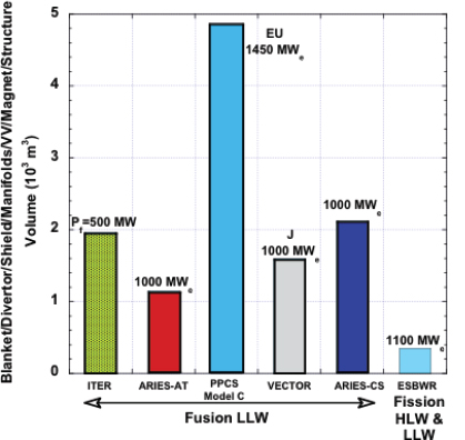
FIGURE 3.11 Lifetime radioactive waste volume comparison for various MFE designs (actual volumes of components; not compacted, no replacements; bioshield excluded). LLW, low-level waste; HLW, high-level waste. SOURCE: L. El-Guebaly et al., 2008, Goals, challenges, and successes of managing fusion activated materials, Fusion Engineering and Design 83: 928-935.
designs;60 inertial fusion designs have similar volumes.61 Low-level waste disposal facilities in the United States are becoming oversubscribed, and siting a new low-level waste disposal facility is also likely to be a very difficult. There have been some studies looking at the potential for recycling radioactive materials to reduce the amount
__________________________
60 L. El-Guebaly, V. Massaut, K. Tobita, L. Cadwallader, 2008, Goals, challenges, and successes of managing fusion activated materials, Fusion Engineering and Design 83: 928-935.
61 S. Reyes, J. Sanz, J. Latkowski, 2002, Use of Clearance Indexes to Assess Waste Disposal Issues for the HYLIFE-II Inertial Fusion Energy Power Plant Design, UCRL-JC-147039, LLNL, January 17, 2002.
of material that must be stored.62 Further analysis will be needed to determine the practicality and net cost of this approach. Recycling and reuse of materials within the fusion system—as opposed to “free release” of recycled material—is likely to meet with less resistance from regulators, the recycling industry, and the public.63
Of particular importance are those waste streams that are considered “mixed waste.” Mixed waste has both a chemical hazard and a radiation hazard; irradiated lead is an example of a mixed waste. Lead is a coolant candidate as well as a target material candidate. Mixed waste currently has no disposition path in the United States, but regulations governing its disposal are under development and would likely be in place before deployment of the first commercial fusion plant.
Conclusion 3-19: Design studies of inertial fusion energy power plants indicate that, with the use of low-activation materials, it will be possible to minimize high-level waste. However, the amount of waste that requires disposal, albeit near the surface, may be very large. Low-level waste disposal in the United States is becoming increasingly difficult.
Recommendation 3-8: There have been studies that examine the potential for recycling and reuse of radioactive materials within the fusion system to reduce the amount of material that must be disposed of; the committee encourages the continuation of these studies.
Licensing and Regulatory Considerations
The United States Nuclear Regulatory Commission (NRC) is a conservative body. This is appropriate given its role in the oversight of U.S. commercial nuclear facilities. The vast majority of the NRC’s licensing experience has been with light water reactors (LWRs), and its regulations, for the most part, have grown out of the LWR experience. Licensing a fusion power plant will require blazing new trails, and it will be important for the fusion community to work with the NRC to help it to understand the hazards (which are much different from the hazards in an LWR) and their mitigation in a fusion power plant. Communication early in the process is important to a successful outcome.64
__________________________
62 L. El-Guebaly, R. Pampin, M. Zucchetti, 2007, Clearance considerations for slightly-irradiated components of fusion power plants, Nuclear Fusion 47(7): S480-S484; L. El-Guebaly, M. Zucchetti, L.D. Pace, B.N. Kolbasov, V. Massaut, R. Pampin, et al., 2009, An integrated approach to the back-end of the fusion materials cycle, Fusion Science and Technology 52(2): 109-139.
63 National Research Council, 2002, The Disposition Dilemma: Controlling the Release of Solid Materials from Nuclear Regulatory Commission-licensed Facilities, National Academy Press, Washington, D.C.
64 R.A. Meserve, Carnegie Institution for Science, “Licensing a Commercial Inertial Confinement Fusion Energy Facility,” Presentation to the Committee on October 31, 2011.
Some licensing and regulatory-related work has been done for the ITER program, and much of that work provides insights into IFE licensing processes and issues. The LIFE program has considered licensing issues more than any other IFE program; however, much more effort would be needed if IFE were to seriously pursue an NRC license. The Next Generation Nuclear Plant (NGNP) fission reactor project plans to license and build a high-temperature gas fission reactor. Gas reactors have been built and operated previously in the United States and Europe, although at lower operating temperatures than are envisioned for the NGNP. The licensing strategy developed for the NGNP provides a good picture of the challenges associated with licensing a relatively standard technology.65
The licensing of fission power plants is moving toward a risk-informed approach, whereas in the past it took primarily a deterministic approach. The LIFE program is developing a similar approach.66 The favorable safety characteristics of the IFE and MFE fusion plants should simplify the licensing process; however, the burden of proof for IFE plants will be no different than for fission plants. One of the safety-related goals for fusion is to demonstrate that there would never be a need for public evacuation under any event. This is a clear example of the favorable safety characteristics of a fusion plant.
Conclusion 3-20: Some licensing/regulatory-related research has been carried out for the ITER (magnetic fusion energy) program, and much of that work provides insights into the licensing process and issues for inertial fusion energy. The laser inertial fusion energy (LIFE) program at Lawrence Livermore National Laboratory has considered licensing issues more than any other IFE approach; however, much more effort would be required when a Nuclear Regulatory Commission license is pursued for inertial fusion energy.
Safety analysis has been an important part of the IFE design studies cited earlier. Early analyses were relatively simple. They often looked at total inventories of radioactive material and determining how much material could be released based on total system energy. These analyses have given way to more sophisticated analyses, sometimes employing tools originally developed for the fission industry and adapted to fusion.67 Tritium inventory and release mitigation is an important part of the fusion safety case. Tritium can be highly mobile under certain condi-
__________________________
65 Next Generation Nuclear Plant Licensing Strategy—A Report to Congress, www.ne.doe.gov/pdfFiles/NGNP_reporttoCongress.pdf, August 2008.
66 M. Dunne, E.I. Moses, P. Amendt, et al., 2011, Timely delivery of laser inertial fusion energy (LIFE), Fusion Science and Technology 60: 19-27.
67 B.J. Merrill, A lithium-air reaction model for the MELCOR code for analyzing lithium fires in fusion reactors, Fusion Engineering and Design 54: 485-493.
tions, so minimizing its inventory in fusion facilities is a first step (see the section on tritium management above). Other radioactive material present in the IFE plant must also be considered, together with possible release scenarios. Overall, the IFE source term is significantly smaller than its fission counterpart, which should benefit the licensing process. Analysis done for systems studies shows acceptable safety performance; however, in the absence of experimental results to validate models, the actual performance remains highly uncertain. Validation and verification of models is extremely important to the NRC and will be an important factor in the licensing process.
Recommendation 3-9: Validation and verification of models is extremely important to the Nuclear Regulatory Commission and will be an important factor in the licensing process. Development of models, including validation and verification, should be pursued early. Working with the NRC early and often will be important, as well as looking to other programs (e.g., ITER and fission) for successful licensing strategies.
Scientific and Engineering Challenges and Future R&D Objectives
The environmental, safety, and health aspects of the IFE facilities should continue to be an important point of discussion in any program. The IFE community should continue to analyze and bring attention to the favorable characteristics of these plants. Continued development of sophisticated models, together with data for validation of the models, is important in the preparation for licensing of an IFE plant. The IFE program should continue to keep abreast of NRC licensing activities and keep the lines of communication with the NRC open.
Path Forward
Near Term (<5 Years)
Needed R&D activities include systems studies with a focus on realistic assumptions and schedules. Radioactive waste management should be an area of particular focus given recent activities by the Blue Ribbon Commission on America’s Nuclear Future (BRC).68 The development of a safety model, with an eye towards future licensing, and the development of experiments to validate models will be critical.
__________________________
68 The BRC was created under the authority of DOE and tasked with devising a new strategy for managing the back end of the nation’s inventory of nuclear fuel cyclewaste; it issued its final report in January 2012. A copy of the report and other information on the commission can be obtained at http://tinyurl.com/bvsshko; accessed on May 16, 2013.
Medium Term (5-15 Years)
Concepts for recycling IFE target and chamber materials need to be studied experimentally, possibly using only nonradioactive elements. Experiments would be done to benchmark accident analysis codes with materials and configurations typical of fusion power plant designs. Success would be experimental validation of safety models.
Long Term (>15 Years)
The long-term objective would be to begin development of the licensing case for an IFE demonstration plant.
BALANCE-OF-PLANT CONSIDERATIONS
The purpose of an IFE power plant is to produce useful energy in the form of electricity or high-temperature process heat, or chemical energy in the form of hydrogen. To do this, the power plant must convert the energetic products of fusion reactions—high-energy neutrons and charged particles—into the desired useful forms. To become a practical source of energy, IFE must produce and convert the fusion energy in a manner that is technically feasible, environmentally acceptable, and economically attractive compared to other long-term, sustainable sources of energy.
The high-energy neutrons and charged particles from the fusion reactions deposit their thermal energy on the walls of the reaction chamber and in the tritium-breeding blanket surrounding the chamber. Everything outside the chamber and blanket, excluding the laser or particle beam drivers or the pulsed power system, is considered the “balance of plant” (BOP). The BOP includes the systems for conversion of thermal energy to electricity, the buildings and structures for the power plant, and all the conventional services. While schemes have been proposed to convert some of the charged-particle energy directly into electricity by electrostatic or magnetohydrodynamic processes, first-generation IFE power plants will most likely utilize fairly conventional thermal power conversion systems to convert the energy contained in the hot coolant from the chamber wall and blanket into electricity. Similar “heat engine” thermal power conversion systems are widely used on nuclear fission power plants and on fossil-fired power plants around the world. The Rankine cycle, or steam cycle, and the Brayton cycle, or gas-turbine cycle, are widely used heat engines that appear well suited for application to the conversion of thermal energy from fusion into electricity. There appears to be little need for power conversion system development that would be unique to fusion or IFE, although IFE-specific BOP designs will need to be developed, and opportunities for innovation should always be welcome.
Conclusion 3-21: Existing balance-of-plant technologies should be suitable for IFE power plants.
The thermal conditions—inlet and outlet coolant temperatures—proposed for IFE power plants are similar to those used by fission and fossil power plants today, so that the BOP for an IFE power plant should likewise be very similar to those used today. An area of concern is that of system interfaces and the possibility of hazardous material transport across those interfaces. The IFE reaction chamber will contain quantities of radioactive tritium, radioactive target debris, and some radioactive material sputtered from the first wall. In addition, it will operate at elevated temperatures. Tritium may migrate through the chamber walls and into the primary coolant stream. The coolant will pass through heat exchangers, and tritium may migrate through the heat exchangers into the secondary coolant and eventually into the rest of the power plant and even into the environment. These issues are part of the larger tritium control issue discussed in the section on tritium management, above. These interface concerns may require R&D to develop coatings for BOP components and heat exchangers that are resistant to permeation by tritium and tritium removal systems for the various chamber, blanket, and power conversion system coolants.
Path Forward
Near Term (<5 Years)
The design and analysis of BOP systems will continue to be included in IFE system studies and design studies, with emphasis on identification and evaluation of critical issues.
Medium Term (5-15 Years)
As favored design concepts begin to emerge, R&D into critical issues that have been identified—such as tritium permeation and control—will need to be carried out.
Long Term (>15 Years)
BOP systems will need to be developed and deployed as part of demonstration IFE systems.
An essential requirement for any new energy system to compete in future markets is to offer a product at a competitive price. For an IFE power plant, the main measure is the cost of electricity (COE). The formula for the COE is typically given by:
COE = (Ccap × FCR + Cfuel + COM)/(Penet × 8,760 (hr) × Fcap) + Decom
where Ccap, construction costs including interest charges during construction; FCR, fixed charge rate; Cfuel, fuel costs including targets; COM, operations and maintenance; Penet, net electric power; Fcap, capacity factor; and Decom, annual decommissioning charge in mills per kilowatt-hour or $/MWh, which can be calculated as the cost of decommissioning, times the appropriate annual sinking fund factor to accumulate those funds, divided by the amount of electricity produced per year (Penet × 8,760 (hr) × Fcap).
Conclusion 3-22: An essential requirement for any new energy system to compete in future markets is to offer a product at a competitive price. For an IFE power plant, the main measures are the cost of electricity generation and, in particular, the capital cost.
The capacity (or sometimes called the availability) factor (Fcap) has a large influence on the COE. It is the crucial number in converting capital costs to COE. IFE power systems will be very capital-intensive systems with perhaps relatively modest fuel costs, provided the goals of low-cost targets can be met (discussed further below). Such plants will likely operate as base-load power plants where a premium is placed on operating at the maximum capacity factor. IFE power plant studies typically assign a value of 70 percent to 80 percent to Fcap. These values cannot be achieved today given the early stages of IFE technology development, so really they represent a goal. By way of comparison, the current fleet of fission power plants in the United States routinely achieves an average capacity factor of about 90 percent.
Achieving high capacity factors requires two basic features of the system: high component reliability (usually measured by the mean-time-to-failure for each component) and acceptable maintenance or downtimes (usually measured by the mean-time-to-repair for each component). There is a strong relationship between the allowed values of the mean-time-to-failure and the mean-time-to-repair for a given component. The longer mean-time-to-repair, the longer must be the mean-time-to-failure. In other words, the harder it will be to replace the component, the higher must be the degree of reliability. Defining the acceptable values for the
mean-time-to-failure and mean-time-to-repair for all the components in a complex IFE power plant will require a comprehensive systems engineering approach.
Achieving high levels of component reliability requires substantial testing and qualification of fusion components, far beyond what is available today. For example, no fusion reaction chamber has ever been built and certainly none has been tested to the extent needed to establish failure modes and a reliability database. Given the large number of components and systems in an IFE power plant (and an MFE power plant), a substantial investment of time and money will be required to conduct those tests and they will have an enormous impact on the overall time horizon for developing commercial IFE systems. Although much useful testing can and will be done in simulation facilities, at some time, testing in an actual fusion environment will be needed. These very large investments with long timescales will thus have a profound impact on the roadmap for realizing fusion power systems. While ITER and a future IFE demonstration plant are very different, it should be possible to take advantage of some of the experience with ITER—for example, the hardware and procedures developed for remote maintenance—to reduce the implementation time for an IFE demonstration plant.
Achieving high capacity factors (availability) in light of an IFE system’s components is an equally challenging task. Some of these components will necessitate using remote handling systems. While the technology and experience in other fields (e.g., fission reactors and space systems) can be adapted to fusion needs, there exists today very limited experience with remote maintenance in fusion systems. ITER is one very important source of such information. Developing the maintenance systems for an IFE power plant will entail a significant effort, but there is very little work under way today in the United States to support those efforts.
For these reasons, the capacity factor is probably the most unpredictable of all the factors that affect the COE. This is true of both fusion concepts, inertial and magnetic.
Conclusion 3-23: As presently understood, an inertial fusion energy power plant would have a high capital cost and would therefore have to operate with a high availability. Achieving high availabilities is a major challenge for fusion energy systems. It would involve substantial testing of IFE plant components and the development of sophisticated remote maintenance approaches.
Of special concern for the economics of IFE is the cost of the targets. The feasibility of developing successful fabrication and injection methodologies at the low cost required for energy production—about $0.25 to $0.30/target,69 or about
__________________________
69 W.S. Rickman and D.T. Goodin, 2003, Cost modeling for fabrication of direct drive inertial fusion energy targets, Fusion Science and Technology 43(3): 353-358.
one ten thousandth of current costs, and at a production rate that is 100,000 times faster than current rates—is a critical issue for inertial fusion. IFE researchers working on target capsule costs argue that between increased yields and batch-size increases, cost reductions of two orders of magnitude are possible with significant development programs.70 It appears that the target-cost numbers may be possible, although challenging, considering the number of assumptions and judgments that are needed to get to the desired reduction of a factor of 10,000.
Conclusion 3-24: The cost of targets has a major impact on the economics of inertial fusion energy power plants. Very large extrapolations are required from the current state-of-the-art for fabricating targets for inertial confinement fusion research to the ability to mass-produce inexpensive targets for inertial fusion energy systems.
Construction or capital costs are typically divided into fusion-specific components (e.g., laser or particle-beam drivers, chambers, and target fabrication and injection) and the BOP. The BOP was discussed in the preceding section and will likely rely on existing concepts with cost estimates that are relatively well known. Cost estimates for the fusion components necessarily entail more uncertainty because in some instances (e.g., chambers and high-capacity target fabrication) they are still in the very early stages of development. Nevertheless, the construction costs have less uncertainty than the capacity factor.
In fission electricity experience, standard project costs (e.g., owner’s cost and engineering during construction) are typically taken as a percentage of the basic capital cost. Escalation and inflation factors may also be incorporated.
The IFE COE estimated in various studies falls between 5 and 10 cents/kWh in current dollars.71 These estimated COEs for IFE power plants are in the same general range as COEs for other energy options, but because of the relatively early phase of the development of IFE components and systems, much uncertainty surrounds them. It appears that the COE numbers obtained in past studies are pos-
__________________________
70 D.T. Goodin, N.B. Alexander, L.C. Brown, D.T. Frey, R. Gallix, C.R. Gibson, et al., 2004, A cost-effective target supply for inertial fusion energy, Nuclear Fusion 44(12): S254-265.
71 DOE, 1992, OSIRIS and SOMBRERO Inertial Fusion Power Plant Designs, DOE/ER-54100-1, Volume 1. Executive Summary and Overview; T. Anklam, LLNL, “Life Delivery Plan,” Presentation to committee on March 30, 2011; B. Badger, D. Bruggink, P. Cousseau, et al., 1995, LIBRA-SP, A Light Ion Fusion Power Reactor Design Study Utilizing a Self-Pinched Mode of Ion Propagation—Report for the period ending June 30, UWFDM-982 University of Wisconsin Fusion Technology Institute; J.T. Cook, G.E.Rochau, B.B. Cipiti, C.W. Morrow, S.B. Rodriguez, C.O. Farnum, et al., 2006, Z-Inertial Fusion Energy: Power Plant, SAND2006-7148, SNL; M. Dunne, LLNL, “Overview of the LIFE Power Plant,” Presentation to the committee on January 29, 2011; I.N. Sviatoslavsky, et al., 1993, “SIRIUS-P, An Inertially Confined Direct Drive Laser Fusion Power Reactor,” UWFDM-950, University of Wisconsin Fusion Technology Institute.
sible, but they contain uncertain components owing to the untested assumptions that must be made when making estimates for new technology.
Financing and business considerations, such as the fixed charge rate (capital charge rate), will have an important influence on the COE. Usually this is made up of two parts: a charge rate for the share held by equity investors and a (lower) charge rate for the debt-investor share. These terms can vary based on the confidence investors have in the readiness and cost-effectiveness of the technology and the extent to which the investment is protected. Investment can be protected in some states by a decision of the public utility commission. Debt investment can be protected by federal loan guarantees or by direct federal assumption of the debt. The charge rate for IFE will be determined by the entire history of the technology. The more complex the technology, the more prone it is to delays and bumps along the road to implementation and the bigger the effect on investor and guarantor psychology.
For example, most past IFE cost of electricity studies did not carry individual uncertainty ranges. Some of the difficulties in using estimates of electricity costs for IFE in comparison with other energy technologies or among IFE options could be overcome, in part, if uncertainty ranges were a required component of cost estimates.
It is not clear to what extent the COE studies for IFE are “forward” estimates (made without looking at a cost goal) or “backward” estimates (made with an eye on a cost goal), or a mixture of the two. Certainly, the BOP estimates can be based on conventional databases of cost elements and would qualify as forward cost estimates. They can be compared to cost estimates made for other, traditional energy technologies, with the caveat that future estimates for all technologies may be low when compared to actual as-built and as-operated facilities. Hence, cost estimates for fusion, even were they to be based totally on forward calculations, should be compared to estimates of future COEs for other technologies, not current-day market prices.
Cost estimates for the purely fusion components of the COE may have been, to some degree, backward estimates, starting from values based on views of future prices of the alternatives. Analysts taking this approach would determine if it was possible to reach such targets for the fusion components of the COE and then use those possible numbers to compute a total COE. In such cases, the fusion COEs might be better labeled “possible values” rather than COE estimates.
In addition to predicting possible COE values, cost analysis can help to identify where R&D dollars should be targeted. The sensitivity of total cost-to-cost variations in system components helps to identify where a reduction in cost (via R&D, for example) would have the greatest impact. The effectiveness of such analyses depends critically on having a well-developed system engineering capability.
Similarly, the technology readiness level (TRL) process is another useful tool
that is also discussed in Chapter 4.72 In dealing with uncertainty ranges, the use of TRLs for each component, with separate uncertainty ranges on the component COE appropriate for different TRLs, could help planners decide on where in order to allocate resources to lower costs. Such a methodology would help to standardize cost and uncertainty estimates across different fusion technologies; it is discussed further in Chapter 4.
Use of TRLs and other readiness concepts, such as “integration readiness levels,”73 also provide structure for keeping costs under control. There have been problems historically with cost escalation in government/industry partnerships from which useful lessons for IFE can be drawn. For instance, many large DOE programs/projects did not proceed as planned. Although there are many reasons why projects may fail technically or not meet their cost objectives, two stand out and are worth special consideration given the charge to this committee: (1) the breakdown of large, multiowner projects, and (2) significant cost increases in large, first-of-a-kind demonstration or prototype plants. The committee believes that the TRL methodology should be required for all major components of the IFE program.
It is important to note that the COE for IFE may not be the most immediate obstacle to successful development. At the size currently envisioned in most studies, the total cost of an IFE plant may be the biggest obstacle to IFE development, when looked at through the prism of current-day electricity company concerns. Given the rapid escalation in capital costs over the last decade, projected costs of gigawatt facilities for all capital-intensive electricity plants have reached the point where they represent a significant fraction of company capitalizations, making investments a “bet-the-company” decision. Efforts are under way to downsize electricity plants to reduce the sticker shock. A national IFE program should explore a range of plant sizes given the uncertain market and financial situation in this country in the coming decades. In particular, it is very important to understand the lower bound for an IFE plant output in terms of key physics constraints (e.g., target energy gain) and engineering constraints.
Conclusion 3-25: The financing of large, capital-intensive energy options such as an IFE power plant will be a major challenge.
R&D can attempt to address the two major economic obstacles confronting IFE—namely, skepticism about reaching cost/kWh targets and the high cost per
__________________________
72 DOE, 2011, Technology Readiness Assessment Guide, DOE G 413.3-4A, Washington D.C.: Department of Energy.
73 See J.C. Mankins, 2002, Approaches to strategic research and technology (R&T) analysis and road mapping, Acta Astronautica 51(1-9): 3-21 and B. Sauser, J.E. Ramirez-Marquez, R. Magnaye, and W. Tan, 2008, A systems approach to expanding the technology readiness level within defense acquisition, International Journal of Defense Acquisition Management 1: 39-58.
plant. R&D can also attempt to reduce investor risk, whether for government or private investors, by encouraging innovation in IFE components and designs, improving TRLs through engineering advances, and by laying the ground for spin-offs of private companies.
Systems analysis—in this context, the purely technical quantitative assessment of the expected performance of various interconnected technologies—is an important tool in the development of any complex system.74 Systems analysis can also identify outcomes of various implementation scenarios based on various assumptions. It is primarily concerned with the performance of various technologies and does not address the pathways or nontechnical constraints in achieving the implementation of those technologies. However, it does enable assessing the sensitivity of the system to nontechnical constraints translated into system impacts. Cost assessment is one of the outcomes of a systems analysis, as discussed earlier.
As already mentioned, the cost of a plant generating 1 GW or more of electricity represents a considerable portion of the book value of any U.S. company likely to build a fusion reactor: this is in and of itself a huge barrier to entry. There is another problem specific to those high-capitalization facilities that might be built in the many states in the United States in which competitive, short-term electricity markets have been established. A fusion facility, like a nuclear fission facility, will not pay off its investors for a long time. In the absence of long-term contracts, these facilities would endure an extended period of vulnerability to market prices dropping, forcing bankruptcy and massive losses. While it could be that long-term contracts will be established in such markets in the years ahead, until that time, investments in expensive, capital-intensive projects are risky in competitive markets. Investors would therefore be looking for a high rate of return, driving up the per-kilowatt-hour cost.
The fission industry is working to modularize and downsize electricity plants to reduce the high costs and impact on the grid. Fusion R&D might want to follow that example. One goal of R&D could be to design IFE power plants that are naturally smaller or radically cheaper or to improve existing designs. Designers might explore modular systems in which relatively small fusion devices—built in sequence as finances allow—share common driver facilities. The assignment of an “investor readiness level” to a design, including differentiated levels of readiness to venture capitalists, equity investors, and debt investors, could prove a useful discipline for planning. Even though the COE might be higher, a smaller plant might be more viable in the United States because its total cost is more attractive to potential investors.
__________________________
74 K.A. McCarthy and K.O. Pasamehmetoglu, “Using Systems Analysis to Guide Fuel Cycle Development” (Paper 9477, INL/CON-09-15764). In: Global 2009, Paris, 2009.
Because it is not possible to anticipate which business model will be the most successful decades from now, a long-range technology should have an eye on supporting multiple business models. These models range from those in which the U.S. government stands behind the technology, maintains a high percentage of the ownership of the construction, and even operates the plant, to a model in which venture capitalists support small companies and obtain key patents on IFE components, to a model where the government builds a few facilities with the idea that private companies will step in afterward to improve and market the by then proven technology.
Government support for R&D, as part of or in addition to systematic engineering approaches, could greatly benefit IFE under all of these business models. Rewarding innovation as part of engineering could provide a stronger base from which spinoff companies could arise. Encouraging ideas from a larger community than is now involved in IFE efforts could contribute to increased innovation and could also increase the number of patents likely to be developed, which is a prerequisite for the venture capital model.
Based on the information in this section and its conclusions, the committee makes three recommendations:
Recommendation 3-10: Economic analyses of inertial fusion energy power systems should be an integral part of national program planning efforts, particularly as more cost data become available.
Recommendation 3-11: A comprehensive systems engineering approach should be used to assess the performance of IFE systems. Such analysis should also include the use of a technology readiness levels (TRLs) methodology to help guide the allocation of R&D funds.
Recommendation 3-12: Further efforts are needed to explore how best to minimize the capital cost of IFE power plants even if this means some increase in the cost of electricity. Innovation will be a critical aspect of this effort. Possible options include use of a smaller fusion module, even at higher specific capital cost per megawatt of electricity, and the use of a fusion module for which capital cost is reduced by accepting a higher operating cost.


