
Appendix D
Test Range Description and the Ballistic Testing Process
The combat helmet test range at Aberdeen Test Center (ATC) is shown in Figures D-1a and D-1b. The ATC firing range uses a rifle-like test barrel to fire a projectile against a helmet. Electronic instrumentation is used to measure projectile velocity before impact. Tested helmets are affixed to headforms that are packed with modeling clay, where the clay serves as a recording medium.
Per the Director of Operational Test and Evaluation (DOT&E) test protocol, the test range is set up in accordance with a variety of ATC Test Operating Procedures; see Table 1 in the DOT&E FAT and LAT protocols (DOT&E, 2010, 2012). The test ranges are environmentally controlled at 68 ±10°F and a relative humidity of 50 ±20 percent (ATC, 2013).
Per ATC (2013), in the range set-up, the test barrels are mounted in a universal receiver, and the weapon is fired using a solenoid. A double base configuration of light screens is used to measure projectile velocity, and drag is applied to calculate strike velocity. A yaw card is used in conjunction with a go/no-go gauge to check the striking yaw of the projectile.
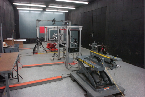
FIGURE D-1a The helmet test range at the U.S. Army Aberdeen Test Center. SOURCE: Kyle Markwardt, Test Officer, Aberdeen Test Center, “Helmet IOP PED-003 Briefing to NRC Helmet Protocols Committee,” presentation to the committee on March 22, 2013.
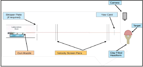
FIGURE D-1b Typical test range at set-up for helmet V0 testing. SOURCE: ATC (2012).
In general, the test is conducted in accordance with National Institute of Justice (NIJ) Standard 0106.01 with the following four exceptions (NRC, 2012):
• Test items may be conditioned as required.
• Test distances may be altered.
• The ATC headform is modified from the NIJ head-form with slots in both the coronal and midsagittal directions.
• Striking velocities are calculated according to the U.S. Army Test and Evaluation Command International Test Operating Procedure 4-2-805 in order to determine if a shot is fair (DOT&E, 2010).
Ballistic testing of combat helmets involves both the evaluation of resistance to penetration (RTP) and helmet backface deformation (BFD) as recorded in clay. With the exception of V50 testing, RTP and BFD are measured on a metal headform (Figure D-2) packed with Roma Plastilina #1
clay (as illustrated in Figure D-3), which ultimately results in a completed test headform such as that shown in Figure D-4.
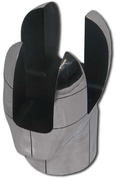
FIGURE D-2 U.S. Army Aberdeen Test Center headform. SOURCE: NRC (2012).
Per the test methodology, a helmet is placed over the clay-filled headform. RTP (or V0 testing) is then conducted as a sequence of five ballistic impacts, one each to the front, rear, left, and right sides of the helmet, and the helmet crown (Figure D-5). Internal Operating Procedure IOP PED-003 specifies the precise requirements for the five impact locations for V0 9-mm RTP/BFD testing. In addition, the ballistic forces from the bullet cause an indent in the clay from which BFD is measured. Current protocol also tests the V50 ballistic limit using a series of 6 to 14 shots to the five regions of the helmet at varying velocities per MIL-STD-622F (DoD, 1997). (See Chapter 6 for further discussion of the V50 calculation methodology.)
Appendix A of the DOT&E FAT protocol (DOT&E, 2010) specifies the distribution of helmet sizes and impact location order for V0, V50, and hardware testing. See Chapter 5 for additional discussion. The DOT&E LAT protocol does not specify helmet sizes, but impact location order for V0 testing is contained in Appendix B. See Chapter 7 for additional discussion.
TEST ITEM CONFIGURATION AND IMPACT LOCATIONS
To allow positioning the headform in the required positions, the headform used is mounted on a test fixture capable of being rigidly fixed with six degrees of freedom. Prior to mounting, the helmet is marked to show the impact locations and the helmet pads are put into a standard configuration, as illustrated in Figure D-6.
For V0 testing, the helmet is mounted on the headform in accordance with IOP PED-003 using the helmet’s suspension/retention system to hold it on the headform (Figure D-7). Per IOP PED-003, “The finished helmet will be mounted on the headform such that it has the standoffs given in table from the inside of the crown shell to the top of the crown clay” (ATC, 2013).
The headform is mounted on the test frame shown in Figure D-8. The helmet is aligned to ensure the target location achieves the required obliquity. During the test, the velocity of the projectile is measured using Oehler Model 57 Ballistic Screens to verify that it was within the desired range (NRC, 2010). A fair hit is recorded if the shot location, obliquity, yaw, and shot velocity are within required limits as specified in the DOT&E protocol (and associated reference documents).
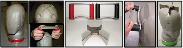
FIGURE D-3 Packing the headform with clay and shaping the clay. SOURCE: Kyle Markwardt, Test Officer, Aberdeen Test Center, “Helmet IOP PED-003 Briefing to NRC Helmet Protocols Committee,” presentation to the committee on March 22, 2013.
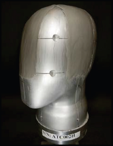
FIGURE D-4 U.S. Army Aberdeen Test Center headform with clay. SOURCE: Kyle Markwardt, Test Officer, Aberdeen Test Center, “Helmet IOP PED-003 Briefing to NRC Helmet Protocols Committee,” presentation to the committee on March 22, 2013.
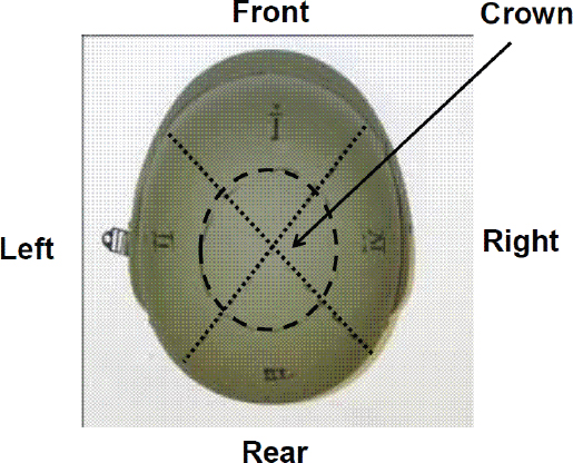
FIGURE D-5 Test impact locations. SOURCE: NRC (2012).
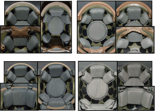
FIGURE D-6 Pad Configuration for V0 resistance to penetration testing for full cut style helmet (top) or the tactical cut style helmet (bottom). SOURCE: Kyle Markwardt, Test Officer, Aberdeen Test Center, “Helmet IOP PED-003 Briefing to NRC Helmet Protocols Committee,” presentation to the committee on March 22, 2013.
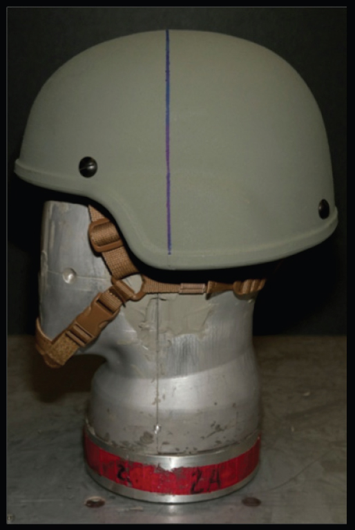
FIGURE D-7 Helmet mounted on a headform. SOURCE: ATC (2013).
Measuring Resistance to Penetration
In V0 testing, resistance to penetration is measured by visual presence of either (1) the projectile or pieces or fragments of the projectile in the clay of the headform (Figure D-9) or (2) by a hole that passes thru the helmet shell. For hardware and V50 testing, penetration is recorded via a witness plate inserted in the headform. See Figure D-10 for hardware testing and Figure D-11 for V50 testing witness plates. V0 testing is conducted with the helmet retention and pad systems in place, while V50 testing is conducted without the retention and pad systems.
Measuring Backface Deformation
Helmet BFD, defined as the maximum depth in clay as measured from the original clay surface at the intended impact location, is assessed using the nonperforating ballistic impacts from RTP testing. It is measured as follows. After mounting the headform in the test fixture and mounting the helmet on the headform, the helmet is removed from the headform, and the clay surface is scanned with a Faro® Quantum Laser Scan Arm laser. The helmet is then reattached to the headform, and the shot taken. The helmet is again removed from the headform and inspected for penetration and perforation. The clay is rescanned with the FARO laser to calculate BFD. Figure D-12 is an illustrative BFD indentation in the clay.
ATC IOP-002 revision E describes the BFD measurement process using a Faro scanning laser instrument scan
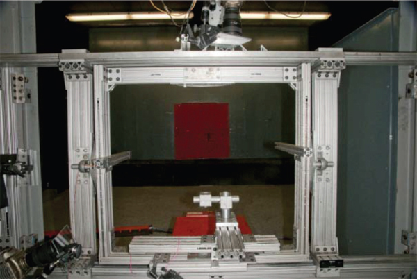
FIGURE D-8 Test frame and fixture. SOURCE: Kyle Markwardt, Test Officer, Aberdeen Test Center, “Helmet IOP PED-003 Briefing to NRC Helmet Protocols Committee,” presentation to the committee on March 22, 2013.
arm (Figure D-13) and associated software. As described in Testing of Body Armor Materials: Phase III:
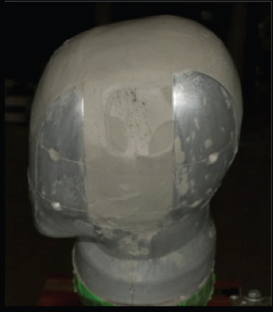
FIGURE D-9 Example of headform showing a penetration as evidenced by the presence of projectile fragments in the clay. SOURCE: ATC (2013).
Laser profilometry, as used by the Faro scanning laser instrument, employs the commonly used principle of optical triangulation. A laser generates a collimated beam, which is then focused and projected onto a target surface. A lens reimages the laser spot formed on the surface of the target onto a charge-coupled device, which generates a signal that is indicative of the spot’s position on the detector. As the height of the target surface changes, the image of the laser spot shifts owing to parallax. To generate a three-dimensional image of the specimen’s surface, the sensor scans in two dimensions, generating a set of noncontact measurements that represent the surface topography of the specimen under inspection. The data are then used to compute the three-dimensional geometrical profile of the surface, with readings essentially continuous over the scanned region. Thus, the laser scanner produces a series of measurements over the whole surface of the clay, as opposed to the single reading obtained with the digital caliper (NRC, 2010, pp. 97-98).
Clay Calibration
As described in the Phase II and Phase III body armor reports (NRC, 2010, 2012), the Roma Plastilina #1 clay currently being used to test helmets and body armor must be heated to achieve rheological properties consistent with past
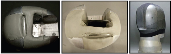
FIGURE D-10 Witness plate headforms for hardware testing. SOURCE: Kyle Markwardt, Test Officer, Aberdeen Test Center, “Helmet IOP PED-003 Briefing to NRC Helmet Protocols Committee,” presentation to the committee on March 22, 2013.
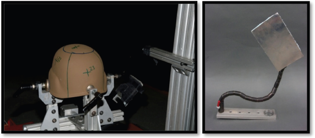
FIGURE D-11 V50 helmet test mount (left) and associated witness plate (right). SOURCE: ATC (2013).
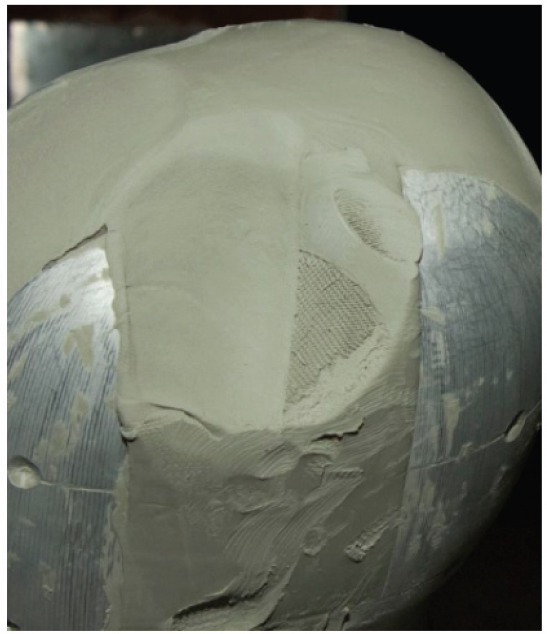
FIGURE D-12 Headform showing indent in the clay as a result of helmet backface deformation. SOURCE: Janice Hester, Research Staff Member, Institute for Defense Analysis, “DOT&E Helmet Test Protocols Overview: Statistical Considerations and Concerns,” presentation to the committee on January 25, 2013.
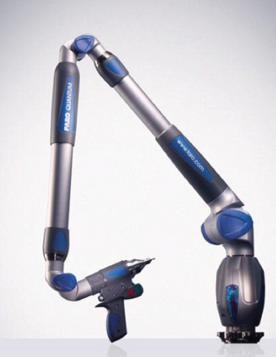
FIGURE D-13 Faro® scanning laser instrument laser scan arm. SOURCE: NRC (2012).
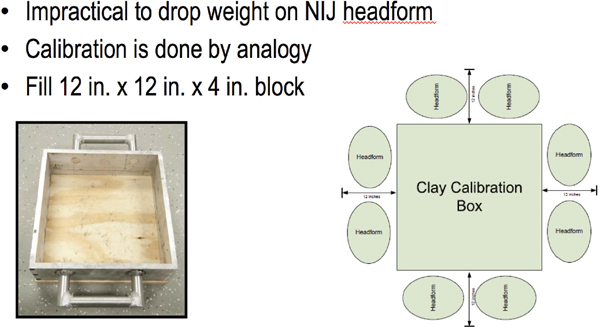
FIGURE D-14 Headform clay conditioning by analogy. SOURCE: Kyle Markwardt, Test Officer, Aberdeen Test Center, “Helmet IOP PED-003 Briefing to NRC Helmet Protocols Committee,” presentation to the committee on March 22, 2013.
tests. This occurs because the manufacturer has changed the Roma Plastilina #1 clay composition over time for commercial reasons unrelated to armor and helmet testing.
For helmet testing, the clay in the headform is calibrated by analogy to a reference 12 inch × 12 inch × 4 inch plywood-backed box of clay.1 Up to eight headforms may be conditioned with each box as long as the clay in the box and in the headforms come from the same lot and the headforms are conditioned within 12 inches of the box (Figure D-14).
Once conditioned, calibration of the box is performed via drop test in which 2.2-lb, 1.75-in.-diameter steel cylinders are dropped three times from a height of 78.7±0.8 in. into the clay box. The test rig is shown in Figure D-15. The clay is considered to be within calibration if the indentations made by the steel cylinders are all within 1.0±0.1 in. as measured by a digital caliper (NRC, 2012).
The first clay headform removed from the oven with the clay box may be used for up to 45 minutes after the third drop. The remaining headforms may be used for up to 4 hours from the time of the third drop and for up to 45 minutes after being removed from the oven (NRC, 2012).
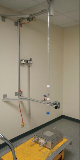
FIGURE D-15 Clay calibration test rig. SOURCE: ATC (2013).
__________________
1Kyle Markwardt, Test Officer, Aberdeen Test Center, “Helmet IOP PED-003 Briefing to NRC Helmet Protocols Committee,” presentation to the committee on March 22, 2013.
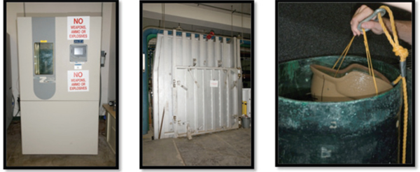
FIGURE D-16 Examples of helmet conditioning. SOURCE: Kyle Markwardt, Test Officer, Aberdeen Test Center, “Helmet IOP PED-003 Briefing to NRC Helmet Protocols Committee,” presentation to the committee on March 22, 2013.
Helmet Conditioning
First article testing requires ballistic testing after the following conditioning:
• Ambient: conditioned at 68 ±10°F and a relative humidity of 50 ±20 percent;
• High temperature: conditioned at 160 ±10°F for minimum of 24 hours;
• Low temperature: conditioned at –60 ±10°F for minimum of 24 hours;
• Seawater soak: fully submersed in 3 ft. seawater for minimum of 3 hours;
• Accelerated aging: 30-lb weight on the apex of the shell, conditioned for 4 hours at a temperature of 104 ±2°F followed by conditioning at a minimum ozone level of 50 +5 mPa partial ozone pressure for 72 hours; and
• Weather resistance: exposed to 100 kJ/m2 of energy.
See Figure D-16 (ATC, 2013, slide 17; Marqwardt, 2013, slides 23-26) for examples of helmet conditioning.
For additional details and information about the testing process, see ATC (2013), the documents listed in Table 1 of the DOT&E FAT and LAT protocols (DOT&E, 2010, 2012), and particularly MIL-STD-3027 [Department of Defense Test Method for Performance Requirements and Testing of Body Armor (DoD, 1997)], ATC-IOP-PED-003 (Helmet Testing Procedures), ATC-MMTB-IOP-002 Rev. E (Measurement of Backface Deformation (BFD) Using FARO Quantum Laser Scan Arm and Geomagic Qualify for Helmets), and ATC-MMTB-IOP-004 (Ball Bar Laser Scanning, Rev. A).
REFERENCES
ATC (Aberdeen Test Center). 2012. Helmet Ballistic Testing Procedures. Internal Operating Procedure PED-003. Aberdeen, Md. March 7.
ATC. 2013. “Helmet Testing Procedures.” Presentation to the Committee on Review of Test Protocols Used by the DoD to Test Combat Helmets on January 25, 2013. Available from National Research Council, Washington, D.C.
DoD (Department of Defense). 1997. Department of Defense Test Method Standard: V50 Ballistic Test for Armor. MIL-STD-662F. U.S. Army Research Laboratory, Aberdeen Proving Ground, Md.
DOT&E (Director of Operational Test and Evaluation). 2011. Standardization of Combat Helmet Testing. Memorandum from J. Michael Gilmore, Director. September 20, 2011. Office of the Secretary of Defense, Washington, D.C. [reprinted in Appendix B]
DOT&E. 2012. Standard for Lot Acceptance Ballistic Testing of Military Combat Helmets. Memorandum from J. Michael Gilmore, Director. May 4, 2012. Office of the Secretary of Defense, Washington, D.C. [reprinted in Appendix B]
NRC (National Research Council). 2010. Testing of Body Armor Materials for Use by the U.S. Army—Phase II: Letter Report. The National Academies Press, Washington, D.C.
NRC. 2012. Testing of Body Armor Materials: Phase III. The National Academies Press, Washington, D.C.


