
5
Mathematical Models
Many components of shiphandling simulators are substantial physical pieces of hardware. Some components can be evaluated easily from their appearance (the bridge and its equipment) or performance (the size, resolution, or update rate of the display). The mathematical model, which is embedded in the simulation computer and invisible to the user, is difficult to generate and even more difficult to validate. This section describes the state of practice of the development of the computer-based model for a shiphandling simulator. Validation of the model is presented in Chapter 6.
SELECTING AND IDENTIFYING THE SIMULATION MODEL
Before a simulation can be performed, it is necessary to develop quantitative computer-based models for the waterway, ship, and various components of the traffic. Each of these models consists of two kinds of information:
-
a framework (or structure) for the data (which describe the generic component), and
-
a set of numerical constants associated with the framework.
The framework is a widely applicable mathematical procedure or algorithm that embodies the relationships between the various factors involved. Numerical constants or coefficients quantify these relationships for the spe-
cific case under consideration. Selection of a particular framework for a specific component varies from facility to facility, is usually based on theoretical developments associated with that component, and is usually proprietary. Determination of the numerical constants associated with the framework is called identification. A discussion of both the selection of a framework and identification of its constants for each major component of the computer model is presented in the following sections.
WATERWAY BATHYMETRY
In order to determine the forces that act on a ship, it is necessary to determine the bathymetry (depths, contours) of the waterway in the neighborhood of any position the ship might assume during its passage. The framework typically consists of a data base that stores the waterway depth at specific locations and an interpolation scheme for these data that allows estimation of the water depth at an arbitrary point in the waterway. The structure of these data bases varies considerably. No clear advantage has been demonstrated for any particular scheme. Usually selection is a tradeoff between size of the database and ease of interpolation, which translates into a tradeoff between the storage capacity and computational speed of the computer used for the simulation. The presentation of the data in the original source is a strong influence on the selection of framework.
A typical framework for the data base is a grid on a chart of the waterway (either a rectangular grid or curvilinear grid fitted to the channel). Entries in this matrix correspond to water depth at each node of the gird. Data points must be specified with sufficient density to capture the underwater geometry of the waterway. Of the various choices, the rectangular grid (normally based on latitude and longitude) requires the largest number of data points but is simplest for interpolation. Data bases that use a waterway-fitted grid (for instance, one that uses the channel centerline as one coordinate) are much smaller but require more complex interpolation.
In any of the grid data base systems, different levels of interpolation can be used. Linear interpolation is the easiest and has the advantage of being most computationally robust. However, linear interpolation is also the least accurate because the interpolated values always lie within those data base values used as input to the interpolation. Higher order schemes, such as parabolic interpolation or cubic spline interpolation, require fewer data base points. However, if the data base points do not correspond to a smooth surface, anomalous interpolations can occur. Consequently, linear interpolation is most often used.
Some facilities use a different system altogether, one in which the numbers stored in the waterway data base correspond to polygonal contours of equal draft. Although this scheme results in an extremely compact repre-
sentation of the bathymetry of the channel, it also results in the most computationally demanding interpolation scheme. The bathymetry of very complicated waterways can be described to the degrees of accuracy necessary with either the grid system or the contour system. Increases in accuracy require corresponding increases in the amount of stored data in the data base regardless of the interpolation scheme used.
Identifying actual data for the data base is not always easy or straightforward. Typical proposed waterway modifications usually involve some widening and deepening of existing channels or perhaps changing the channel path. Some projects involve dredging channels where none had existed before. In cases where the channel dimensions of a new design are specified, the bathymetry can be read directly from the plans for the waterway.
Much of the overall project area may be in a natural state or may be the result of previous dredging. Many available charts of waterways are not recent, and few of these include information on water depth that is dense enough for an adequate data base. Most field survey records provide discrete soundings at specific data points rather than a continuous bottom profile. About 60 percent of field surveys conducted by the National Oceanographic and Atmospheric Administration (NOAA) were done prior to 1940 with lead lines (NOAA, unpublished data).
Waterways are not static; they are constantly changing. Some bathymetric changes are due to seasonal variations of flow, others may be part of variations resulting from singular events that occur every few years (for example, floods), and still others represent long-term trends that may span decades, if not centuries. Investigation and correction of chart discrepancies reported by various sources are backlogged, with about 20 thousand discrepancies remaining unresolved in backlog during early 1991. NOAA can field investigate about 20 percent of chart corrections, which leaves major areas with unresolved discrepancies. As a result, reliable continuous bottom profiles are available for only some of the important shipping routes along the coasts and in ports and waterways (NOAA, unpublished data). Therefore, developing a bathymetric data base requires careful research and may well require the supplementation of information on available charts with in situ measurements. It should be noted that the density of bathymetry data points required for determining channel flow and grounding is more demanding than that required for determining of the forces on a ship (Norrbin, 1978; Norrbin et al., 1978).
WATERWAY ENVIRONMENT
Because of the efficiency that results in the computer programming, the data base framework selected for the waterway environment is usually identical, or at least corresponds quite closely, to that for the waterway bathym-
etry. In this way, similar interpolation schemes can be used for both. However, determining the waterway environment data base is fundamentally more complicated than for waterway bathymetry. Those quantities that describe the environment, such as wind, current, and density, often vary with time of day or season or with altitude or depth in the waterway. For existing waterways, information on existing charts regarding currents is typically even less detailed than that for bathymetry, and information on other quantities is even more sketchy. For waterway designs involving changes in existing bathymetry, information on current variations needs to be developed.
The waterway environment can reflect some unique problems. In some cases, a density stratification may exist (for instance, at a river mouth where fresh water may override a saltwater wedge). In such cases, the variation of current with water depth can even include a reversal of the flow. Similarly, air characteristics, such as velocity, turbulence, and temperature, can vary with weather or with altitude above the waterway and can be significantly different in the shadow of buildings or bridges than elsewhere. Design-related bathymetric changes relative to the tidal prism in coastal ports may also affect sedimentation rates and, consequently, waterway operations and maintenance. Data on such effects are generally not available, but depths could be changed in the simulation to obtain a rough estimate of behavioral changes in the design ship when sedimentation modifies the bottom profile. However, there is no indication that maintenance factors have been incorporated into most simulations.
The database for the environment can be formed in several ways. For an existing waterway, a field survey can be conducted to determine the values in situ, but the cost of such a survey may be high. Hydraulically scaled models are traditionally used either as a less-expensive alternative to in situ measurements in existing waterways or as a way to determine the flow in waterways not yet built. These models usually predict reliably the gross characteristics of horizontal flow. However, due to difficulties in scaling viscous effects, predictions of vertical variation of fluid velocity at any given point are less reliable.
Computational fluid dynamics (CFD) schemes have been developed in the past decade to predict currents in waterways with complicated bathymetry. Already these methods are less expensive to use than physical models. As with physical models, CFD schemes yield better results for the average horizontal fluid velocity than they do for the vertical fluid velocity distribution at a given point. However, both hydraulic models and CFD schemes can benefit from comparison with in situ measurements.
It is very difficult to determine the variations of the waterway environment that occur with depth or altitude. More importantly, no validated means exist for predicting the effect of these variations on the forces acting
on the ship. Therefore, it is typical to replace the variation of current with depth or the variation of wind velocity with altitude by a single, uniform current or wind vector that will produce approximately the same force distribution on the vessel. In this case, the actual value of the current that is not depth dependent may be entered into the data base and is chosen carefully to reflect the more complicated character of the actual flow. In particular, the value appropriate for one ship loading and draft may not be appropriate for the same ship at a different loading and draft.
Some facilities retain the vertical variation of the current with depth in their data bases and estimate the effective value of the current as a value of current averaged over the actual ship draft at the given location. This scheme requires a much bigger data base and more computation, but it has the advantage of not requiring revision if a different ship or ship loading is used for the simulation. Finally, there is usually not one but a collection of environmental data bases, each reflecting a given state (phase of the tide, current distribution, and weather).
MATHEMATICAL MODEL OF SHIP DYNAMICS
The framework for the theoretical model of ship dynamics was described in general terms in Chapter 3. It involves two separate pieces: Newton's equations of motion (as modified by Euler for moving bodies) and a representation of the forces acting on the ship as a function of its orientation in the waterway and with respect to environmental conditions. The Euler equations of motion have a sound scientific base. The coefficients associated with these equations are easily identified and are therefore not discussed further in this report. Essentially there is no variation in this part of the framework from one facility to another.
Because Euler's equations are not in question, the accuracy of the mathematical model of ship dynamics is governed by the ability to predict the instantaneous force system on the ship. (For brevity of discussion, this report does not distinguish between forces and moments, referring to both simply as forces). The forces acting on the ship arise primarily from the combined effects of water surrounding the ship, wind, waterway geometry, and other external forces such as tug boat assistance and riding on anchor (Abkowitz, 1964; Bernitsas and Kekridis, 1985; Eda and Crane, 1965; Norrbin, 1970). Most of the complexity (and uncertainty) of a mathematical model for the behavior of a ship stems from the estimates made for this force system. Considerable variation exists from one facility to another because representations of the forces that act on the ship are complicated and do not have the firm scientific basis of Euler's equations.
The dynamic framework is usually separated into several manageable constituent parts (or modules), which are dealt with relatively independent
ly as shown in Figure 5-1. The separation of the ship hydrodynamic forces into those in unrestricted shallow water and corrections to account for restrictions, such as banks, reflects the historical development of mathematical modeling of maneuvering ships over the last 100 years. Figure 5-1 depicts three threads of information (represented as thick horizontal lines) that affect several modules within the ship model. Two of these, the commands from the pilot and the position and velocities resulting from the ship's behavior, are available outside the ship model. The third, which is the sum of instantaneous forces on the ship, is part of the necessary internal bookkeeping for computing the ship's motion.
In many simulators, only three degrees of freedom are used (surge, sway, and yaw—the so-called horizontal motions) because the vertical motions interact little with the steering and maneuvering characteristics of the ship. In a severe turn, the ship roll angle may become large for ships with small inherent roll stability. The angle of roll changes the wetted hull shape. This can substantially increase the turn radius. Where the underkeel clearance is small, the vertical motions (heave, pitch, and roll) can
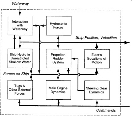
FIGURE 5-1 Schematic diagram of modules in simulated ship behavior.
have an important effect due to the combined effects of squat and the response to waves, currents, or wind. In these circumstances, all six degrees of freedom are used.
COMPONENTS OF THE FORCES SYSTEM
In the following sections, various components of the forces system acting on the ship are discussed in general terms, including approximations used for application in a simulator and the identification of numerical parameters. Characterization of the hydrodynamic forces on the ship is usually treated as a variation and expansion of the classical treatment of steering and maneuvering in deep water. Therefore, the deepwater problem is discussed first, even though it is not applicable to typical waterway design. Components are also discussed in relation to unrestricted shallow water, restricted shallow water, rudder-propeller systems, and propulsion and steering systems.
Specific equations are not introduced in the following sections. The mathematical presentation of any of these models is algebraically intensive, as demonstrated by a mathematical model for the Esso Osaka in unrestricted shallow water (for further information on Esso Osaka, see Abkowitz, 1984; Ankudinov and Miller, 1977; Crane, 1979a,b; Dand and Hood, 1983; Eda, 1979b; Fujino, 1982; Gronarz, 1988; Miller, 1980; Report of the Maneuvering Committee, 1987).
Deepwater Factors
Measurement of the steering and maneuvering characteristics of ships in deep water is a well-understood and highly developed technology. Most facilities use a history-independent formulation where the forces are assumed to be approximately the same as those that would exist on a ship that has been in the same situation for a long time. Forces acting on the ship are assumed to depend only on the instantaneous attitude velocities and accelerations of the ship (referred to simply as the instantaneous state of the ship). It is assumed that these forces do not depend on the motions of the ship or its attitude at previous times. Indeed, memory effects are a well-known phenomenon resulting from the wave system and viscous flow created by the ship's forward way and by wave-induced motions, and these effects are important in predicting the oscillatory motions of a ship due to a seaway. However, time scales for the steering and maneuvering problem are so large that these memory effects are unimportant in this context.
The framework usually consists of a polynomial representation of the forces in terms of the instantaneous displacements, velocities and accelerations of the ship, propeller, and rudder (and various products of these mo-
tions). This polynomial can be viewed as a truncated, multivariate Taylor's expansion about the state of the ship, which corresponds to straight-line travel at a constant forward speed. This representation does not embody any physics per se, but simply reflects an implicit assumption that these forces vary smoothly with the state of the ship. The expansion is truncated to include only those higher-order terms that appear to yield significant forces. Quantification of the framework is obtained by identifying the coefficients of each term in this polynomial. In fact, many different mathematical frameworks are used at simulation facilities around the world, and each facility appears to have its favorite. Most of these frameworks are identical in their linear terms and in many of their nonlinear terms. Differences occur in the number and type of higher-order (that is, nonlinear) terms that are retained. However, it should be noted that the numerical values of the coefficients associated with the linear terms depend on which nonlinear terms are retained in the framework.
The coefficients that relate instantaneous motions to forces acting on the ship are most often determined experimentally by captive model tests using either an apparatus called the Planar Motion Mechanism (PMM) or a special facility called a rotating arm basin. These tests are performed by oscillating a laterally restrained scale model of the ship in question in sway and yaw at Froude-scaled test conditions. It is assumed that viscous effects (which are not scaled in the model tests) can either be ignored or corrected for. Analysis of the time histories of the forces acting on the ship model resulting from many captive model tests is used to determine both linear and nonlinear coefficients in a mathematical model for these terms. These coefficients are obtained by a multivariate regression or by curve fitting, depending on the conduct of the captive model test. In addition, tests are performed with the rudder at various angles and the propeller at various rotational speeds. Changes in forces and moments resulting therefrom are also identified by coefficients in polynomial framework.
The mathematical model for hydrodynamic forces and moments is joined with Euler's equations of motion and a model for the dynamics of the propulsion system (discussed separately below) to form a simulation model for deep water. This model can be used for simulating steering and maneuvering exercises in deep water and for training of a ship's bridge team. Such models have been used by Japanese shipbuilders, for instance, to select the size and location of rudders in new tanker designs.
Because captive model tests are expensive and time consuming, many facilities have built up libraries of dynamic data on previously tested models. These data have been used by some of these facilities as a data base from which the coefficients in the mathematical model for ships can be estimated by regression (that is, without a physical model test). Presumably, if the data base were large enough, this approach would be successful.
However, most facilities do not release their data, and thus, it is difficult to judge the success of this process.
In recent years, an alternative scheme called systems identification has been devised for determining the coefficients in the mathematical framework for all the hydrodynamic forces, including the propeller and rudder (Abkowitz, 1980; Aström et al., 1975). In this scheme, a free-running model (or full-scale ship) is instrumented to record both the motions and inputs (for example, rudder angle, propeller revolutions per minute [RPM], speed, heading). This information together with a proposed framework is used to ''identify'' the numerical value of the coefficients and to give a measure of "goodness of fit." The mathematics are too involved to attempt to describe in this report. If these data are taken on a model, then some correction for the viscous effects may be called for; if these data are taken on the full-scale ship, then the coefficients may be used directly. Some indications suggest that this approach can be as successful as using captive model tests, although the systems identification approach typically identifies fewer coefficients than are used in the traditional approach.
Interestingly, neither analytical hydrodynamic analysis nor computer-based algorithms (CFD codes) are sufficiently mature to predict coefficients for use in steering and maneuvering models from the underwater geometry of the ship, even for this simplest case of deep water. The difficulty lies in the fact that viscosity has important effects and cannot be ignored. Advances are being made in developing computer-based programs for treating viscous free-surface flows. However, these programs may be as expensive to run as physical model tests, and their ability to reproduce physical model test results has not been demonstrated.
The simulation of steering and maneuvering in deep water appears to be satisfactory for engineering applications, as long as the coefficients of the mathematical model are identified by a properly conducted physical model test. Using a data base of test results to predict the coefficients of a ship without a model test may be acceptable for most waterway work (Clarke, 1972; Kijima et al., 1990).
Unrestricted Shallow Water
The maneuvering of ships in unrestricted shallow water (water of a depth less than 2.5 times the vessel draft of infinite lateral extent) has been investigated much less than that of deep water. The flow around a ship becomes dependent on the water depth, and this additional parameter makes both theoretical developments and experiments much more difficult. Nonetheless, nothing about these experiments makes the interpretation of the results more complicated or more difficult than the deepwater case, except in the instance of extremely shallow water where the viscous flow under the
ship's bottom may not be modeled well in small-scale experiments. In particular, the same mathematical framework typically is adopted for the force model, with perhaps a few more nonlinear terms included to capture forces that are important in shallow water but are inconsequential in deep water.
Several experimental studies have been performed in moderately shallow water, and their results are surprising. Whereas the force coefficients in the mathematical framework vary smoothly with water depth, some of the handling characteristics do not. For instance, several researchers using model tests found that ship turning performance first improves upon entering shallow water and then degrades rapidly as the under-keel clearance becomes very small (Crane, 1979a; Fujino, 1968, 1970). This finding suggests that the effect of very low under-keel clearance can be dramatic and cannot be ignored. No measurements, full or model scale, have been made in the range of 10 percent under-keel clearance or less, a range commonplace in U.S. ports (National Research Council, 1985).
To obtain experimental data for use in the mathematical framework, it is necessary to run the same type of PMM tests or systems identification study for deepwater cases, but at several finite water depths as well. This approach requires a test basin where the bottom is extremely flat; few such basins exist worldwide. As a result, very few ship models have actually gone through extensive shallow water maneuvering testing, and the data are sparse. Available data have been referred to extensively.
The situation in unrestricted shallow water is similar to that in deep water. However, not all the phenomena are clear. To perform either physical model tests or full-scale trials would require addressing significant modeling questions concerning the viscous flow in the gap between the ship and bottom and concerning the deformation of the mud bottom by the ship. The cost of performing the required tests is high because a new test parameter (water depth) must be varied. The lack of a flat bottom at most facilities has inhibited the testing of ship models with under-keel clearances comparable to current ship traffic. With the help of some theoretical developments, most ship model testing facilities have developed proprietary, semiheuristic schemes to modify deepwater maneuvering coefficients so that they are approximately correct for shallow water.
Restricted Shallow Water
The preceding discussion of the ship model focused on maneuvering a ship in unrestricted, quiescent water of finite depth. However, many other interactions need to be considered if the simulator is to be useful in waterway design. Interactions include the force system on a ship maneuvering in a channel with geometric complexity (turns, banks, uneven bottom, and so
on), with hydrodynamic complexity (complex current patterns, tidal variations, and so on), and with atmospheric disturbances. It is convenient to separate differences in these areas into two force systems: one resulting from the atmospheric environment and the other resulting from the water environment. Interactions due to other vessel traffic and the use of auxiliary help, such as tug boats, also need to be considered.
The effect of wind, resulting from both the average velocity and gusts, can be important in some waterways. Wind forces become relatively more important when the vessel has small forward movement, when the vessel has a large "sail area," or when it has a shallow draft. Sail area is affected by hull and superstructure configurations, freeboard, and deck cargo such as containers. With loading, the sail area of a tanker decreases, and its draft increases, making a fully loaded tanker less susceptible to wind effects. A containership loaded with empty containers that are stacked high on deck may have both a large sail area and a small draft, and thus it is very vulnerable to wind effects. When the wind is parallel to the channel and in the same direction of travel as the ship, controlling the forward movement can be difficult, especially for diesel-powered ships where the minimum sustainable RPM corresponds to a significant speed and where the number of air starts may be limited.
Significant wind forces usually arise when the wind velocity is much greater than the ship velocity, and as a result, a simple framework for these forces is usually adopted. Aerodynamic forces are estimated using an empirical drag coefficient dependent on the relative wind direction. The effects of gusty conditions are usually included as an increment to the average wind velocity.
The framework for the hydrodynamic forces is a set of equations used to predict the changes between the force system resulting from these interactions and the force system that would exist in unrestricted shallow water of the same depth. This framework usually has the same general polynomial format as that used for hydrodynamic forces in unrestricted shallow water. The coefficients now depend, however, on the distance to, and the character of, the bank and other obstacles.
This force system consists of steady forces and unsteady forces. Steady forces are typically due to an interaction with a bank. When the ship is travelling parallel to the bank, force is directed toward the bank (so-called bank suction forces), and the moment results in a bow out movement. However, at other angles, changes in these forces can be either toward or away from the bank. Propeller revolutions can also affect these forces in the presence of a bank. A considerable body of literature on these steady forces exists where the results of experiments are reported (Norrbin, 1970, 1978). Empirical formulas have been developed that are successful for predicting them.
Unsteady forces are usually separated into two types. The first or
quasisteady force system represents a modification of the steady force system due to the instantaneous motions of the ship due to the proximity of restrictions. The second or fundamentally unsteady force system represents the transient forces that result from the ship approaching a bank or obstruction, passing by a discontinuous bank, passing another ship (either on reciprocal courses or overtaking), or passing into an area where the water depth changes suddenly or the water current varies dramatically in speed or direction (see Armstrong, 1980; Crenshaw, 1975; Plummer, 1966).
The quasisteady force system arises when the ship is traveling, on the average, parallel to a continuous bank of uniform geometry in a region and where the depth changes are very gradual and the current is nearly constant in speed and direction. In this case, motions arising from course keeping can be considered as small perturbations about an otherwise steady flow. The quasisteady force system is usually characterized by the same framework as that for unrestricted shallow waters, except that the coefficients must include an additional parameter: the distance from the bank. Coefficients in this framework depend not only on water depth and ship geometry, but on current in the waterway and geometry of the bank as well (Abkowitz, 1964). For this situation, it is also possible to perform PMM testing at several different water depths and, at each of these depths, perform additional testing at several different distances from the bank. However, the number of variables involved make the cost of this type of model test program high. Thus, such tests are almost never conducted to identify these coefficients. Nevertheless, some tests of this type have been performed, and results are available in the literature (Abkowitz, 1980; Eda et al., 1986; Norrbin, 1978).
When the ship is not traveling approximately parallel to the channel or is oriented to other traffic so that the flow is fundamentally unsteady, it is impossible either to eliminate time (that is, history) from the problem or to reduce the transient force system to simple time-independent coefficients. The most studied of these fundamentally unsteady phenomena are cases of ships passing interrupted banks, ships approaching banks, and ships passing one another (Dand, 1984). The literature in this area is very limited, and most of the data that are available are for the passing ship case.
Experimental studies have been conducted on the effect of interrupted bank systems where the interruptions are in a straight line (Norrbin, 1974, 1978). Reducing these data to numerical formulas appears to have been accomplished by various facilities using proprietary techniques. The effect on the force system due to sudden changes in waterway depth, to a waterway bathymetry that is truly three-dimensional, or to currents that vary significantly along the length of the ship apparently have not been systematically studied. However, mathematical simulation models typically ignore or only crudely approximate the effects from this kind of temporal or spatial
dependence. The computation of this representative value from the instantaneous state of the ship and its position in the waterway is heuristic and varies considerably from facility to facility.
Model tests to determine the force and moment history of two ships passing one another have been conducted in several contexts and particularly for the Panama Canal study (see Appendix C). The overtaking configuration is, in general, the most severe because the time during which the interaction between vessels may be strong is far longer, although studies of meeting situations are more common. Interaction forces between the two hulls will cause perturbations in the trajectory of both ships, particularly if the waterway is narrow (Gates, 1989; Hooyer, 1983; Plummer, 1966).
Potential parameters in such a study are numerous and include the description of the two ships, each of their speeds, initial passing distance, passing angle, water depth, and distance to a bank. Parametric tests to investigate each of these variables appears feasible, but such tests probably would be prohibitively expensive. The usual practice (when passing tests are conducted at all) is to measure the force system when passing ships are constrained to straight-line motion. Fundamentally unsteady forces and moments are measured, but deviations of the ships' tracks in response to these forces are not allowed. These responses may be significant, especially when the passage is a close one or when ships are in an overtaking configuration (where the exposure time is long). Typically, constrained model test data are used, together with empirical or heuristic corrections, to predict the force and moment history for the actual passing condition.
A body of theoretical literature also exists based on a linear (small motion) analysis of a ship passing a bank or other objects (Yeung, 1978). These theoretical developments often are used to establish framework elements of the unsteady waterway interaction framework. Coefficients associated with this framework are usually identified using the above-mentioned experimental results available in the literature, modified to account for differences between the ship under consideration and the ship that was tested. These semiheuristic methods are almost always proprietary to the individual facility.
Finally, there are other possible important interactions that may be required for certain simulations. Tug boat assistance is a feature of many maneuvering situations. The presence of tugs alongside a larger ship is, like the passage of ships, a situation where a strong interaction is expected in principle. However, because these tugs are typically much smaller than the simulated ship, their principal interaction is through the thrust (both size and direction) generated by the propeller-rudder combination (Brady, 1967; Dand, 1975; Reid, 1975, 1986). In general, this interaction is directed by the pilot or master of the simulated ship, and the modeling of this interaction is typically treated in a quite simple fashion.
Rudder-Propeller System
This force system module represents the combined effects of the propeller and rudder, which are usually treated together because they are the primary actuators for steering and maneuvering. Rudder angle, propeller RPM, and propeller pitch (if the propeller is variable pitch) are introduced as new variables, and the forces resulting from the interaction of propeller, rudder, and hull typically are characterized by them. Because these forces also depend strongly on the flow about the basic ship, formulas for these forces also involve the state of the ship and its geometry (particularly the after body).
The force and flow field produced by a propeller driving a ship at constant speed are relatively well known, and means for its prediction are available. The force and flow field created by a propeller spinning at a speed different from these equilibrium conditions is less well known, especially when the ship is maneuvering and the propeller may be spinning with a rotation that would ultimately cause the ship to reverse its present direction. Four separate situations with regard to propeller operation can be identified, depending on the sign of the velocity of the ship (either ahead or astern) and the sign of the propeller rotation (either in the ahead direction or the astern direction). These four situations are usually called quadrants, because they appear on a graph of ship speed along one axis, and propeller RPM appears along the other. Characterizing the effect of the propeller for all possibilities of ahead and reverse propeller rotation, and forward and astern ship's velocity (the so-called four quadrant problem) is difficult. Most simulators do, however, include an approximate model for these conditions.
The side forces on a rudder are usually proportional to rudder angle when small rudder angles are used, but depend in a more nonlinear fashion for large rudder angles. Side forces on a rudder also depend approximately quadratically on the flow velocity over the rudder, and thus, the hydrodynamic effects of the propeller and rudder are fundamentally linked. When the ship is proceeding ahead and the propeller is rotating to maintain this motion, flow over the rudder is typically at a somewhat higher velocity than the ship's velocity. However, if the pilot decides to execute a full-astern maneuver (or the pitch of the propeller is reversed), then flow through the propeller is ultimately reversed, and the rudder may experience little or no flow over it. This situation is often referred to as blanketing the rudder and results in the rudder being almost ineffective. A characterization of these effects using elementary hydrodynamic analysis and empirical results is usually included in a semiempirical model for the propeller-rudder system.
Various facilities differ in their approach to quantifying propeller-rudder interactions. Because a Froude-scaled ship model does not reproduce
the viscous effects properly, a self-propelled ship model cannot behave as the full-scale ship would. That is, the propeller in a self-propelled ship model has to produce considerably more thrust to overcome the relatively greater viscous drag of the model. The propeller-rudder interaction forces are often measured on a captive, towed model with the propeller spinning at a range of RPMs and at various rudder angles. The results are scaled up to full scale using the information from separate propeller tests using larger models, performed in a facility called a propeller tunnel. This type of facility models the atmosphere so that important effects of cavitation can also be modeled and observed.
The cost of experimentally determining influences of the propeller and rudder is high. Many facilities use empirical formulas based on previous model tests to estimate the four-quadrant behavior of the propeller and its interaction with the rudder.
Additional modules are often added to account for other maneuvering devices, such as thrusters, if they are installed. Characterizing these devices and their interaction with the hull is in principal very complicated. As a result, a semiempirical approach is usually adopted.
Model of Propulsion and Steering Systems
The propulsion and steering systems are also critical to maneuvering a ship, because the propeller RPM and rudder angle are determined by them. They are also mechanical devices with their own dynamics. These devices cannot respond instantly when commanded because of their own inertias and other limitations. A detailed characterization of these maneuvering elements would involve developing equations of motion that reflect the physical properties or response of many individual components. Steering gears and thrusters have relatively straightforward mechanisms, and they apparently do not require great sophistication in the mathematical model to capture their behavior.
Characterizing the main propulsion system behavior is, however, more difficult because typical systems are large, have substantial inertias, and involve many components, particularly for diesel systems. The propulsion model (usually referred to as the engine model) also requires characterization of the torque characteristics of the propeller as a function of its RPM. Two choices are typical for main propulsion: steam turbines and diesel engines.
Steam turbines have few moving parts in the main drive train to model. These include the rotary inertia and friction of the turbine rotors, gear system, line shafting, and propeller. Because these elements are geared together, they are dynamically equivalent to a single rotating mass. These characteristics result from the thrust the propeller produces and its hydrodynamic
losses. In addition, dynamics involving the steam valves and associated equipment may be important. Models for complete steam turbine power plants are somewhat complex, but reliable models have been constructed by several different facilities (van Berlekom and Goddard, 1972).
In today's fleet of merchant ships, diesel engines are much more popular choices for the main propulsion plant and are, unfortunately, much more difficult to characterize. Large, direct-connected diesel engines typically have 6 to 12 cylinders and are equipped with many auxiliary mechanical components, such as turbosuperchargers. The sheer number of moving parts in such an engine and the associated degrees of freedom preclude direct modeling of the intercoupled mechanics of each component. Rather, an indirect, behavioral model is usually adopted, where the engine in toto is replaced by an equivalent dynamic system with only a few degrees of freedom and with inertias and damping chosen to mimic the behavior of the diesel engine.
In addition to the mechanical modeling of the main elements of a diesel engine, other modeling problems exist. Starting and reversing these machines are achieved by injecting compressed air into some of the cylinders. Although this process is fairly reliable, failure to restart is not uncommon, especially in cold weather. Thus, a random delay may occur in the reversal of the engine. Further, some diesel engines have a finite reserve of starting air, and the reversal-restart cycle may become compromised if many such maneuvers must be performed in close succession. During changes in power level for some configurations of diesel engines, a significant lag may also occur in the air boost pressure due to the dynamics of the turbosupercharger-air plenum system. Thus, modeling the dynamic performance of a diesel engine during maneuvering is a significantly greater challenge than modeling a steam turbine, and the state of the art is not as well developed (Eskola, 1986).
SUMMARY
The mathematical model used for shiphandling simulation consists of not one model, but a series of many models, each representing a particular piece of hardware or important physics. These models are interconnected inside the computer that runs the simulator to reflect the physical interactions among the elements they represent. Each of these component mathematical models has its own set of uncertainties resulting from the modeling process, and it is difficult to assign an uncertainty for the overall model. The model that predicts the hydrodynamic forces on a ship as a result of its motions and proximity to the bottom, banks, and other waterway features is perhaps the most difficult to develop, and its uncertainty is greatest in the case of shallow, restricted channels.


