
3
Physical Properties and Fundamental Processes in Fractures
To build predictive models and understand the behavior of complex fracture systems it is necessary to understand the behavior of a single fracture under the same in situ conditions imposed on the whole system. This is true whether the fractures are represented explicitly, as in a network model, or implicitly, as in a stochastic effective medium model.
Two questions are the focus of this chapter: (1) How do flow and transport occur in a single fracture, and what factors significantly affect flow and transport properties? (2) What are the geophysical characteristics of single fractures that make it possible to detect and characterize them remotely?
This chapter emphasizes the results of theoretical and laboratory investigations. Theoretical studies, in combination with controlled laboratory tests, provide the fundamental physical properties and relationships between parameters that describe the processes of fluid flow and transport, seismic wave propagation, and electrical conduction. These fundamental relationships can then be incorporated in models of natural, more complex fracture systems. In laboratory studies, initial and boundary conditions can be controlled and experiments constructed in order to study the effects of a single or limited number of parameters. It should be noted that the physical properties of systems of fractures may be more complex than a simple linear superposition of the properties of single fractures, especially when the fractures intersect. Nonetheless, laboratory experiments can provide the basis for understanding the phenomena that govern large-scale field experiments of fracture systems.
This chapter begins with a discussion of the geometry of a single fracture and the effects of stress and genesis on that geometry. This is followed by a discussion of flow and transport and, finally, of geophysical properties.
GEOMETRIC PROPERTIES AND STRESS EFFECTS
Although fractures are often visualized conceptually as parallel plates separated by some distance (the ''aperture"), there are few situations under natural conditions in which this conceptualization is accurate or meaningful. Generally, in the plane of the fracture there are regions in which the surfaces are in contact and regions, or voids, where the surfaces are not in contact. The factors that most affect the geometry of the void space are (1) the geological origin of the fracture (see Chapter 2); (2) the subsequent changes in stress brought about by natural processes and the activities of humans, such as withdrawal or injection of fluids or construction of underground openings (see Chapter 7); and (3) mineral precipitation and dissolution as fluids flow through a fracture (see Chapter 7).
The voids of a fracture form an interconnected network through which fluid flows. The concept of a fracture as a planar network of interconnected voids leads to an analogy with porous media. In fact, a better conceptualization of a fracture is that of a two-dimensional porous medium in which the fracture voids represent pores. The two-dimensionality arises because all the connections between the fracture voids are in the plane of the fracture.
There is an important difference between fracture void structure and pore structure that limits the extent of this analogy and leads to important differences in hydrological behavior between fractures and porous media. Whereas the bulk of the flow is carried in the large void spaces in both fractures and porous media, the fracture voids tend to be more cracklike in shape compared to the equant shapes of voids in porous media. Cracklike voids deform more easily under applied stress than equant voids. Consequently, the hydrological properties of fractures are subject to a much higher degree of stress sensitivity than porous media. Because fractures represent discontinuities in material properties, shear stresses can also result in deformations, leading to large changes in hydrological properties. Stress sensitivity constitutes the single greatest distinction in hydrological properties between porous media and fractures.
Another consequence of the two-dimensional nature of fractures is that flow can easily become channelized and under two-phase conditions can lead to strong phase interference. Because the pore structure is two-dimensional, flow only has the plane of the fracture to find a path around the closed void (if the matrix rock is impermeable). In porous media (or if the matrix rock is significantly permeable) the third dimension is also available.
One focus of this chapter is the effect of stress on both hydrological and geophysical properties. Fundamental to understanding these effects is a knowledge of how fracture void geometry changes under generalized stress conditions. Thus, the mechanical deformation of fractures is discussed in this section; the effects of this deformation on fluid flow and geophysical properties are discussed in subsequent sections.
The dimensions of the voids in the network certainly affect flow, but of equal if not greater importance is the connectivity of the network. At the most
fundamental level, flow and transport in a fracture are controlled by the geometric properties of the interconnected voids in the fracture. This section will first discuss these geometric properties from a purely descriptive perspective. Then the changes that occur in geometry as stresses are changed will be described.
Roughness of Fracture Surfaces
A fracture can be envisioned as two rough surfaces in contact. If the surfaces are not perfectly matched, as would be anticipated in many natural environments, there will be some regions where voids remain. Because the void space arises from a mismatch at some scale between the two surfaces of a fracture, a great deal of work has been done to quantify and model the statistics of fracture surfaces.
Surface roughness has been studied extensively because it is an important parameter in the field of tribology. Thomas (1982) gives a complete review of surface roughness measurements. Surface roughness is most commonly measured by profilometry; that is, a sharp stylus is dragged over the surface along a straight line to record the surface height in the form of a profile. For rock fractures, mechanical profilometers (Swan, 1981; Brown et al., 1986; Gentier and Ries, 1990) and optical methods (Miller et al., 1990; Voss and Shotwell, 1990) have been used to measure roughness profiles. The deviation of a surface from its mean plane as determined from these profiles is assumed to be a random process for which statistical parameters such as the variances of height, slope, and curvature are used for characterization. There are a myriad of surface roughness standards that have evolved from different applications. Thomas (1982) describes more than 20 standards that include measures such as the average deviation from the mean (also known as the root-mean-square, or rms, roughness) and peak-to-valley height.
For many rough surfaces, especially those formed in part by natural processes, such as fractures in rock (see Figures 2.3 and 2.26), the rms roughness is a function of the length of the sample (e.g., Sayles and Thomas, 1978; Brown and Scholz, 1985; Power et al., 1987). Consequently, instruments with different resolutions and scan lengths yield different values for these parameters for the same surface. The conventional methods of surface roughness characterization such as rms values are therefore plagued by inconsistencies. The underlying problem with conventional methods is that, although surfaces contain roughness components at a large number of length scales, each roughness measure depends on only a few particular length scales, which are determined by the resolution and dynamic range of the instrument. These difficulties can be overcome when the general nature of surface roughness is understood.
Two key quantities that describe a two-dimensional random process (such as the topography of rough surfaces) are the probability density function for heights and the autocorrelation function (e.g., Whitehouse and Archard, 1970) or an equivalent measure, the power spectrum (Bendat and Piersol, 1971; Bath,
1974) for texture. The probability density function describes the distribution of surface heights about the mean without regard to horizontal spatial position. The autocorrelation function or power spectrum describes the texture or spatial correlation of heights on the surface. (The power spectrum is the Fourier transform of the autocorrelation function.) This statistical description of the random processes is complete only if the process is Gaussian.
Brown and Scholz (1985) and Power et al. (1987) computed the power spectral density, G(k), for various rock surfaces, natural joint surfaces in crystalline and sedimentary rocks, a bedding-plane surface, and frictional wear surfaces. Their results show that there is remarkable similarity among these surfaces. Profiles of these widely different surfaces yield power law power spectra of the form
where k is the wavenumber related to the wavelength ![]() of surface roughness according to k = 2π/
of surface roughness according to k = 2π/![]() . The exponent
. The exponent ![]() has a fairly limited range (typically between -2 and -3). The power spectrum (and therefore the roughness) can thus be described to first approximation by two parameters: (1) the exponent
has a fairly limited range (typically between -2 and -3). The power spectrum (and therefore the roughness) can thus be described to first approximation by two parameters: (1) the exponent ![]() (i.e., the slope of the power spectrum on a log-log plot) and (2) the proportionality constant B (i.e., the value of G(k) at k = 1).
(i.e., the slope of the power spectrum on a log-log plot) and (2) the proportionality constant B (i.e., the value of G(k) at k = 1).
This power law form of the power spectrum indicates that fracture surface topography can be represented in terms of fractal geometry where the fractal dimension of the surface, D, is related to the power spectrum exponent as D = (7 - ![]() )/2 (see discussions by Mandelbrot, 1982; Brown and Scholz, 1985; Brown, 1987; and Power and Tullis, 1991). This relationship is strictly true only if the phase spectrum is random and the topographic heights have a normal distribution. The fractal dimension describes the proportion of high-frequency to low-frequency roughness elements and is a measure of surface texture. For natural fracture surfaces, D falls in the range of 2 to 3, with small values representing smoother surfaces. Variations in
)/2 (see discussions by Mandelbrot, 1982; Brown and Scholz, 1985; Brown, 1987; and Power and Tullis, 1991). This relationship is strictly true only if the phase spectrum is random and the topographic heights have a normal distribution. The fractal dimension describes the proportion of high-frequency to low-frequency roughness elements and is a measure of surface texture. For natural fracture surfaces, D falls in the range of 2 to 3, with small values representing smoother surfaces. Variations in ![]() over different measurement scales indicate, however, that it may be unrealistic to extrapolate the power spectrum outside the range of measured wavelengths.
over different measurement scales indicate, however, that it may be unrealistic to extrapolate the power spectrum outside the range of measured wavelengths.
Void Geometry
Current understanding of the geometric properties of fracture void space has evolved from both experimental and theoretical investigations. These investigations have addressed two main issues: (1) What are the geometric characteristics at some nominal stress? (2) How do these characteristics change as stress changes? In the following discussion the term local aperture refers to the distance between the two opposing fracture surfaces measured perpendicular to the plane of the fracture.
Various techniques, each with advantages and disadvantages, have been used to characterize fracture void geometry. Representative examples of techniques described here are grouped into two categories: (1) those that use measurements of the roughness of the two surfaces composing the fracture and (2) those that involve filling the void space with a casting material. In the first category one method is to sum the surface roughness heights from both sides of the fracture to generate a "composite topography." Specifically, if the heights of the surfaces on opposing walls of the fracture are h1(x,y) and h2(x,y), measured relative to the mean level of each surface with positive values increasing outward from the surface, the composite topography is defined as hc(x,y) = h1(x,y) + h2(x,y). The composite topography contains only the mismatched parts of the surface roughness and represents the distribution of local apertures under essentially zero stress conditions (Figure 3.1). In a more sophisticated approach to the use of
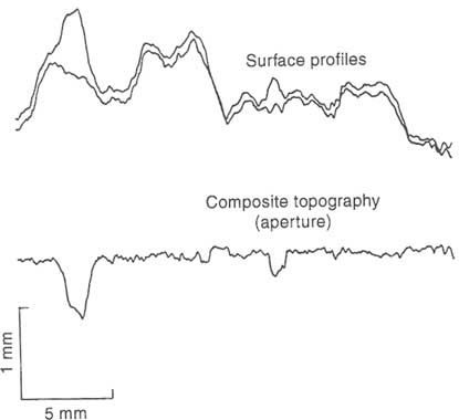
FIGURE 3.1 Example of measured matched profiles and corresponding composite topography. Notice that the high-amplitude long-wavelength components present in the profiles of the individual surfaces are not present in the composite topography. From Brown et al. (1986).
measurements of fracture surface roughness, Roberds et al. (1990) showed that the statistical properties of local apertures can be derived directly from the statistical properties of each of the opposing fracture surfaces. The advantage of methods that use surface roughness data is that such data can be easily obtained. The disadvantages are that changes from nonzero stress conditions must be inferred from models and it may be difficult to match the two halves of the fracture correctly.
In the second category are methods that involve filling the void space with different materials such as epoxy (Gale, 1987; Billaux and Gentier, 1990) or Wood's metal (Pyrak-Nolte et al., 1987a) and other casting techniques (e.g., Hakami and Barton, 1990). Epoxy castings provide good estimates of local aperture geometry, but some techniques require that the sample be sliced and consequently destroyed. Estimates of the areal distribution of void space can be obtained accurately by using Wood's metal, but it is difficult to obtain local aperture geometry. Both local aperture and void distribution can be obtained from other casting methods, but there are problems with resolution.
Although laboratory techniques have shortcomings, a number of insights concerning fracture void geometry have been provided by such measurements. Brown et al. (1986) measured matched profiles from both halves of natural joint surfaces. The power spectrum of local apertures and the composite topography were computed as well. They showed that the local aperture distribution has a power law spectrum at high spatial frequencies (short wavelengths) but flattens out at low spatial frequencies (long wavelengths), as illustrated in Figure 3.2. The crossover between the power law behavior and the flat spectrum allows a mismatch length scale to be defined as the point where the ratio of the local aperture spectrum to the spectrum of the individual surfaces reaches one-half its high-frequency value (Figure 3.2). In the simplest model this mismatch length scale is the third parameter needed to define the roughness of a fracture. This scale is essentially the largest wavelength present in the composite topography with any significant amplitude and defines the dominant roughness component of the fracture.
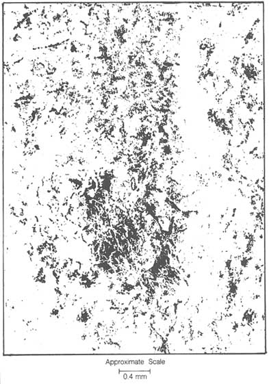
The results of Wood's metal injection tests on two natural granitic fractures subjected to a normal stress of 33 MPa are shown in Figure 3.3. The figure illustrates the inherent heterogeneity in the areal distribution of the void space in natural fractures. Though heterogeneous, it is also clear that the void space is spatially correlated. Nolte et al. (1989) studied the fractal properties of the void geometry of natural granitic fractures, finding that the fractal dimension, D, ranged from about 1.99 to 1.95, depending on the stress level. Further studies (Pyrak-Nolte et al., 1992) suggest that multifractal analyses of fracture void space may distinguish between successive processes that might have altered the fracture void structure.
Measurements (Gale, 1990) of an epoxy cast of a granite fracture indicate that local apertures sizes are lognormally distributed. There is an apparent relationship
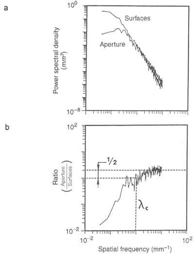
FIGURE 3.2 (a) Power spectra of the surface profiles and aperture (composite topography) shown in Figure 3.1. Notice the lack of power at low frequencies in the aperture relative to the surfaces. (b) Ratio of the aperture spectrum to the surface spectrum. A mismatch length scale ![]() c can be defined by the spatial frequency at which the ratio falls to one-half its high-frequency asymptotic value. For length scales greater than
c can be defined by the spatial frequency at which the ratio falls to one-half its high-frequency asymptotic value. For length scales greater than ![]() c the surfaces are closely matched, and for length scales less than
c the surfaces are closely matched, and for length scales less than ![]() c the surfaces are mismatched. From Brown et al. (1986).
c the surfaces are mismatched. From Brown et al. (1986).
between local aperture size and void extent. That is, large local apertures are associated with laterally extensive voids, whereas small local apertures are associated with restricted voids.
Inferences about the statistical properties of fracture void space have been tested in a number of modeling studies. Several approaches have yielded aperture distributions that visually have properties similar to the experimental results shown in Figure 3.3. Brown (1987), Thompson and Brown (1991), and others have used the fractal properties of surface roughness measurements in combination with the mismatch length scale to generate such patterns. Moreno et al. (1988), Tsang and Tsang (1987), and others have created spatially correlated local aperture patterns, such as those shown in Figure 3.3, by using statistical techniques that assumed lognormal local aperture size distributions. Pyrak-Nolte et al. (1988) used a stratified percolation model to create spatially correlated local aperture patterns that are approximately lognormal. Although lognormal local aperture size distributions are most commonly used in models, analysis of stress/deformation data by Hopkins et al. (1990) indicate that some local aperture distributions may be bimodal.
STRESS EFFECTS ON FRACTURE VOID GEOMETRY
Deformation in a fracture can arise from either a change in fluid pressure or a perturbation of the stress field in the rock. The important stress for mechanical behavior and fluid flow in fractures is the effective stress, which is generally taken to be the normal stress on the fracture minus the fluid pressure (Terzaghi, 1936). In a three-dimensional stress field the normal stress is the component of the total stress measured perpendicular to the fracture plane. By convention in rock mechanics, compressive stresses are taken to be positive in sign, so effective stress values are usually positive. However, in some instances, such as in a hydrofracture, the fluid pressure exceeds the far-field normal stress, so effective stress values are negative.
Under transient conditions, effective stress conditions may be different in fractures and the surrounding porous media. If the matrix permeability is different than the fracture permeability, fluid pressures will be different under transient flow conditions. If matrix permeability is less than the fracture permeability, there will be a larger effective stress in the fracture than in the matrix when fluid is withdrawn. Differences in effective stresses will also arise when the pore compressibility of the rock matrix is greater than the void compressibility of the fractures. In this case, equal reductions in pore and fracture pressures will produce larger effective stress changes in the fracture than in the rock.
When the stress on a fracture changes, it will deform. Because of the importance of fractures to the mechanical behavior of rock masses, a large number of experimental investigations have addressed deformability of fractures. A good summary is presented by Einstein and Dowding (1981). The results of their work
have been incorporated into models of rock mass mechanical behavior (e.g., Roberds and Einstein, 1978). However, the following discussion is restricted to deformability from the standpoint of how it affects the process of fluid flow.
The stress on a fracture can be decomposed into two components, one in a direction perpendicular to the surface (normal) and one in a direction parallel to the surface (shear). In general, the effects of these two components are highly coupled; that is, the deformation caused by a change in one component is dependent on the magnitude of the other. Fracture surface roughness is one of the primary reasons for this coupling, as illustrated in Figure 3.4. This figure shows the distribution of voids and contacting asperities in an idealized representation of a very rough undeformed fracture. The application of shear stress to this fracture at a very low normal stress may cause one surface to ride up and over the asperities of the other, leading to large dilation. At the other extreme, at very high normal stress, the frictional forces resisting slip may exceed the strength of the rock and the asperities will be sheared off. Dilation would be minimal in this case. Deformation associated with these loading conditions is discussed later in this chapter under "Shear Stress Effects." Considerable work, as discussed below, has been carried out for the case in which only changes in effective normal stress are considered. Referring again to Figure 3.4, such studies address closure of voids where the surfaces are not in contact and deformation of asperities where the surfaces are in contact.
Normal Stress Effects
When normal stress is applied to a natural fracture in the laboratory, fracture deformation is typically nonlinear (Figure 3.5). The rate of deformation is greatest at low values of normal stress, indicating that fracture stiffness increases as normal stress increases.
A common feature of fracture deformation is a hysteresis effect during stress loading and unloading, as shown Figure 3.5. In hard clean crystalline rock fractures, hysteresis is almost entirely due to processes arising from mismatch
FIGURE 3.4 Cross section through a very rough fracture in the underformed state showing distribution of voids and contacting asperities.
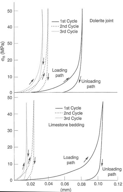
(of opposing fracture surfaces) and sample disturbance. As a mismatched fracture is loaded, slight realignments of the fracture surfaces may occur or asperities may fail. In either case, the geometry of the load-bearing portions of the surface has changed, so the load deformation curve will be different. If a thick fracture infilling is present, or if the fracture is in soft, clay-bearing sediments, inelastic processes also may contribute to the hysteresis effect. After repeated cycling, Pyrak-Nolte et al. (1987a) observed that the nonlinearity of natural fracture deformation persisted without hysteresis, thus leading to the conclusion that deformation is primarily elastic. The degree to which fracture deformation is elastic is important in determining the degree to which fluid flow properties are independent of stress history. If deformation is totally elastic, the fluid flow properties of fractures will be totally dependent on the present stress state.
Elastic nonlinearity arises because as normal stress is applied the geometry of the void space changes as some voids close and additional asperities come into contact. Increased contact area results in stiffening of the fracture. This process is illustrated in Figure 3.6, which shows a Wood's metal cast of the void space in a granite fracture at different stress levels. At low stress levels, there are only a few asperities of contact surrounded by large void areas. As stress is increased, the number of contacting asperities and the contact area increase, but in a nonuniform pattern. Even at moderately high stresses, relatively large areas of void space remain, but they are connected by tortuous channels. These results
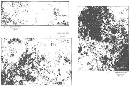
FIGURE 3.6 Composite from micrographs of a portion of a natural fracture at effective stresses of (a) 3 MPa, (b) 33 MPa, and (c) 85 MPa. Void space, filled by Wood's metal, is shown in white; contact areas are black. From Pyrak-Nolte et al. (1987a).
imply that flow must be controlled to a large extent by the location and distribution of flow restrictions or ''critical necks" that connect the larger voids into continuous paths.
As explained in the following paragraphs, at least two approaches have been taken to visualize fracture deformation under normal stress. The first visualizes the fracture as being held open by asperities in contact. As stress is applied, these asperities deform and additional asperities come into contact. The second approach visualizes the fracture as a collection of voids that close as stress is applied. Other approaches have been used for developing models for mechanical deformation of fractures, but these two approaches are the most relevant to fluid flow because they allow changes in stress to be related directly to changes in the geometry of the flow path. It is frequently assumed that the geometry at the point of contact of two asperities can be represented by two touching spheres (a Hertz contact). Solutions exist for both normal and shear loading of Hertz contacts (see Mindlin, 1949; Mindlin and Deresiewicz, 1953; and Timoshenko and Goodier, 1970), from which fracture deformation under both normal and shear loading has been derived (Brown and Scholz, 1985, 1986; Yoshioka and Scholz, 1989a,b). The way in which deformations at each Hertz contact are combined to yield total fracture deformation is important; interactions between contacting asperities are often ignored, leading to underestimates of total fracture deformation.
A fracture may also be visualized as a collection of coplanar flat cracks. Under low stress, the fracture is represented by large, closely spaced cracks that close as stress is applied. As stress increases, cracks with the smallest thickness (out-of-plane dimension) to length (in-plane dimension) ratios close first, and crack spacing increases. Using fracture mechanics, analytical solutions for the deformation of noninteracting as well as interacting cracks are available (e.g., Tada et al., 1973). These solutions have led to important insights into the relationship between fracture deformation or closure measurements and changes in fracture aperture. Pyrak-Nolte et al. (1988) have shown that the volumetric deformation of a rock specimen containing a fracture subjected to stress normal to the fracture plane is equal to the deformation of the intact rock plus the changes in volume of the voids in the fracture. Stated another way, the change in void volume is exactly equal to the volumetric deformation in excess of that which would occur if the fracture were absent. This equivalence arises from conservation of volume. A consequence of volume conservation is that a given volumetric deformation corresponds to a small change in the average value of local apertures if there is a large areal percentage of voids or a large change in average aperture if there is a small areal percentage of voids. Thus, there is not a one-to-one correlation, as is often assumed, between mechanical closure and aperture closure in the fracture.
Hopkins et al. (1990) assumed an asperity model of a fracture but used the Boussinesq solution for deformation of a half-space under a distributed load (Timoshenko and Goodier, 1970) instead of the Hertz contact solution to model
asperity deformation. In this way interaction between asperities was taken into account. They showed that this approach was essentially equivalent to that of the flat-crack model.
Shear Stress Effects
Application of shear stress to a fracture can have a significant impact on void geometry because of the potential for dilation associated with relative motions of the two surfaces. Factors affecting the onset of relative motion and dilation include the magnitude of the normal stress, the roughness of the fracture, and the strength of the matrix and infilling material.
Figure 3.7 illustrates the range in shear behavior of fractures. Curve A shows the shear stress displacement of a clean rough dilatant fracture under constant normal stress. It is characterized by a rapid increase in stress up to a peak, followed by a loss in load-carrying capacity. Curve B, typical of a fracture with a thick infilling, which is usually nondilatant (Papaliangas et al., 1990), shows a more gradual increase in stress with a continuously changing slope.
The dilatancy associated with shear deformation of a fracture is illustrated in Figure 3.8. The lower curve represents the shear deformation behavior under a constant normal stress with shear stress applied in either a positive or negative direction. The upper curve shows the dilation accompanying the shear deforma
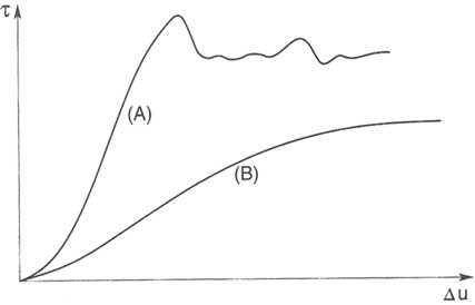
FIGURE 3.7 Curves of shear stress, ![]() , versus shear displacement, u, illustrating the range in shear behavior of fractures under constant normal stress. (A) dilatant behavior; (B) nondilatant behavior. From Goodman (1976).
, versus shear displacement, u, illustrating the range in shear behavior of fractures under constant normal stress. (A) dilatant behavior; (B) nondilatant behavior. From Goodman (1976).
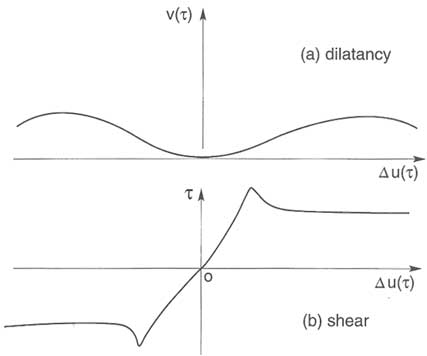
FIGURE 3.8 Illustration of dilatancy, V(![]() ), accompanying shear displacement, u(
), accompanying shear displacement, u(![]() ), of a rough fracture under constant normal stress. From Goodman (1976).
), of a rough fracture under constant normal stress. From Goodman (1976).
tion. For a portion of the stress/deformation curve corresponding to elastic deformation of the fracture, there is minimal dilation. The onset of rapid dilation occurs when asperities begin to slide past one another, causing an increase in aperture. The rate of dilation increases and reaches a maximum value at the peak shear stress (Patton, 1966; Barton, 1973; Barton et al., 1985; Kutter and Otto, 1990). At this point, sufficient asperities fail to permit sliding at a nearly constant shear load. Dilation continues after the peak stress but at an ever-decreasing rate.
Although useful for conceptually describing the coupling between shear and normal stresses, the shearing of dilatant fractures under constant normal stress conditions as depicted schematically in Figures 3.7 and 3.8 usually does not occur in nature. Instead, as the fracture dilates, normal stress increases owing to the stiffness of the surrounding rock mass. Thus, normal stress changes continuously during the shearing process. In the laboratory these conditions are represented by a shear test in which the stiffness normal to the fracture is held constant (e.g., Archambault et al., 1990; Bandis, 1990). For these conditions, Ohnishi and Dharmaratra (1990) observed much lower dilation compared to shear tests under constant normal stress at identical normal stress levels. Ultimately, constitutive models must be able to describe the behavior for all types of boundary conditions.
Measurements of dilation during shear imply that the apertures of voids must be increasing. However, there is very little experimental data to quantitatively characterize these changes in void space. Gale (1990) injected resin into a fracture that was sheared under constant normal stress and found a lognormal distribution of aperture sizes, which is similar to observations of fractures under normal stress. In a numerical model, Wang et al. (1988) imposed a shear displacement on two mirror-image fractal surfaces and developed a quantitative relationship between the power spectrum of the apertures and the relative shear displacement. The mismatch length scale (cf. the earlier section, "Roughness of Fracture Surfaces") tends to increase roughly in proportion to the amount of shear displacement, implying an increase in void apertures with shear displacement.
The two approaches for modeling fracture deformation discussed earlier under "Normal Stress Effects," are not relevant, as currently formulated, to the modeling of shear deformation because neither approach accounts for frictional sliding of asperities or asperity breakage.
Effects of Fracture Origin
As discussed in Chapter 2, the hydrological properties of fracture systems are greatly influenced by their geological origin. The void structure of fractures and the hydraulic properties of the matrix depend on the origin and geological history of the rock. For example, consider two surfaces of a dilating fracture that are almost perfectly matched, with very little void space. Subsequent shearing by tectonic forces and the circulation of fluids will modify the void structure. It would be reasonable to expect that the geometry of the void space will have characteristics that reflect these processes. Void space generated by shearing motions will be affected by the magnitude of normal and shear stresses across the fracture. Shear fractures commonly have slickensides developed on fracture surfaces. In this case the surface roughness may be more highly correlated in one direction, leading to anisotropy in the void structure. Bandis et al. (1981) note that tension joints have the roughest surfaces, that beddingplane surfaces have a range of roughnesses, and that sheared joint and bedding-plane surfaces are often the smoothest.
Geological processes that lead to mineral infilling of the fracture also are important. Hydrothermal processes may alter void space by mineral precipitation or dissolution. Shearing processes can lead to formation of gouge and increasing anisotropy in permeability.
SINGLE-PHASE FLUID FLOW IN FRACTURES
Normal Stress Conditions
Most of the work on fluid flow in single fractures has been carried out under normal stress conditions. Two general techniques have been developed for
measuring the permeability of single fractures in the laboratory: radial flow and linear flow methods. In the radial flow method (Iwai, 1976; Raven and Gale, 1985), a cylindrical sample, which contains a fracture with its plane oriented perpendicular to the axis of the cylinder, is used. A small hole is drilled down the axis of the sample, intersecting the fracture plane. Fluid is injected into the hole at a constant rate, and permeability is determined from the head drop between the hole and the outside of the sample.
The linear flow method (Jones, 1975; Kranz, et al., 1979; Trimmer et al., 1980) utilizes split cylindrical samples in which the axis of the cylinder is contained in the plane of the fracture. The sample is frequently confined in a standard triaxial vessel, and a confining pressure is used to provide the normal stress across the fracture plane. Fluid is injected at one end of the sample, and permeability is determined from the pressure drop along the length of the sample. The quadrant flow method (Pyrak-Nolte et al., 1987a) approximates the flow conditions of the linear flow test. The fracture is oriented with its plane perpendicular to the sample axis, and flow is measured across the sample diameter.
The advantage of the linear flow method is that pressure drops are more uniform over the area of the fracture. Most of the head drop in the radial flow method occurs near the bored hole, so results are affected by heterogeneities in void geometry in this area.
Characteristic flow behaviors of natural fractures as a function of effective stress as observed in the laboratory are illustrated in Figure 3.9. This behavior has been observed in granite rock fractures by Gale (1982) and Raven and Gale (1985), among others, and in sedimentary rock fractures by Jones (1975) and Cook et al. (1990). Figure 3.9 shows a significant hysteresis between loading and unloading curves for the first cycle. This hysteresis is the result of slight mismatches between fracture surfaces, which produce additional pathways for fluid flow. As the load is applied, the surfaces can move slightly relative to each other, becoming better registered, or mated, and removing the effects of the mismatch. Subsequent loading results in much less hysteresis because deformations of the fractures are primarily elastic after the surfaces have become well registered.
Although the deformation of hard clean fractures is elastic, flow experiments on clay-bearing sedimentary rock (Cook et al., 1990) indicate that plastic deformation and creep can occur, causing hysteresis in flow rate measurements. Although no data are available at present, these results imply that soft infilling materials may have similar effects.
Figure 3.9 also shows that the application of normal stress results in a rapid reduction in flow rate. At high levels of normal stress, however, flow rates approach a constant, or irreducible, value. The rapid reduction in flow rate at low stress levels corresponds to closure of voids and a concomitant increase in tortuosity (see micrographs in Figure 3.6 and further discussion later, under "Relationship Between Hydraulic and Electrical Properties"). The increase in
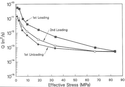
tortuosity occurs in a heterogeneous fashion, leading to development of restrictions or "necks" between larger voids. At the highest stress levels, all flow must pass through one or more "critical necks." These restrictions are more equant in shape than the surrounding voids. Thus, the flow rate approaches a value independent of stress at high stress levels but may be orders of magnitude lower than at low stress. This has been referred to as irreducible flow (Pyrak-Nolte et al., 1987a). Mechanical closure continues at high stress levels because the large voids separated by the restrictions continue to deform.
The most common model for flow in a single fracture is the "cubic law," in which the fracture is represented by two parallel plates separated by a constant distance. The equation for one-dimensional flow between two parallel plates is
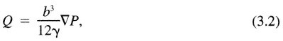
where Q is the volumetric flow rate per unit width (measured in the plane of the plate), b is the distance between the plates, ![]() P is the pressure gradient, and
P is the pressure gradient, and ![]() is the dynamic viscosity. This equation has long been used to model macroscopic fracture flow. Recently, researchers have applied the law at a microscopic level, where the distance between fracture walls, the local aperture, is prescribed at each point in the fracture (e.g., Brown, 1987; Tsang, 1984; Thompson and Brown, 1991; see also "Relationship Between Hydraulic and Electrical Properties" later
is the dynamic viscosity. This equation has long been used to model macroscopic fracture flow. Recently, researchers have applied the law at a microscopic level, where the distance between fracture walls, the local aperture, is prescribed at each point in the fracture (e.g., Brown, 1987; Tsang, 1984; Thompson and Brown, 1991; see also "Relationship Between Hydraulic and Electrical Properties" later
in this chapter). The success of these models in simulating various aspects of the flow behavior observed at macroscopic scales indicates that the cubic law correctly relates local aperture and flux under laminar flow conditions and implies that, for laminar flow in fractures, viscous drag is the primary mechanism for head loss under constant flux conditions. Studies by Pyrak-Nolte et al. (1988) and Yang et al. (1989) also have shown that the geometric shapes of the local voids do not have a significant effect on flow rate. Elliptical voids and parallel-plate geometrics yield similar results. A robust analysis of the assumptions used in applying the cubic law at the local level would require complete solution of the Navier-Stokes equations in a realistic fracture void geometry.
The difficulty in applying the cubic law in the macroscopic sense (i.e., to predicting flow in a real fracture with rough walls) is in defining a representative distance between the fracture walls. Fracture openings in the field or from a core are commonly measured by using an automotive "feeler gauge." These are more nearly local aperture measurements rather than a representative distance between the fracture surfaces. In the laboratory the distance between fracture walls is often taken to be the measured mechanical closure relative to a maximum closure, under a load applied normal to the fracture surface. (Maximum closure is defined as the closure beyond which there is no deformation in excess of that in the intact rock.) This measurement is called the mechanical aperture. Another measure of the distance between the fracture walls can be obtained by measuring Q and ![]() P and then applying Eq. 3.2 to obtain b, the hydraulic aperture. In general, the mechanical aperture and the hydraulic aperture will not be equal.
P and then applying Eq. 3.2 to obtain b, the hydraulic aperture. In general, the mechanical aperture and the hydraulic aperture will not be equal.
Figure 3.10 shows experimental flow rate measurements from a single fracture in claystone. The measurements were carried out over a range of conditions when the fracture was propped open with shims and with the fracture surfaces in contact and under moderate stress. The figure shows that experimental flow rate is close but not quite equal to the predicted flow rate even when the fracture is propped open. As the fracture is closed, deviation of the experimental data from the cubic law increases rapidly. Fracture permeability decreases more rapidly than predicted by the cubic law in which the variable b was assigned the value of mechanical apertures as defined above. Similar behavior has been observed in other studies (Raven and Gale, 1985; Pyrak-Nolte et al., 1987a; Gale, 1990).
For completely open fractures (fracture surfaces not in contact), analysis of data such as those presented in Figure 3.10 shows that the cubic law is valid when corrected by a friction factor, f, to account for the roughness of the fracture surfaces, that is, when Eq. 3.2 becomes (Witherspoon et al., 1980)
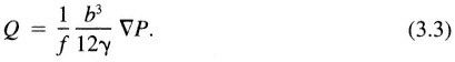
Cook et al. (1990) showed that the friction factor could be expressed in terms of an increase in the tortuosity of the flow path in the fracture.
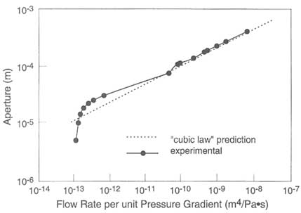
FIGURE 3.10 Flow rate through a fracture in claystone as a function of mechanical aperture (solid curve) and hydraulic aperture (broken curve) predicted by substituting the mechanical aperture into b in Eq. (3.2) and solving for Q/ΔP. From Cook et al. (1990).
In some applications, such as hydrofracturing, in which negative effective stresses are common and the fracture surfaces are separated, the parallel-plate approximation (Eq. 3.2) is appropriate. For such cases, aperture is proportional to the effective stress, assuming the matrix behaves elastically. The proportionality constant can be expressed in terms of the fracture stiffness, which in turn is a function of the fracture dimensions. As a first-order approximation, a hydrofracture can be represented by a two-dimensional flat elliptical crack of length 2c (Figure 3.11). In this representation the axis of the injection well would be perpendicular to the page and located at the center of the crack. The relationship between the effective stress and the value of b at the crack centerline (bmax) is (Snedden and Elliot, 1946)
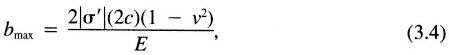
where ![]() ' is the effective stress, v is the Poisson's ratio, and E is Young's modulus.
' is the effective stress, v is the Poisson's ratio, and E is Young's modulus.
Lamb (1932) showed that the pressure gradient required for a particular rate of flow in an elliptical conduit of essentially zero eccentricity is 16/3 π times as great as the flow between parallel plates, all other conditions being equal. Combining Eq. 3.4 with Eq. 3.2 and multiplying by this factor gives the relationship for
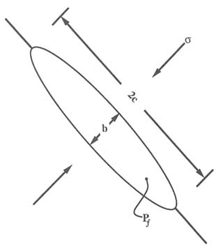
FIGURE 3.11 Deformation of a single flat two-dimensional crack with internal pore pressure Pf.
flow in a flat elliptical crack: In this case the flow rate, Q, can be directly related to the effective stress.

When the two sides of a fracture are brought into contact under normal stress, deviations from the cubic law in which b is taken as the mechanical aperture (Figure 3.10) arise because in-plane tortuosity increases and the contact area changes. The effect of increasing in-plane tortuosity has been evaluated by Walsh (1981) using an analogy with heat conduction. He derived a correction factor, (1 - d)/(1 + d) as a multiplier on the right-hand side of Eq. 3.3. In this factor, d is the ratio of the contact area of asperities to the total fracture area at a given normal stress. The value of the factor decreases as the contact area increases, causing a reduction in permeability. Tsang (1984) and Brown (1987) also showed that tortuosity results in a decreased flow, with the magnitude of the effect depending on the distribution and correlation of local apertures. (See also "Relationship Between Hydraulic and Electrical Properties" later in this chapter.)
The increase in contact area with increasing normal stress causes the mean value of local aperture to decrease more rapidly than the measured mechanical aperture. This is due to the conservation of volume during elastic deformation, as discussed previously. At high stress levels, when critical necks begin to form, all flow must pass through the relatively small number of equant-shaped necks along the connected flow path. While dominating the flow, these equant-shaped necks contribute little to the total void volume change. Voids disconnected from the flow path continue to deform, leading to continued mechanical aperture changes, but flow becomes insensitive to further stress changes.
Yang et al. (1989) incorporated the conservation of volume constraint into a network model of flow in a fracture where the initial void space distribution was created by a statistical technique known as stratified percolation (Pyrak-Nolte et al., 1988). They showed that flow rate decreased more rapidly than predicted by the cubic law and suggested that a large percentage of the head drop in a fracture occurred at the critical neck along the path of the largest connected local apertures.
Cook et al. (1990) incorporated both the effects of tortuosity and conservation of void volume into a modified cubic law given by
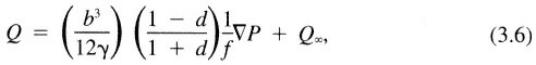
where b equals b0 - (bm + ![]() ), b0 is the maximum fracture closure, bm is the mechanical closure in response to applied normal stress,
), b0 is the maximum fracture closure, bm is the mechanical closure in response to applied normal stress, ![]() represents additional change in aperture to ensure conservation of volume, and Q∞ is irreducible flow.
represents additional change in aperture to ensure conservation of volume, and Q∞ is irreducible flow.
In this equation, f accounts for the out-of-plane tortuosity and is significant only when the fracture planes are not in contact. The factor (1 - d)/(1 + d), as discussed above, accounts for in-plane tortuosity. Using Eq. 3.6 and a highly idealized model to calculate void volume change, Cook et al. (1990) were able to obtain a good fit of experimental data over a range of conditions. They evaluated ![]() ∞ at a constant-head difference. In general, its value is a function of both the viscosity of the fluid and the applied head, and this would be included in terms of Eq. 3.6 modified by
∞ at a constant-head difference. In general, its value is a function of both the viscosity of the fluid and the applied head, and this would be included in terms of Eq. 3.6 modified by ![]() P.
P.
Shear Stress Conditions
As described earlier, application of shear stress can significantly alter the void space, and hence the flow, in a fracture. When dilation occurs, increases in permeability of one to two orders of magnitude have been observed (Makurat, 1985; Gale, 1990; Esaki et al., 1991). Barton et al. (1985) established empirical relationships between fracture surface roughness, mechanical properties of the wall rock, and permeability under shear stress. They showed that, under normal stresses high enough to cause asperity failure during shear, permeability may
actually decrease. Olsson (1992) ascribed the observed decreases in permeability to the formation of gouge material. He also found that the decrease was greater for rough fractures. Detailed studies of the relationship between flow and void structure under combined normal and shear stresses are not well advanced. Such studies are important for understanding flow in systems where the activities of humans result in large differences in principal stress magnitudes. Such conditions are likely to occur in civil and mining works such as underground openings, dams, and slopes where the principal stress at the free surface is zero.
Thermal and Chemical Effects
A brief discussion of the thermal and chemical effects on fluid flow in a single fracture is given here. A more complete discussion of this topic can be found in Chapter 7.
Changes in temperature may change the effective stress state in the rock mass. These stress changes may cause fractures to deform, affecting flow, as described in previous sections. It should be noted that the primary effects are actually due to thermal gradients, not temperature. Whereas a uniform temperature increase under displacement-free boundary conditions is known to affect the permeability of some intact rocks (e.g., Heard and Page, 1982), this is considered to be a second-order effect in fractures. If temperature is raised in a nearly vertical fracture intersected by a vertical borehole, the fracture will close owing to the increased hoop stress. This phenomenon has been observed in the field (Nelson et al., 1981) and has been modeled (Noorishad et al., 1984). A tunnel would be expected to experience similar effects.
Various chemical processes would be expected to have significant effects on flow in fractures, although there are few available data specific to fractures. Precipitation or dissolution would be expected to decrease or increase permeability, respectively (see Appendix 2.A). Gale and Reardon (1984) studied the precipitation of calcite along connected flow channels and observed reductions in laboratory measurements of flow in a single fracture.
The presence of clays as fracture linings could affect flow in several ways. First, as discussed previously, the mechanical deformability of the fracture may be changed (usually increased). Second, under some chemical conditions, the clays will migrate, causing significant reduction of permeability by plugging pore throats. This phenomenon has been demonstrated in porous media (Khilar and Folger, 1984) and could occur in fractures. Third, some clays are susceptible to volume change in the presence of liquids. The amount of change depends on a number of factors, including clay mineralogy, fluid chemistry, and the degree of confinement provided by the surrounding rock. Carter (1990) showed that the volumetric expansion of Na-montmorillonite clays in response to reductions in water salinity can dramatically decrease fracture permeability. These decreases, however, were observed at salinity levels much higher than anticipated based on
the traditional description of clay-particle interactions provided by the Gouy-Chapman double-layer theory (Mitchell, 1993). Results such as these illustrate the large number of questions that still remain about the effects of clay-fluid interactions on permeability.
Finally, pressure solution can affect flow, particularly at elevated temperatures. In a fracture, pressure solution may arise from stress concentrations at points of contact between asperities, and dissolved constituents will move to locations of lower stress where precipitation occurs. This process could affect flow by filling void space. Perhaps more importantly, it could also change the stiffness of the fracture. Effects of pressure solution on compaction of quartz aggregates have been studied experimentally (Sprunt and Nur, 1977), but, to the committee's knowledge, no data exist for fractures. The actual mechanism for pressure solution remains unclear, although theories have been presented by Rutter (1983), Lehner and Bataille (1984), and others.
SOLUTE TRANSPORT
Solute transport depends strongly on the distribution of velocities in the fracture. The residence time of solutes will be affected by the distribution of void sizes along connected flow paths and, of course, the path lengths. Although flow rate is dominated by the size and number of critical necks, the residence time is strongly influenced by the larger voids along the path. Consequently, the residence time could be longer than that calculated with a parallel-plate model even if the hydraulic aperture assumed in the model were obtained from flow measurements. Numerical model studies by Thompson and Brown (1991) indicate that tracer velocities may be less or greater than the average fluid velocity depending on fracture roughness and contact area. (See also ''Relationship Between Hydraulic and Electrical Properties" later in this chapter.) Specifically, they found that if the fracture surfaces are rougher in one direction, the tracer velocity is less than the average fluid velocity if flow is transverse to the roughness and greater if flow is parallel to the roughness.
Variations in aperture size also may affect the dispersion of solutes in fractures. Tsang and Tsang (1987) and Tsang et al. (1988) developed a one-dimensional variable-aperture model for transport. Their numerical results showed that variations in aperture size can lead to the formation of "fast" and "slow" paths that are apparent from tracer breakthrough (or travel time) curves. These models assume that the apertures vary in a spatially correlated manner along the lengths of the channels and that their widths are constant. The effects of large volumes of fluid contained in voids of large areal extent along the flow path (e.g., Figure 3.6) are not, however, taken into account in the model.
Dispersion also is affected by the tortuosity and connectivity of multiple-flow paths. In a model in which apertures were correlated and lognormally distributed, Moreno et al. (1988) found that dispersivity (![]() ), as reflected in the
), as reflected in the
Peclet number (![]() /L, where L is travel distance), was most strongly dependent on variance of the aperture distribution. Models by Smith et al. (1987) predict that the effects of connectivity and tortuosity could lead to major differences in the values of effective apertures derived from flow and tracer measurements. Such discrepancies have been observed in laboratory tests performed by Gale (1990) and Piggot and Elsworth (1990).
/L, where L is travel distance), was most strongly dependent on variance of the aperture distribution. Models by Smith et al. (1987) predict that the effects of connectivity and tortuosity could lead to major differences in the values of effective apertures derived from flow and tracer measurements. Such discrepancies have been observed in laboratory tests performed by Gale (1990) and Piggot and Elsworth (1990).
Piggot and Elsworth (1990) also performed tracer tests on fractures in a sheared condition. Although the fracture void volume was greater, the shape of the breakthrough curve was very similar to that obtained with the fracture in the mated condition.
Additional work is needed to more quantitatively relate geometrical properties of the void space to transport properties. It is worth reemphasizing that the limited available data show a lack of correlation between effective apertures based on hydraulic flow and transport measurements.
TWO-PHASE IMMISCIBLE FLUID FLOW
In single-phase flow, fracture geometry at the aperture scale determines flow and transport characteristics. Under two-phase immiscible fluid flow conditions, phase geometry (i.e., the geometry that is saturated with each phase) in the fracture ultimately controls the permeability to each phase, fluid pressure/saturation relationships, and solute dispersion in each phase. Phase geometry in the fracture also influences flow and transport through the surrounding porous matrix blocks by affecting hydraulic contact between the blocks. Although two-phase flow in porous media has received much attention, study of two-phase flow in fractures has only recently begun. Pressure/saturation and permeability/saturation relationships have been explored numerically and, more recently, measured in transparent rough-walled fracture analogs where phase geometry can be observed. The major difference between two-phase immiscible flow in porous media and in fractures is the two-dimensional nature of the aperture network. This increases the importance of phase interference and trapping phenomena, as discussed below.
Static and Quasi-Static Conditions
Under static conditions, viscous forces do not influence phase pressure. Therefore, assuming thermodynamic equilibrium, phase geometry in a horizontal fracture will be controlled entirely by capillary forces. The nonwetting fluid will be found in large apertures and the wetting fluid in small ones. The Laplace-Young equation (e.g., Adamson, 1990) relating the surface tension, T, to the pressure jump, ![]() P, across the curved fluid-fluid interface
P, across the curved fluid-fluid interface ![]() P dictates which phase is present at a particular location as a function of phase pressure:
P dictates which phase is present at a particular location as a function of phase pressure:
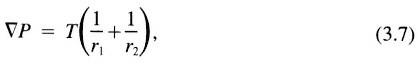
where r1 and r2 are the two principal radii of curvature. For a fracture the first principal radius of curvature, r1, is taken normal to the plane of the fracture and is equal to b/(2cos ![]() ), where b is the local aperture and
), where b is the local aperture and ![]() is the fluid/fluid/rock contact angle. Local in-plane curvature, r2, is assumed not to contact the rock surface and therefore is not constrained by a contact angle. In a random aperture field, assuming that curvature in the plane of the fracture is negligible and that the distribution of phases is not inhibited by lack of accessibility will lead to phase structure/pressure relationships conforming to a percolation process on a two-dimensional network, as introduced by Broadbent and Hammersley (1957). A variety of interesting results come from percolation theory, the most important being that the phase geometry is fractal and that a critical pressure exists where one phase forms an infinite connected cluster isolating the other phase (see Chapter 7 in Feder, 1988).
is the fluid/fluid/rock contact angle. Local in-plane curvature, r2, is assumed not to contact the rock surface and therefore is not constrained by a contact angle. In a random aperture field, assuming that curvature in the plane of the fracture is negligible and that the distribution of phases is not inhibited by lack of accessibility will lead to phase structure/pressure relationships conforming to a percolation process on a two-dimensional network, as introduced by Broadbent and Hammersley (1957). A variety of interesting results come from percolation theory, the most important being that the phase geometry is fractal and that a critical pressure exists where one phase forms an infinite connected cluster isolating the other phase (see Chapter 7 in Feder, 1988).
Numerical simulation of the percolation process on spatially correlated aperture networks has been used to evaluate phase structure as a function of pressure. Subsequent modeling of flow through each phase structure allows estimation of relative permeability as a function of pressure (Pruess and Tsang, 1990; Pyrak-Nolte et al., 1990a). These calculations indicate significant phase interference. That is, the sum of the wetting and nonwetting phase-relative permeabilities is considerably less than 1 (see Figure 3.12). Results of percolation theory on a random network also show that anisotropy in the correlation lengths (i.e., distances
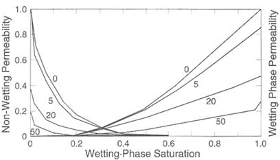
FIGURE 3.12 Effect of stress on relative permeabilities for a reduction in aperture of 5, 20, and 50 units of aperture. The saturation at which the nonwetting and wetting phase curves cross varies only a small amount with stress. From Pyrak-Nolte et al. (1990a).
over which similar values of a parameter are likely to be found) is required for the existence of two-phase mobility. This is because anisotropy can lead to the formation of parallel-connected phases. The validity of such methods for calculating two-phase fracture properties depends on the assumption that thermodynamic equilibrium predetermines phase structure for a given pressure and aperture structure. Equilibrium requires all apertures to be in a state of mutual communication. Three communication processes exist: (1) flow through the matrix that connects all apertures, (2) film flow along the fracture walls, and (3) diffusional processes. Recent experiments on a transparent cast of a natural fracture show that the interference between two phases flowing simultaneously in a fracture can be strong. At intermediate saturations, the sum of wetting and nonwetting phase-relative permeabilities was found to be much less than 1, supporting the results of numerical simulation (Persoff et al., 1991).
For a large number of situations, either communication processes do not exist or phase displacement occurs rapidly with respect to the communication processes. For these situations, accessibility of apertures to a phase (i.e., the proximity of an aperture to a phase and connection in the phase to a source or sink), places an additional control on phase geometry. If the displacement process is sufficiently slow that viscous forces can be neglected relative to capillary forces, accessibility rules may be combined with Eq. 3.7 to dictate the development of phase structure under quasi-static conditions.
Numerical models that incorporate the phase accessibility rule with Eq. 3.7, neglecting in-plane curvature, can be formulated; they conform to the process of invasion percolation introduced by Wilkinson and Willemsen (1983). Figure 3.13a shows the phase structure at breakthrough as water (the wetting fluid) supplied at the narrow boundary displaces air (the nonwetting fluid) under quasistatic conditions in a horizontal transparent rough-walled analog fracture. An example of a phase structure as simulated by the invasion percolation process on the measured aperture field for the experiment depicted in Figure 3.13a is shown in Figure 3.13b. The simulation predicts the phase structure to be much more complicated than what actually develops. Modification of the model to include in-plane curvature (r2 in Eq. 3.7) in the calculation of aperture-phase entry pressure yields a phase structure (Figure 3.13c) comparable to those observed experimentally (Glass, 1993).
Processes by which a phase enters the fracture, including invasion from one edge of the fracture as discussed above, entry from the surrounding porous media, and entry through partitioning from the other phase, will significantly affect phase structure. As an example, Figure 3.14 shows the phase saturation structure in an air/water system in a horizontal analog fracture formed by a flat porous matrix in close contact with a roughened glass plate. Saturation/pressure relationships measured on this analog fracture/matrix system show strong hysteresis between wetting and drainage curves; nonwetting-phase entrapment reduced final wetting-phase saturation to approximately 60 percent (Glass and Norton, 1992).
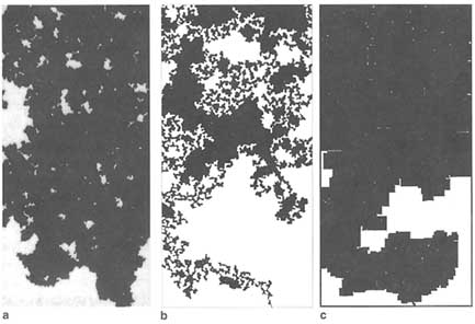
FIGURE 3.13 Phase structure at breakthrough in a rough-walled analog fracture with water (the wetting fluid, black) entry along the short side of the fracture (figure top) and air (white) exits along the other three sides of the fracture. Parts (a), (b), and (c) depict an experiment, a simulation using invasion percolation, and a simulation using a modified invasion percolation model, respectively. Simulations in parts b and c were carried out on the measured aperture field for the experiment a quarter of the size of that shown in part a. Gray areas in the simulation depict entrapped air phase. From Glass (1993).
For fractures that are nonhorizontal, gravity combines with capillarity under quasi-static conditions to dictate the sequence of fracture apertures that fill with the displacing phase. When the denser fluid underlies the lighter one, which is infiltrating from above, gravity tends to flatten the interface as displacement proceeds. However, if the more dense fluid is above the less dense fluid, gravity destabilizes the interface, resulting in the formation of gravity-driven fingers, even under quasi-static conditions. Experiments and simulations of gravity-driven fingering in the quasi-static limit show that the fingers widen and meander/branch as the inclination of the fracture with respect to the vertical decreases (Glass, 1993; Nicholl et al., 1993b). The opposite holds for fluids infiltrating from below. For example, air moving up into water-filled fractures will finger.
Dynamic Conditions
In situations where viscous forces are important, they combine with capillary, gravitational, and inertial forces (for large Reynolds numbers) to yield phase structure. In general, determination of the phase structure requires that the Navier-
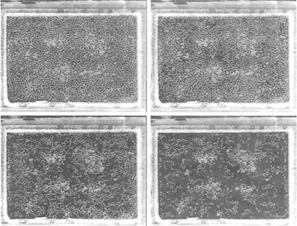
FIGURE 3.14 Growth of phase structure as a function of increasing liquid pressure (sequence is upper left, upper right, lower left, lower right) in an analog fracture/matrix system. Water (the wetting phase, black) enters the fracture from the saturated matrix. Air (the nonwetting phase, white) exits the fracture around the fracture edges. Courtesy of R. J. Glass.
Stokes equations for each fluid be solved with boundary conditions at the moving fluid/fluid interface incorporating a dynamic contact angle (Dussan, 1979; de Gennes, 1985). Although solution approaches based on cellular automata are under development (e.g., Stockman et al., 1990), this is still an intractable problem. Approaches that include accessibility rules and first-order viscous forces in the form of a modified invasion percolation model have been applied to porous networks and may be useful for fractures. Phase structures, however, may not be stable, and a variety of phenomena can occur, including viscous and gravity-driven fingering, flow pulsation, and blob flow (i.e., when one phase moves through another phase as a disconnected unit).
Viscous and gravity-driven fingering have been studied in smooth-walled fractures (Hele-Shaw cells) as an analog for two-phase flow in porous media. Linear stability analysis of the problem shows three factors to be influential in determining interfacial stability during a steady one-dimensional vertical downward displacement of one fluid (indicated by the subscript 2 below) by another (indicated by the subscript 1 below) in a smooth-walled fracture of aperture b:
(1) the fluid viscosity difference (![]() 1 -
1 - ![]() 2), (2) the fluid density difference (p1 - p2), and (3) the interfacial velocity (U) (Saffman and Taylor, 1958; Chouke et al., 1959). This result suggests instability for all wavelengths when the inequality
2), (2) the fluid density difference (p1 - p2), and (3) the interfacial velocity (U) (Saffman and Taylor, 1958; Chouke et al., 1959). This result suggests instability for all wavelengths when the inequality
is satisfied, where g is the gravitational acceleration and ![]() is the fracture inclination with respect to the gravity vector. Although several assumptions have been made to derive this equation (e.g., that the fracture is smooth walled, fluids are incompressible, disturbances are infinitesimal, and capillary forces are negligible), the relationship between buoyant and viscous forces is instructive. Flows are seen to be either stabilized or destabilized by viscosity and density differences with the interfacial velocity modifying the viscosity difference. The role of capillarity at the interface has not been included in the derivation of Eq. 3.8; however, when it is included, it limits the unstable wavelengths to be above a minimum value. Most research has concentrated on viscous-driven fingering in smooth-walled fractures in the absence of gravity (see reviews by Saffman, 1986, and Homsy, 1987). Gravity-driven fingering has been studied recently in rough-walled analog fractures for air/water systems (Nicholl et al., 1992, 1993a,b; see Appendix 3.B).
is the fracture inclination with respect to the gravity vector. Although several assumptions have been made to derive this equation (e.g., that the fracture is smooth walled, fluids are incompressible, disturbances are infinitesimal, and capillary forces are negligible), the relationship between buoyant and viscous forces is instructive. Flows are seen to be either stabilized or destabilized by viscosity and density differences with the interfacial velocity modifying the viscosity difference. The role of capillarity at the interface has not been included in the derivation of Eq. 3.8; however, when it is included, it limits the unstable wavelengths to be above a minimum value. Most research has concentrated on viscous-driven fingering in smooth-walled fractures in the absence of gravity (see reviews by Saffman, 1986, and Homsy, 1987). Gravity-driven fingering has been studied recently in rough-walled analog fractures for air/water systems (Nicholl et al., 1992, 1993a,b; see Appendix 3.B).
Flow pulsation and/or blob flow has been noted in several experiments in transparent analog fractures. Pulsation was observed to be a function of flow rate during relative permeability experiments (Persoff et al., 1991). Flow pulsation and blob flow also have been documented to occur as flow rate through a stable gravity-driven finger is reduced (Nicholl et al., 1993b). In both of these situations, local interactions of the wetting and nonwetting fluids yield system dynamics that have the potential to be chaotic (see Appendixes 3.B and 3.C).
SEISMIC PROPERTIES
The two properties that characterize seismic wave propagation in all media are velocity and attenuation. Velocity is a function of the elastic moduli and density of the medium. Attenuation is a measure of the energy lost from the wave as it propagates. In general, fractures cause a decrease of the modulus of elasticity of the rock and hence a reduction in seismic velocity. They also cause energy loss, leading to increased attenuation. The physical processes governing both effects are discussed in the following sections. In most applications the seismic wavelength is large compared to fracture size (areal extent) and spacing, so the effects of individual fractures are embedded in parameters describing the bulk material behavior. These effective media models are discussed in the next section. More recently, the effects of individual fractures have been modeled explicitly, as discussed later in this chapter under "Discrete Fracture Effects."
Effective Media Models
Velocity
Fractures affect the elasticity (modulus) of a rock because of the discontinuity of local elastic displacements across the fracture face. This discontinuity affects the propagation of seismic waves according to the ratio of fracture size to the seismic wavelength. Considering that any seismic pulse consists of a spectrum of wavelengths, a single fracture will act as a discrete scatterer for those wavelengths that are longer or comparable in size. The resulting radiation pattern depends on the orientation of the fracture with respect to the incident wave. Such scattering effects are common in the sonic frequency band used in acoustic logging.
More commonly (in the seismic context), fractures are small compared to seismic wavelengths; in the limit, many small scatterers are equivalent to an effective medium with decreased velocity and increased attenuation. If the fractures have a preferred orientation, the effective medium is anisotropic.
The physics of fracture-wave interaction is well understood in principle, but the complexity of natural geometries imposes the need for simplifying assumptions. A number of different approximations, utilizing different levels of phenomenology and geometric idealization, are available, as discussed below.
At the most phenomenological level, Schoenberg and Muir (1989) have presented a calculus for constructing a rock by linear combinations of grains, pores, and cracks of known compliance (normal and tangential). This formalism sidesteps all the physics connecting effective compliance to fracture geometry as well as all nonlinearities and rock-fluid mechanical interactions.
If the crack shapes are idealized as very thin oblate ellipsoids, the modulus of the rock and hence the seismic velocities are calculable in terms of aspect ratios (thickness/length) of the ellipsoids and the elastic properties of the surrounding matrix and fluids (see Budiansky and O'Connell, 1980, and references cited therein). If the crack density is small, the decrease in the modulus also is small and is well understood in terms of the properties of the matrix, the fluid, and the crack geometry. If the crack density is large, the corresponding modulus decrease is large. However, there is no consensus about how to treat the nonlinearity arising from large densities. Any theoretical treatment must be consistent with the classic work of Biot (1956) if it shares the same assumptions, such as a locally uniform value for the perturbation in pore pressure caused by the elastic wave (Thomsen, 1985).
If the thin and flat cracks are isolated from the equant pore space, the modulus decrease depends also on the crack aspect ratio and crack density (Hudson, 1980). The presence of liquid (rather than gas) in the cracks considerably stiffens them for P-wave propagation. However, if the cracks are hydraulically connected to the equant pore space, the liquid may squirt from crack to pore, reducing the stiffening effect (Thomsen, 1991). This mechanism and its effects on modulus were recently confirmed in experiments conducted by Rathore et al. (1991).
Attenuation
Heterogeneity causes scattering, which results in attenuation and dispersion. Fluid-filled fractures have several attenuation mechanisms that arise because of the viscosity of the fluid (Budiansky and O'Connell, 1980). At the highest (megahertz) frequencies, energy losses caused by laminar flow dominate. At ultrasonic to sonic frequencies, energy loss caused by fluid motion from cracks to pores ("squirt flow") dominates, depending on a characteristic frequency, fs, given by
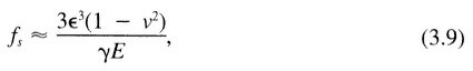
where ∈ is the crack aspect ratio (thickness/length; Budiansky and O'Connell, 1980). For brine in sandstone, with ∈ in the range of 0.01 to 0.001, fS is 103 to 106 Hz. However, high-viscosity fluids (e.g., hydrocarbons) can lower fs into the seismic range (Jones, 1986). While this particular equation shows that seismic attenuation is strongly dependent on the crack aspect ratio, it implies, more generally, that attenuation is strongly dependent on fracture microgeometry.
At seismic frequencies in brine-filled rock, local flow may equalize the fluid pressure locally, and the predominant mechanism of attenuation may be global flow, as identified by Biot (1956).
Discrete Fracture Effects
It is generally accepted that one of the most important developments in seismic geophysics is improved structure resolution. There is, therefore, an emphasis on the development of high-frequency sources, particularly for cross-well or reverse (borehole to surface) vertical seismic profiling applications. Wave propagation in this case cannot be adequately represented by effective media models because the planar extent of fractures, as well as their spacing, is large or comparable to the wavelength of the propagating wave. The effects of each discrete fracture must be evaluated.
As described in the first section of this chapter, a fracture can be envisioned as a collection of voids separated by contacting asperities, all lying in a plane. Each of these voids is a scatterer, as discussed in the previous section. However, as long as the wavelength of the propagating wave is long compared to the spacing of the voids, an areal average value of the discontinuity in elastic displacements occurring at the voids can be assumed in calculations of the far-field reflected and transmitted wave fields. Such an approach is called a seismic displacement discontinuity model. Because the average displacement discontinuity is equal to the ratio of the applied stress and the mechanical stiffness of the fracture, the boundary conditions for reflection and refraction of a plane wave incident on the
fracture can be written as
where u refers to particle displacements, ![]() is the time-varying seismic stress,
is the time-varying seismic stress, ![]() is the stiffness of the fracture, and the subscripts I and II refer to the media on either side of the fracture. Eq. 3.10 shows that displacements are discontinuous across a fracture by the amount
is the stiffness of the fracture, and the subscripts I and II refer to the media on either side of the fracture. Eq. 3.10 shows that displacements are discontinuous across a fracture by the amount ![]() /
/![]() , whereas stresses are continuous. Using the boundary conditions given in Eq. 3.10, solutions for obliquely incident waves and for materials with different properties on each side of a fracture have been obtained (Schoenberg, 1980; Pyrak-Nolte et al., 1990b). The effects of multiple fractures have been modeled by Schoenberg (1983) and Pyrak-Nolte et al. (1990c). The displacement and discontinuity model predicts from a single set of assumptions that a fracture will cause a group time delay and a loss in amplitude of the transmitted wave, the magnitude of which depends on the frequency and on the ratio of fracture stiffness to the seismic impedance of the intact rock. (The term "group" refers to an energy-carrying packet of frequencies in the propagating wave. The group time is what is normally used in laboratory and field measurements to compute the seismic wave velocity.) The group time delay can be used to calculate an effective group velocity that also is time dependent (Pyrak-Nolte et al., 1987b). General characteristics of the theory are illustrated by Figure 3.15, which shows the theoretical magnitudes of the transmission and reflection coefficients and normalized group time delay for a seismic wave normally incident on a single fracture. The value ¦R¦, the coefficient of reflection, increases, while the value ¦T¦, the coefficient of transmission, decreases, owing to conservation of energy. The figure also shows that ¦T¦ is a maximum at zero frequency, where ¦R¦ is a minimum. The normalized group time delay is a maximum at zero frequency and decreases with increasing frequency. As stiffness approaches infinity, the displacement discontinuity becomes equivalent to a welded interface, and all the energy is transmitted. If the stiffness tends to zero, the displacement discontinuity reverts to the case of a free surface, and all the energy is reflected.
, whereas stresses are continuous. Using the boundary conditions given in Eq. 3.10, solutions for obliquely incident waves and for materials with different properties on each side of a fracture have been obtained (Schoenberg, 1980; Pyrak-Nolte et al., 1990b). The effects of multiple fractures have been modeled by Schoenberg (1983) and Pyrak-Nolte et al. (1990c). The displacement and discontinuity model predicts from a single set of assumptions that a fracture will cause a group time delay and a loss in amplitude of the transmitted wave, the magnitude of which depends on the frequency and on the ratio of fracture stiffness to the seismic impedance of the intact rock. (The term "group" refers to an energy-carrying packet of frequencies in the propagating wave. The group time is what is normally used in laboratory and field measurements to compute the seismic wave velocity.) The group time delay can be used to calculate an effective group velocity that also is time dependent (Pyrak-Nolte et al., 1987b). General characteristics of the theory are illustrated by Figure 3.15, which shows the theoretical magnitudes of the transmission and reflection coefficients and normalized group time delay for a seismic wave normally incident on a single fracture. The value ¦R¦, the coefficient of reflection, increases, while the value ¦T¦, the coefficient of transmission, decreases, owing to conservation of energy. The figure also shows that ¦T¦ is a maximum at zero frequency, where ¦R¦ is a minimum. The normalized group time delay is a maximum at zero frequency and decreases with increasing frequency. As stiffness approaches infinity, the displacement discontinuity becomes equivalent to a welded interface, and all the energy is transmitted. If the stiffness tends to zero, the displacement discontinuity reverts to the case of a free surface, and all the energy is reflected.
Fracture stiffness, ![]() , is defined as
, is defined as
where ![]() is the areal average displacement in the plane of the fracture. The relationships between displacement in a fracture and the void geometry are discussed in detail later in this chapter under "Stress Effects on Fracture Void Geometry." Conceptually,
is the areal average displacement in the plane of the fracture. The relationships between displacement in a fracture and the void geometry are discussed in detail later in this chapter under "Stress Effects on Fracture Void Geometry." Conceptually, ![]() can be considered the tangent to the stress displacement curve obtained in a mechanical deformation test on a fracture (cf. Figure 3.5). The tangent is taken at the value of stress representing the in situ stress (not the seismic stress) on the fractures. In actual fact it is not clear that the dynamic value of
can be considered the tangent to the stress displacement curve obtained in a mechanical deformation test on a fracture (cf. Figure 3.5). The tangent is taken at the value of stress representing the in situ stress (not the seismic stress) on the fractures. In actual fact it is not clear that the dynamic value of ![]() (for a seismic wave) is equivalent to that measured in the
(for a seismic wave) is equivalent to that measured in the
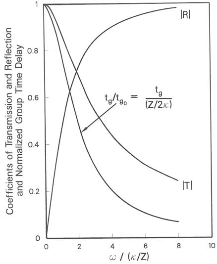
FIGURE 3.15 Magnitudes of the reflection and transmission coefficients and normalized group delay for a seismic wave normally incident on a displacement discontinuity as a function of normalized frequency; ω is circular frequency, ![]() is fracture stiffness, Z is seismic impedance, tg is group time delay, ¦R¦ is the coefficient of reflection, and ¦T¦ is the coefficient of transmission. From Pyrak-Nolte et al. (1990b).
is fracture stiffness, Z is seismic impedance, tg is group time delay, ¦R¦ is the coefficient of reflection, and ¦T¦ is the coefficient of transmission. From Pyrak-Nolte et al. (1990b).
laboratory in a pseudostatic loading test. Work by Pyrak-Nolte et al. (1990b) suggests that the dynamic values of ![]() may be higher, possibly owing to frictional lockup of asperities in contact.
may be higher, possibly owing to frictional lockup of asperities in contact.
Although ![]() in general must be measured, some simple special cases have been analyzed for purposes of validation of the theoretical concept. For the very simplified geometry of a row of two-dimensional cracks of length 2c (e.g., Figure 3.11) with a uniform spacing of 2l, the average displacement,
in general must be measured, some simple special cases have been analyzed for purposes of validation of the theoretical concept. For the very simplified geometry of a row of two-dimensional cracks of length 2c (e.g., Figure 3.11) with a uniform spacing of 2l, the average displacement, ![]() , due to stress,
, due to stress, ![]() , applied normal to the plane containing the row, is given by (Tada et al., 1973)
, applied normal to the plane containing the row, is given by (Tada et al., 1973)
where E and v are the Young's modulus and shear modulus, respectively, of the intact rock. The normal stiffness for this model can be found by combining this equation with Eq. 3.11:
Interestingly, because the expression for shear displacements under shear stress acting in the plane perpendicular to the cracks is identical to that for normal stress, the expressions for normal and shear stiffness also are equivalent, assuming frictional lockup of the contacting asperities between the cracks.
Using ![]() from Eq. 3.13, the wave equation can be solved to find the transmission and reflection coefficients for a row of cracks. Angel and Achenbach (1985) showed that the solution is equivalent at long wavelengths to that obtained for elastic wave scattering by a row of cracks. Myer et al. (1985) performed laboratory seismic measurements on an idealized fracture for which stiffness could be calculated by using Eq. 3.13 and found good agreement between their results and those predicted from the seismic displacement discontinuity model.
from Eq. 3.13, the wave equation can be solved to find the transmission and reflection coefficients for a row of cracks. Angel and Achenbach (1985) showed that the solution is equivalent at long wavelengths to that obtained for elastic wave scattering by a row of cracks. Myer et al. (1985) performed laboratory seismic measurements on an idealized fracture for which stiffness could be calculated by using Eq. 3.13 and found good agreement between their results and those predicted from the seismic displacement discontinuity model.
The seismic displacement discontinuity model has been compared with laboratory measurements on samples containing single natural fractures (Pyrak-Nolte, 1990a). These measurements showed that the fractures caused the frequency-dependent attenuation of both compressional and shear waves. The amount of attenuation decreased as the stiffness of the fracture increased with the addition of stress normal to the fracture. The seismic displacement discontinuity model successfully predicted the observed effects of the fractures.
If a fracture is modeled as an elastic interface, as noted above, no energy is lost in the system. To account for energy loss, which occurs when fluids or infillings such as clay are present in a fracture, a velocity discontinuity may be assumed. Solutions for Kelvin and Maxwell rheologies, which are two realizations of combined velocity and displacement discontinuity models, have been obtained (Myer et al., 1990a). Laboratory results indicate that the velocity discontinuity model provides an excellent representation of the attenuation of shear waves by
fractures containing clay and fluid of different chemistries (Suarez-Rivera et al., 1992). Field evaluation of the model is needed, however.
Appendix 3.A discusses the theory underlying this model.
Relationship to Hydraulic Properties
The geometry and volume of the void space control fluid flow and (as discussed earlier, under ''Shear Stress Conditions") can be used as a basis for predicting the effects of fractures on seismic wave propagation. There should therefore be qualitative, if not quantitative, relationships between hydraulic and seismic properties of fractures.
One property important to both hydraulic and seismic behavior is the stiffness of the fracture. In an elastic system, fracture stiffness determines the change in void volume resulting from a change in applied stress. Carlson and Gangi (1985) produced a unified model that describes both the elastic and hydraulic effects of fractures. An extra degree of freedom, which describes the statistics of asperity heights, is used. In laboratory tests on natural fractures, a rank correlation between stiffness, hydraulic conductivity, and seismic amplitude is observed (Pyrak-Nolte et al., 1987a; Myer, 1991). That is, the least-stiff fracture has the highest hydraulic conductivity and lowest transmitted wave amplitude; the converse is true for the stiffest fracture. Because there is a nonunique relationship between void geometry and stiffness, the relationship between permeability and stiffness also is nonunique. However, it would be of great practical benefit to establish even empirical relationships between these parameters.
Under some conditions, the dynamic stresses imposed on a fracture by a propagating wave can produce fluid motion, the magnitude of which is a function of the fracture permeability. The energy used in producing fluid flow in turn affects wave propagation. A well-studied example is the interaction of Stonley (tube) waves with fractures intersecting a borehole. Tang et al. (1991) developed a model that relates the attenuation of the Stonley wave to the permeability of the fracture. Results of these and other studies (e.g., Paillet et al., 1987) indicate that fractures are better modeled as a thin, stress-sensitive porous medium than as parallel plates.
ELECTRICAL PROPERTIES
Bulk Properties
A number of theories have been proposed to describe bulk electrical properties based on properties of the constituents. Most commonly, a rock is considered a two-component mixture, where the mineral grains are one component and the fluid (usually a liquid) occupying the voids between the grains is the other. The volume fraction occupied by the fluid is defined as the porosity.
An empirical relationship that relates bulk resistivity to pore fluid resistivity and porosity at low frequencies was established by Archie (1942):
where ![]() r is the bulk resistivity of the rock,
r is the bulk resistivity of the rock, ![]() w is the pore fluid resistivity, F is the formation factor, φ is the porosity, n is the cementation factor (approximately 1.5), and
w is the pore fluid resistivity, F is the formation factor, φ is the porosity, n is the cementation factor (approximately 1.5), and ![]() is a dimensionless parameter (approximately unity). This equation is known as Archie's law and has found wide application in estimating porosity from resistivity measurements. Several variations of the formula exist that are considered to be more accurate for certain rock types. Archie's law is discussed in terms of the equivalent channel model by Walsh and Brace (1984).
is a dimensionless parameter (approximately unity). This equation is known as Archie's law and has found wide application in estimating porosity from resistivity measurements. Several variations of the formula exist that are considered to be more accurate for certain rock types. Archie's law is discussed in terms of the equivalent channel model by Walsh and Brace (1984).
The bulk electrical conductivity also depends on fluid saturation in the pores, assuming the matrix is nonconductive. Empirical relationships have been found that relate the percent water saturation and clay concentration to the bulk conductivity (e.g., Simandoux, 1963).
At high frequencies, equations describing electric properties become more complex, and a number of theories have been published. Some of these are reviewed by Sihvola (1989). Based on the theory of self-similar systems, Sen et al. (1981) derived a mixture formula for a two-component system known as the Bruggeman-Hanai-Sen equation. In the direct current limit, this equation reduces to Archie's law. Reasonable agreement between the mixture formula and experimental data has been reported (Shen et al., 1985; Sihvola, 1989).
In low-porosity rocks with low-conductivity pore fluids, surface conduction along grain boundaries becomes a significant factor, requiring the addition of a surface conduction term to Archie's equation (Brace et al., 1965; Magnusson et al., 1987). Hence, surface conduction will give a higher bulk conductivity than if conductivity was attributed only to the pore fluid. For clay-bearing rocks, surface conduction is usually a significant factor. Expressions for the bulk conductivity of such rocks have been given by, for example, Waxman and Smits (1968). Their expression includes a term that takes into account the dependence of the mobility of exchange cations on pore water concentration and the clay cation exchange capacity per unit volume.
The electrical conductivity of rock can vary by several orders of magnitude, depending on rock type. The extensions of Archie's law discussed above give reasonable values of conductivity for low-porosity granites with conductivities on the order of 10-5 siemens per meter as well as porous brine-saturated sandstone with conductivities on the order of 1 siemen per meter.
The conductivities of rocks containing conductive minerals such as graphite, pyrite, or certain ore-bearing minerals cannot be described using Archie's law or similar formulas. In such cases, conduction is dominated by the volume fraction and conductivity of the mineral grains; the contributions from porosity and pore fluids are negligible.
The porosity of a fracture is localized in a very thin planar feature. For sparse fracture spacings the fracture porosity may not be significantly larger than the matrix porosity. However, if the fractures are connected, they will provide significant paths of conduction in the rock mass. Additionally, because the void space connectivity changes with stress, fracture conductivity is stress dependent. A fractured rock mass may therefore be visualized as a matrix of one conductivity containing thin sheets of a second stress-sensitive conductivity.
The effects of the presence of such features on the bulk properties discussed above require further study. Measurements of electrical properties of fractures have rarely been undertaken. However, some insights have been gained, as discussed below, from studies using fluid flow analogies for conduction.
Relationship Between Hydraulic and Electrical Properties
The idea of comparing the hydraulic and electrical properties of rock is not new. Simultaneous measurement of fluid permeability and electrical resistivity is in fact a well-established practice for core analysis in the oil industry. The hydraulic and electrical conductivities of rock should be related because of the similarity between the differential equations describing each process. If a fracture is modeled as two parallel plates, the flow rate per unit width is given by Eq. 3.2 and the permeability, K, by analogy with Darcy's law, is K = b2/12, so that
If the space between the plates is filled with an electrolyte, the electric current per unit width is proportional to the first power of the aperture according to Ohm's law
where ![]() is the resistivity of the electrolyte.
is the resistivity of the electrolyte.
From these equations it is seen that the volumetric flow rate, Q, is analogous to the electric current, I. The fluid pressure, P, is analogous to the electric potential, V, and the properties of the fluid are described by the dynamic viscosity, ![]() , and resistivity,
, and resistivity,![]() .
.
Brown (1987, 1989) assumed that the topography of the fracture surfaces varies slowly in the plane of the fracture (i.e., that the slopes are small) and that the parallel-plate results for the transport properties hold locally. Conservation of mass and charge also are assumed. Brown found that these conditions lead to Reynolds's equation for fluid flow:
and an analogous equation for the conduction of electricity:
The local aperture b is actually a function of the spatial coordinates in the plane of the fracture (i.e., b = b(x,y)). These differential equations can be used to model both fluid flow and transport of electric current through a rough fracture if the aperture distribution b(x,y ) is known. Using a fractal algorithm, Brown (1987, 1989) generated rough surfaces, and pairs of surfaces with the same fractal dimension were placed together to form a "fracture." Calculations of the volume flow rate and electric current fields of one such fracture are shown in Figure 3.16. The electric current is more diffuse over the fracture than the fluid flow. The fluid flow is more strongly affected by the surface roughness, with the large aperture channels playing the dominant role in transport.
This observation supports the conceptual model of Tsang and Tsang (1987) for channel flow through fractures. The difference between the fluid flow and electric current fields is due to their cubic versus linear dependence on aperture. Figure 3.17 shows an overlay of the left center portions of the flow fields shown in Figure 3.16. Note that in general the fluid flow and electric current vectors do not have the same orientations. In other words, fluid particles and charged ions take different paths through the fracture.
Model results have also demonstrated that the arithmetic average aperture, when used in the parallel-plate model, overestimates both the volume flow rate and the electric current through rough-walled fractures (Brown, 1989). This is due in part to the tortuous paths both fluid particles and charged ions must take around the surface roughness elements.
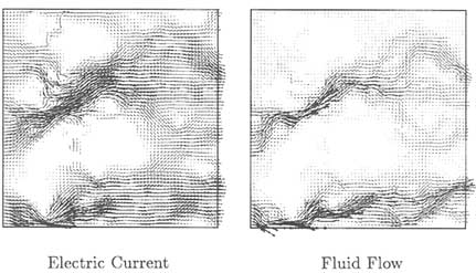
FIGURE 3.16 Electric current and volume flow rate fields of a fracture generated by using a fractal algorithm. The magnitude and direction of the local electric current and volume flow rate are represented by small arrows. From Brown (1989).
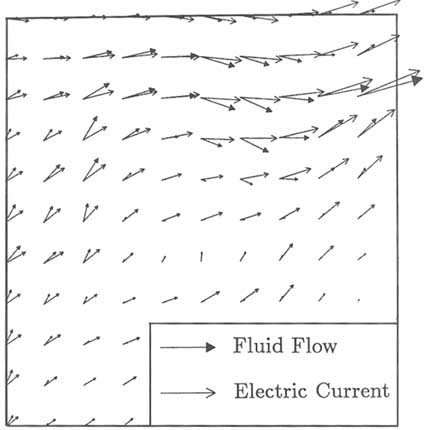
FIGURE 3.17 Overlay of the left center portions of the flow fields shown in Figure 3.16. From Brown (1989).
The relationship between hydraulic and electrical properties changes with deformation. Figure 3.18 compares hydraulic and electrical properties as a function of dimensionless aperture, bm/hrms, where bm is the mechanical aperture and hrms is the rms surface height of the fracture surfaces (Brown, 1989). Calculations were carried out for fractures generated by using surfaces with a range in fractal dimension (D). Points labeled "CV" result from apertures calculated by using conservation of volume (cf. "Normal Stress Effects" earlier in this chapter). The hydraulic (bh) and electric (be) apertures are nearly the same when the surfaces are widely separated (i.e., bm/hrms >> 1). However, be becomes progressively smaller than bh as the fracture closes. These results suggest that electrical conduc-
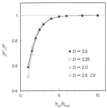
FIGURE 3.18 Ratio of the electric aperture (be) to the hydraulic aperture (bh) as a function of mechanical aperture (bm) and the rms height of the fracture surfaces (hrms) for fractures with different fractal dimensions (D). "CV" denotes conservation of volume. From Brown (1989).
tivity measurements underestimate the hydraulic conductivity of fractured rock and the total fracture volume by a percentage that increases as the fractures close.
The results of Brown (1989) are consistent with the "equivalent channel model" presented independently by Paterson (1983) and Walsh and Brace (1984), which explains the relationship between permeability and formation factor. The essence of the equivalent channel model is the existence of a "typical" pore geometry that describes the behavior of the system. These equivalent channels are assumed to have a simple geometry, for example, cylindrical tubes for the pores in sandstones and parallel plates for microcracks in granites. The channels may not be straight. That is, the path length of the fluid may be longer than the
nominal length of the specimen. Porosity (φ) is defined as the fractional area of pore space as observed on a cross section through the specimen, and tortuosity (![]() 2) is defined as the square of the ratio of the actual path length to the nominal path length.
2) is defined as the square of the ratio of the actual path length to the nominal path length.
For channels of constant cross section, such as cylindrical tubes or parallel plates, the microscopic geometry can be used to predict the macroscopic permeability (K) and formation factor (F) (Walsh and Brace, 1984):
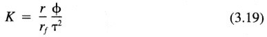
and
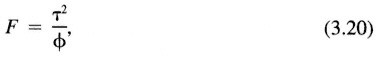
where r is the hydraulic radius (r = radius/2 for cylindrical tubes; r = b/2 for parallel plates), and rf is the shape factor (r f = 2 for cylindrical tubes; rf = 3 for parallel plates). In the derivation of Eqs. 3.19 and 3.20, tortuosity is assumed to be the same for the flow of fluid and electric current. By combining measurements of K and F, some useful information could conceivably be obtained about the pore geometry (i.e., a combination of ![]() , r, and rf).
, r, and rf).
Conventionally in core analysis the logarithm of permeability is plotted against the logarithm of the formation factor for many specimens of a given rock type from a particular oil reservoir. If a clear relationship is observed, electrical resistivity measurements from well logging can be used to estimate the permeability. Often, there is a linear relationship between the permeability and the formation factor in logarithmic coordinates (e.g., Archie, 1942; Walsh and Brace, 1984). The slope of the line defining the relationship is s, given by
The equivalent channel model shows that for fracture like pores s indicates how sensitive the tortuosity is to changes in fracture aperture through the following expression (Walsh and Brace, 1984):
where the subscript o indicates an arbitrary reference value. It appears that s is bounded between the values of 1 and 3. For s ÷1 the tortuosity is very sensitive to changes in aperture. It can be shown that for an ideal parallel-plate fracture, where the hydraulic aperture equals the electric aperture, s ð 3. Laboratory measurements on porous rock yield 1.5 ≤ s ≤ 2.8, with a typical value close to s = 2 (Walsh and Brace, 1984; Bernabe, 1986, 1988).
Figure 3.19 shows the logarithm of macroscopic permeability versus the logarithm of formation factor from numerical simulations of a hypothetical rough-walled fracture generated by using rough surfaces of fractal dimension D = 2.5 (Brown, 1989). The points along this curve correspond to various values of dimensionless aperture (bm/h rms; see Figure 3.18). The curve is nonlinear; its slope varies from about -3 when the fracture walls are separated (bm/hrms > 4.25) to about -2 when the walls are in intimate contact (bm/hrms << 4.25). This implies that when the surfaces are widely separated the tortuosity is not sensitive to changes in aperture. This agrees with intuition because, when the surfaces are separated, changes in aperture should not significantly change the lengths of the
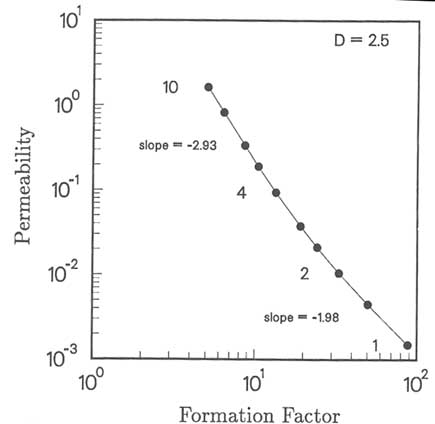
FIGURE 3.19 Permeability as a function of formation factor for a fracture composed of surfaces with fractal dimension D = 2.5. The permeability and formation factor were computed by using the hydraulic and electric apertures for the fracture. The labels 1, 2, 4, and 10 refer to the dimensionless aperture bm/hrms. Slopes are given for the two intervals 1–2 and 4–10. From Brown (1989).
streamlines. When the fracture surfaces are in contact, however, the tortuosity becomes increasingly sensitive to changes in aperture, as shown by the change of slope in Figure 3.19. Therefore, the parallel-plate model, which does not account for the extra path length, will overestimate both the volume flow rate and the electric current.
SUMMARY
With few exceptions, any fracture can be visualized as two rough surfaces in contact. In cross section the voids and solid areas representing asperities in contact are analogous to the pores and grains of porous media. Consequently, the general equations describing flow, transport, and chemical processes are equally applicable in fractures and porous media. One major difference between the two is that the void space of the fracture is interconnected in one plane, so the fracture is best described as a two-dimensional porous medium. The second major difference is that the void space of fractures tends to be more cracklike in shape than that of porous media. This difference leads to greater stress-sensitive properties of fractures. The observed flow and transport behavior of fractures can, to a great extent, be explained in terms of the geometry of the void space and the changes in this geometry brought about by changes in effective stress and fluid chemistry.
Further work is needed to characterize the statistical properties of fracture void space and how these properties vary with rock type, geological origin, and changes in stress. Although understanding the roughness of surfaces is an important element of such studies, more emphasis is needed on direct characterization of the void space; it is not at all clear what relationship, if any, there is between the roughness of the fracture surfaces and the geometric properties of the void space that remains when the fractures are in a mated condition. Both the geometric properties of the void space and the fracture surface roughness need to be described as stochastic processes.
The change in fracture void geometry owing to an applied normal stress can be effectively modeled for many rock types, assuming the rock is a linearly elastic material. This assumption is not sufficient when the applied stresses involve a combination of normal and shear stresses. Even though extensive effort has been directed toward measuring the mechanical deformation and strength of fractures under combined normal and shear stresses, there is only rudimentary understanding of the relationship between the measured mechanical response and changes in void geometry, which affect flow or transport properties.
The basic phenomenological relationships between single-phase flow, void geometry, and changes in normal stress are well understood. The cubic law adequately models flow under laminar conditions at any point in a fracture. However, under changing effective stress conditions, there is not an equivalence between the change in aperture required by the cubic law and the macroscopic
deformation of the fracture under changing stress. Additional measurements of void volume change can be made, but they are cumbersome. The most feasible alternative is direct measurements of permeability, either in the laboratory or in the field, under effective stress representative of in situ conditions. This further implies that models that incorporate a coupling of stress and flow should do so through a permeability-stress relationship, rather than through a permeability-aperture relationship.
Very little is understood about the basic phenomenological relationships between single-phase flow and fracture void geometry under combined normal and shear stresses, or between multiphase multicomponent flow and fracture void geometry under any conditions. More emphasis should be placed on measurements on natural fractures or casts of natural fractures. It is clear that these processes depend strongly on the statistical properties of the void space, including the interconnectivity and spatial distribution, but it is not yet clear what statistical measures are representative of typical fractures.
Although direct measurement of flow properties is required, there is still a need for developing quantitative relationships between microscopic measurements of fracture void geometry and macroscopic flow properties. Direct measurements of fracture aperture, such as field measurements using "feeler" gauges, should be used in engineering practice in the same manner as measurements of pore sizes in rock. Methods for using microscopic void geometry to predict macroscopic flow properties also should be investigated. For example, effective medium theory and critical path analyses (Doyen, 1988; David et al., 1990) have been applied to describing flow throughout the three-dimensional void structure of porous rock. These or other techniques, when combined with analysis of void closure under stress, could lead to a better quantitative understanding of the relationships between void structure and flow in fractures.
For many engineering applications, detailed analysis of fracture void space or direct measurements of flow and transport properties may not be feasible. There is a need to establish relationships between the geological origin of fractures and flow and transport properties. As discussed previously, the geological history of a fracture will have important effects on its surface characteristics and hence on hydrological properties. The data bases needed for such relationships, such as those established by Barton et al. (1985), should be expanded.
The presence of fractures in a rock mass causes a reduction in seismic velocity and an increase in attenuation. These two effects form the basis for characterization of fractures by seismic methods. The effects of fracture properties on seismic velocity are well understood. Changes in velocity arise primarily from changes in the effective elastic modulus of the rock. Attenuation arises from a number of processes, including scattering, fluid motion, and viscous damping. Further work is required to develop quantitative predictive relationships for these effects. The incentive for pursuing such research is that the effects of fractures
on attenuation are usually considerably greater, in terms of percent changes, than their effects on velocities.
Depending on seismic wavelengths, fractures can be represented by effective properties of the bulk medium or as discrete entities. Information gained from seismic measurements when fractures are represented by effective properties is limited to fracture density and orientation assuming fractures result in anisotropic elastic properties. Modeling of discrete fractures has the potential to provide information on location and orientation. Further testing at field scales is needed to assess the applicability of the discrete fracture theories discussed in this chapter.
Electrical conductivity is strongly related to porosity of the rock mass. The contribution of fractures to this porosity is the primary basis for use of electrical measurements for characterizing fractured rock masses. This porosity, however, is localized in the plane of the fracture. An area requiring further study is the effect of this localization on bulk effective properties that are measured in the field.
Recent studies have indicated that qualitative, and perhaps quantitative, relationships exist between the hydrological properties of single fractures and their geophysical properties. Additional theoretical, laboratory, and field-scale work is needed to confirm and improve the understanding of these relationships.
APPENDIX 3.A
SEISMIC DISPLACEMENT DISCONTINUITY THEORY
The seismic displacement discontinuity theory has been applied to modeling of cross-hole measurements in a basalt rock mass (King et al., 1986). P-wave measurements were made in four horizontal drillholes spaced 3 m apart in the wall of a drift (Figure 3.A1) at a depth of about 46 m above the water table. The fracture characteristics of the basalt are shown schematically in Figure 3.A1. The primary fracture set, which is nearly vertical, was formed between basalt columns that range in thickness from about 0.2 to 0.4 m. A secondary cross-cutting fracture set also is present. The wavelength of the P-waves is about 0.1 m.
The effects of the primary vertical fracture set on P-wave propagation are illustrated in Figure 3.A2. This figure shows typical examples of the first arriving P-wave pulses for three different borehole pairs. The pulse labeled ''C1-C2" propagated between boreholes C1 and C2 (Figure 3.A1) in a direction parallel to the primary fracturing. The pulse "C4-C2" propagated obliquely to the primary
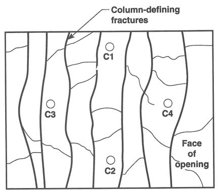
FIGURE 3.A1 Illustration of borehole configuration and fracture characteristics in crosshole field test. From Peterson et al. (1993).
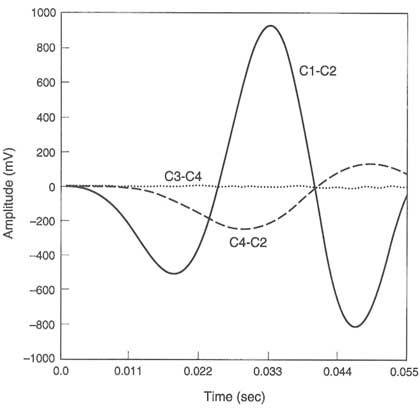
FIGURE 3.A2 Typical first arriving P-wave pulses from different borehole pairs. From Peterson et al. (1993).
fractures, whereas pulse "C3-C4" propagated orthogonally to the primary fractures. The differences in arrival times shown in the figure reflect the differences in wave velocities for the different propagation directions. It is seen that waves traveling obliquely to the primary fractures were slowed and attenuated with respect to fracture-parallel waves. The waves were almost completely attenuated in the direction perpendicular to the fractures.
In modeling the field results it was assumed that the observed differences in arrival times were due to the effects of the vertical fractures. In other words, except for differences due to travel path length, it is assumed that pulses traveling between all boreholes would be identical to those propagating vertically between C1 and C2 were it not for the effects of the vertical fractures. Pulses propagating between C1 and C2 were therefore used as reference pulses. The time delays and attenuations of pulses traveling in other directions were predicted by using
the seismic displacement discontinuity theory. The only parameters that needed to be estimated in the analysis were fracture frequency and fracture stiffness.
Figure 3.A3 shows results of the modeling of a typical pulse propagated between holes C4 and C2. Shown are the reference pulse, the measured pulse, and the predicted pulse assuming the wave propagated at a 45° angle of incidence across three fractures, each with a stiffness of 5 × 10¹¹ Pa/m. It is seen that the seismic displacement discontinuity theory is able to predict the time delay, amplitude, and frequency characteristics of the measured pulse with a high degree of accuracy. For waves traveling between C3 and C4, six fractures were assumed because of the increased travel distance, but the stiffness of each fracture was held constant at 5 × 10¹¹ Pa/m. As can be seen in Figure 3.A4, the theory predicted that the increased number of fractures should completely attenuate the pulse.
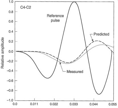
FIGURE 3.A3 Comparison of predicted and observed results for a pulse traveling between boreholes C4 and C2. From Peterson et al. (1993).
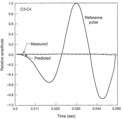
APPENDIX 3.BGRAVITY-DRIVEN INFILTRATION FLOW INSTABILITY
Consider a rock unit containing extensive, initially dry, inclined fractures that outcrop at the surface. A typical fluid source for infiltration into such fractures is surface ponding resulting from a locally intense rainfall event. Preferential flow associated with local fracture heterogeneity or differential supply of fluid will introduce finite-amplitude perturbations to the infiltration front, as shown in Figure 3.B1 for a transparent analog system. The driving force in the advancing front is the sum of gravitational (![]() g) and capillary (
g) and capillary (![]() c) gradients. Assuming that
c) gradients. Assuming that
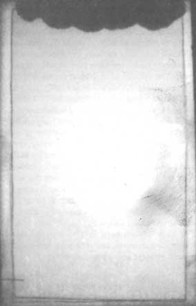
FIGURE 3.B1 Stable infiltration front initiated from application of a finite slug of fluid (black) into an initially dry fracture (white). Note that there are five significant perturbations to the front. From Nicholl et al. (1993b).
air (![]() a) and water (
a) and water (![]() w) entry pressure heads are independent of flow velocity,
w) entry pressure heads are independent of flow velocity, ![]() c can be approximated as
c can be approximated as

where Lf describes the down-gradient length of the connected fluid column (Nicholl et al., 1992). During the initial stage of infiltration, fluid is freely available to the fracture; hence, no drainage behind the front occurs (![]() a = 0) and capillary forces act to reinforce flow (
a = 0) and capillary forces act to reinforce flow (![]() c > 0). Preferential flow occurs to regions of small Lf, thereby damping the initial finite-amplitude perturbations and stabilizing the front.
c > 0). Preferential flow occurs to regions of small Lf, thereby damping the initial finite-amplitude perturbations and stabilizing the front.
If fluid supply to the fracture is interrupted (i.e., the fluid supply becomes exhausted), the front can only advance by draining pores along its trailing edge. The introduction of a drainage pressure (![]() a < 0) causes
a < 0) causes ![]() c to reverse direction and oppose flow. As a result, flow to the front is redistributed from regions of small Lf (large
c to reverse direction and oppose flow. As a result, flow to the front is redistributed from regions of small Lf (large ![]() c) to regions of large Lf (small
c) to regions of large Lf (small ![]() c) that develop into fingers (Figure 3.B2). The unstable front therefore bypasses significant portions of the fracture plane, advancing farther and faster than would be expected for an equivalent uniform front. The velocity of individual fingers is a function of system hydraulic parameters,
c) that develop into fingers (Figure 3.B2). The unstable front therefore bypasses significant portions of the fracture plane, advancing farther and faster than would be expected for an equivalent uniform front. The velocity of individual fingers is a function of system hydraulic parameters, ![]() c and Lf (Nicholl et al., 1992). As a finger advances, it leaves a partially wetted region behind (Figure 3.B2). The consequent loss of fluid causes the finger to slow and eventually halt in the fracture. Individual fingers therefore terminate in a fluid cluster that is "frozen" in place by capillary forces.
c and Lf (Nicholl et al., 1992). As a finger advances, it leaves a partially wetted region behind (Figure 3.B2). The consequent loss of fluid causes the finger to slow and eventually halt in the fracture. Individual fingers therefore terminate in a fluid cluster that is "frozen" in place by capillary forces.
An unstable front will bypass significant portions of the fracture plane. Consequently, the volume of rock brought into hydraulic communication by a single infiltration event will be larger than that expected for an equivalent uniform front. Furthermore, at times short with respect to matrix imbibition and evaporative redistribution, the wetted structure created by unstable infiltration will have a significant effect on subsequent fracture infiltration. Ensuing infiltration events will preferentially follow the existing wetted structure. As the flow path is prewetted, finger velocity is increased over that observed in a dry fracture and very little fluid is lost during passage (Nicholl et al., 1993a,b). In effect, virtually the entire volume of an infiltration event is applied to the frozen fluid clusters associated with the previous event, restarting their movement and providing a mechanism for rapid recharge and solute transport.
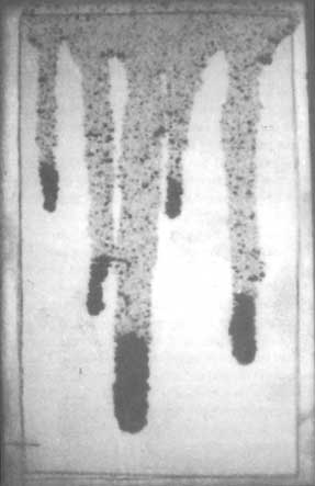
FIGURE 3.B2 Fingers originating from the stable front seen in Figure 3.B1. Partially saturated regions (mottled regions) are wetted near field capacity of the analog fracture. Courtesy of R. J. Glass.
APPENDIX 3.C
INFLUENCE OF TWO-PHASE STRUCTURE ON FRACTURE PERMEABILITY AND SOLUTE TRANSPORT
Under steady-state conditions, flow in a single-phase along the plane of a fracture is confined to the connected network of apertures filled by that phase. Decreasing phase saturation reduces the fraction of the fracture plane available for flow. The resultant decrease in cross-sectional area and increased flow tortuosity reduces the relative permeability for the phase.
Nicholl and Glass (1994) used a transparent analog rough-walled fracture to explore the effects of phase structure on fluid permeability and solute dispersion. Flow through the connected phase of a two-phase structure exhibited a channelization that was not observed under single-phase conditions (Figures 3.C1, 3.C2, and 3.C3). Path tortuosity of the channelized flow was observed to increase with complexity of the phase structure and size of the entrapped regions. Disconnected regions filled by the flowing phase are entirely isolated from flow under steady-state conditions. In addition, even in the connected regions, highly tortuous flow paths tend to bypass significant portions of the connected phase structure. This creates dead zones that do not actively participate in flow but communicate with active regions through diffusion. As a result, the average cross-sectional area of the connected phase structure is larger than the effective flow area.
For phase structures formed under nonequilibrium conditions, aperture filling may not follow a simple pressure/size relationship (Glass, 1993), further complicating the phase structure/permeability relationship. The fluid phase shown in Figure 3.C1 occupies 81.2 percent of the fracture plane. However, fluid permeability was only 14.3 percent of that measured at 100 percent saturation.
As expected from the previous discussion, two-phase wetted structure significantly affects solute dispersion. Flow channelization creates differential advection in the plane of the fracture (Figures 3.C2 and 3.C3). Velocity differentials introduced by local variations in cross-sectional area also act to increase dispersion. Dead zones created by flow tortuosity act to significantly extend the tail of the residence time distribution curve.
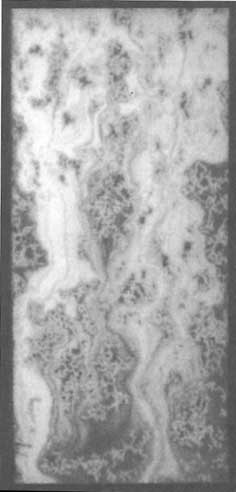
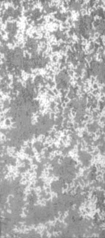
FIGURE 3.C2 Tracer pulse consisting of clear water entering the two-phase wetted structure in Figure 3.C1 from a constant flow boundary. From Nicholl and Glass (1994).
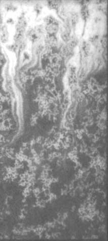
FIGURE 3.C3 Further development of the tracer pulse shown in Figure 3.C2. Note wholly isolated regions and dead zones that communicate by diffusion. From Nicholl and Glass (1994).
REFERENCES
Adamson, A. W. 1990. Physical Chemistry of Surfaces, 5th ed. New York: John Wiley & Sons, 777 pp.
Angel, Y. C., and J. D. Achenbach. 1985. Reflection and transmission of elastic waves by a periodic array of cracks. Journal of Applied Mechanics, 52:33–41.
Archambault, G., M. Fortin, D. E. Gill, M. Aubertin, and B. Ladanzi. 1990. Experimental investigations for an algorithm simulating the effect of variable normal stiffness on discontinuities shear strength. Pp. 141–148 in Rock Joints, Proceedings of the International Symposium on Rock Joints, Loen, Norway, W. Barton, and E. Stephansson, eds. Rotterdam: A. A. Balkema.
Archie, G. E. 1942. The electrical resistivity log as an aid in determining some reservoir characteristics. Transactions of the American Institute of Mechanical Engineering, 146:54–62.
Bandis, S. C. 1990. Mechanical properties of rock joints. Pp. 125–140 in Rock Joints, Proceedings of the International Symposium on Rock Joints, Loen, Norway, W. Barton and E. Stephansson, eds. Rotterdam: A. A. Balkema.
Bandis, S., A. C. Lumsden, and N. R. Barton. 1981. Experimental studies of scale effects on the shear behavior of rock joints. International Journal of Rock Mechanics and Mining Science and Geomechanics Abstracts, 18:1–21.
Barton, N. 1973. Review of a new shear-strength criterion for rock joints. Engineering Geology, 7:287–332.
Barton, N., S. Bandis, and K. Bakhtor. 1985. Strength, deformation and conductivity coupling in rock joints. International Journal of Rock Mechanics and Mining Sciences and Geomechanics Abstracts, 22(3):121–140.
Bath, M. 1974. Spectral Analysis in Geophysics. New York: Elsevier.
Bendat, J. S., and A. G. Piersol. 1971. Random Data, Analysis and Measurement Procedures. New York: John Wiley & Sons.
Bernabe, Y. 1986. Pore volume and transport properties changes during pressure cycling of several crystalline rocks. Mechanics and Materials, 5:235–249.
Bernabe, Y. 1988. Comparison of the effective pressure law for permeability and resistivity formation factor in Chelmsford granite. Pure and Applied Geophysics, 127:607–625.
Billaux, D., and S. Gentier. 1990. Numerical and laboratory studies of flow in a fracture. Pp. 369–373 in Rock Joints, Proceedings of the International Symposium on Rock Joints, Loen, Norway, W. Barton and E. Stephansson, eds. Rotterdam: A. A. Balkema.
Biot, M. A. 1956. Theory of Propagation of Elastic Waves in a Fluid-Saturated Porous Solid. I. Low-Frequency Range. Journal of the Acoustics Society of America, 28(2):168.
Brace, W. F., A. S. Orange, and T. R. Madden. 1965. Effect of pressure on the electrical resistivity of water-saturated crystalline rocks. Journal of Geophysical Research, 70:5669–5678.
Broadbent, S. R., and J. M. Hammersley. 1957. Percolation Processes. I. Crystals and Mazes. Cambridge Philosophical Society Proceedings, 53:629–641.
Brown, S. R. 1987. Fluid flow through rock joints: the effect of surface roughness. Journal of Geophysical Research, 92(82):1337–1347.
Brown, S. R. 1989. Transport of fluid and electric current through a single fracture. Journal of Geophysical Research, 94(B7):9429–9438.
Brown, S. R., and C. H. Scholz. 1985. Broad bandwidth study of the topography of natural rock surfaces. Journal of Geophysical Research, 90:575–582.
Brown, S. R., and C. H. Scholz. 1986. Closure of rock joints. Journal of Geophysical Research, 91:4939–4948.
Brown, S. R., R. L. Kranz, and B. P. Bonner. 1986. Correlation between the surfaces of natural rock joints. Geophysics Research Letter, 13:1430–1433.
Budiansky, B., and R. J. O'Connell. 1980. Bulk dissipation in heterogeneous media. Solid Earth Geophysics and Geotechnology, New York: American Society of Mechanical Engineers, 42:1.
Carlson, R. L., and A. F. Gangi. 1985. Effect of cracks on the pressure dependence of P-wave velocities in crystalline rocks. Journal of Geophysical Research, 90(B10):8675–8684.
Carter, J. J. 1990. The effects of clay coating on fluid flow through simulated rock fractures. M.S. thesis, University of California, Berkeley.
Chouke, R. L., P. van Meurs, and C. van der Poel. 1959. The instability of slow immiscible, viscous liquid-liquid displacements in porous media. Transactions of the American Institute of Mining Engineers, 216:T.P. 8073.
Cook, A. M., L. R. Myer, N. G. W. Cook, and F. M. Doyle. 1990. The effect of tortuosity on flow through a natural fracture. Pp. 371–378 in Rock Mechanics Contributions and Challenges, Proceedings of the 31st U.S. Symposium on Rock Mechanics, W. A. Hustrulid and G. A. Johnson, eds. Rotterdam: A. A. Balkema.
David, C., Y. Gueguen, and G. Pampoukis. 1990. Effective medium theory and network theory applied to the transport properties of rock. Journal of Geophysical Research, 95(B5):6993–7005.
de Gennes, P. G. 1985. Wetting: statics and dynamics. Reviews of Modern Physics, 57:827–863.
Doyen, P. M. 1988. Permeability, conductivity, and pore geometry of sandstone. Journal of Geophysical Research, 93(B7):7729–7740.
Dussan, V. 1979. On the spreading of liquids on solid surfaces: static and dynamic contact lines. Annual Review of Fluid Mechanics, 11:371–400.
Einstein, H. H., and C. H. Dowding. 1981. Shear resistance and deformability of rock discontinuities. Pp. 177–219 in Physical Properties of Rocks and Minerals, Y. S. W. Touloukian, R. Judd, and R. E. Ray, eds. New York: McGraw-Hill.
Esaki, T., H. Hojo, T. Kimura, and N. Kameda. 1991. Shear-flow coupling test on rock joints. Pp. 389–392 in Proceedings of 7th International Congress on Rock Mechanics. Rotterdam: A. A. Balkema.
Feder, J. 1988. Fractals. New York: Plenum Press, 283 pp.
Gale, J. E. 1982. The effects of fracture type (induced versus natural) on the stress-fracture closure fracture permeability relationships. Pp. 290–298 in Issues in Rock Mechanics, Proceedings of the 23rd U.S. Symposium on Rock Mechanics, R. Goodman and F. Henze, eds. New York: Society of Mining Engineers of AIME.
Gale, J. E. 1987. Comparison of coupled fracture deformation and fluid flow models with direct measurements of fracture pore structure and stress-flow properties. Pp. 1213–1222 in Rock Mechanics, Proceedings of the 28th U.S. Symposium on Rock Mechanics, I. W. Farmer, J. J. K. Daemen, C. S. Desai, C. E. Glass, and S. P. Neuman, eds. Rotterdam: A. A. Balkema.
Gale, J. 1990. Hydraulic behavior of rock joints. Pp. 351–362 in Rock Joints, Proceedings of the International Symposium on Rock Joints, Loen, Norway, W. Barton and E. Stephansson, eds. Rotterdam: A. A. Balkema.
Gale, J. E., and E. J. Reardon. 1984. Effect of groundwater geochemistry on the permeability of grouted fractures. Canadian Geotechnical Journal, 21(1):8–20.
Gentier, S., and J. Ries. 1990. Quantitative description and modeling of joint morphology. Pp. 375–382 in Rock Joints, Proceedings of the International Symposium on Rock Joints, Loen, Norway, W. Barton and E. Stephansson, eds. Rotterdam: A. A. Balkema.
Glass, R. J. 1993. Modeling gravity-driven fingering in rough-walled fractures using modified percolation theory. Pp. 2042–2052 in Proceedings of the Fourth Annual International High-Level Radioactive Waste Management Conference. La Grange Park, Ill.: American Nuclear Society.
Glass, R. J., and D. L. Norton. 1992. Wetted region structure in horizontal unsaturated fractures: water entry through the surrounding porous matrix. Pp. 717–726 in Proceedings of the Third Annual International High-Level Radioactive Waste Management Conference. La Grange Park, Ill.: American Nuclear Society.
Goodman, R. E. 1976. Methods of Geological Engineering Discontinuous Rock. St. Paul: West Publishing Co.
Hakami, E., and N. Barton. 1990. Aperture measurements and flow experiments using transparent replicas of rock joints. Pp. 383–390 in Rock Joints, Proceedings of the International Symposium on Rock Joints, Loen, Norway, W. Barton and E. Stephansson, eds. Rotterdam: A. A. Balkema.
Heard, H. C., and L. Page. 1982. Elastic moduli, thermal expansion, and inferred permeability of two granites to 350°C and 55 megapascals. Journal of Geophysical Research, 87(B11):9340–9348.
Homsy, G. M. 1987. Viscous fingering in porous media. Annual Review of Fluid Mechanics , 19:271–311.
Hopkins, D. C., N. G. W. Cook, and L. R. Myer. 1990. Normal joint stiffness as a function of spatial geometry and surface roughness. Pp. 203–210 in Rock Joints, Proceedings of the International Symposium on Rock Joints, Loen, Norway, W. Barton and E. Stephansson, eds. Rotterdam: A. A. Balkema.
Hudson, J. A. 1980. Overall properties of a cracked solid. Mathematical Proceedings of the Cambridge Philosophical Society, 88:371.
Iwai, K. 1976. Fundamental studies of fluid flow through a single fracture. Ph.D. thesis, University of California, Berkeley.
Jones, F. O. 1975. A laboratory study of the effects of confining pressure on fracture flow and storage capacity in carbonate rocks. Journal of Petroleum Technology, Jan., pp. 21–27.
Jones, T. D. 1986. Pore fluids and frequency-dependent wave propagation in rocks. Geophysics, 51(10):1939–1953.
Khilar, K. L., and H. S. Folger. 1984. The existence of a critical salt concentration for particle release. Journal of Colloid and Interface Science, 101(1):214–224.
King, M. S., L. R. Myer, and J. J. Rezowalli. 1986. Experimental studies of elastic-wave propagation in a columnar-pointed rock mass. Geophysical Prospecting, 34(8):1185–1199.
Kranz, R. L., A. D. Frankel, T. Engelder, and C. H. Scholz. 1979. The permeability of whole and jointed Barre granite. International Journal of Rock Mechanics and Mining Science and Geomechanics Abstracts, 16:225–234.
Kutter, H. K., and F. Otto. 1990. Influence of parallel and cross joints on shear behavior of rock discontinuities. Pp. 243–250 in Rock Joints, Proceedings of the International Symposium on Rock Joints, Loen, Norway, W. Barton and E. Stephansson, eds. Rotterdam: A. A. Balkema.
Lamb, H. 1932. Hydrodynamics, 6th ed. Cambridge: Cambridge University Press.
Lehner, F. K., and J. Bataille. 1984. Nonequilibrium thermodynamics of pressure solution. Report No. 25, Division of Engineering, Brown University, Providence, R.I., 52 pp.
Magnusson, K. A., S. Carlsten, and O. Olsson. 1987. Crosshole investigations—physical properties of core samples from boreholes F1 and F2. Stripa Project IR 87-10. Stockholm: Swedish Nuclear Fuel and Waste Management Company (SKB).
Makurat, A. 1985. The effect of shear displacement on the permeability of natural rough joints. Pp. 99–106 in Proceedings Hydrogeology of Rocks of Low Permeability, Tucson, Ariz., International Association of Hydrogeologists, Memoires XVII .
Mandelbrot, B. B. 1982. The Fractal Geometry of Nature. San Francisco: W. H. Freeman and Co.
Miller, S. M., P. C. McWilliams, and J. C. Kerkering. 1990. Ambiguities in estimating fractal dimensions of rock fracture. Pp. 471–478 in Rock Mechanics Contributions and Challenges, Proceedings of the 31th U.S. Symposium on Rock Mechanics, W. A. Hustrulid and G. A. Johnson, eds. Rotterdam: A. A. Balkema.
Mindlin, R. D. 1949. Compliance of elastic bodies in contact, Journal of Applied Mechanics, 16:259–269.
Mindlin, R. D., and H. Deresiewicz. 1953. Elastic spheres in contact under varying oblique forces. Journal of Applied Mechanics, 20:327–344.
Mitchell, S. K. 1993. Fundamentals of Foil Behavior, 2d ed. New York: John Wiley & Sons.
Moreno, L., Y. W. Tsang, C. F. Tsang, F. V. Hale, and I. Neretnieks. 1988. Flow and transport in a single fracture: a stochastic model and its relation to some field observations. Water Resources Research, 24(12):2033–2048.
Myer, L. 1991. Hydromechanical and seismic properties of fractures. Pp. 397–409 in Proceedings of the 7th International Rock Mechanics Congress, vol. 1
Myer, L. R., D. Hopkins, and N. G. W. Cook. 1985. Effects of contact area of an interface on acoustic wave transmission. Pp. 549–556 in Research and Engineering Applications in Rock Mechanics, Proceedings of the 26th U.S. Symposium on Rock Mechanics. Rotterdam: A. A. Balkema.
Myer, L. R., L. S. Pyrak-Nolte, and N. G. W. Cook. 1990a. Effect of single fractures on seismic wave propagation. Pp. 476–473 in Rock Joints, Proceedings of the International Symposium on Rock Joints, Loen, Norway, W. Barton and E. Stephansson, eds. Rotterdam: A. A. Balkema.
Myer, L. R., L. J. Pyrak-Nolte, D. Hopkins, and N. G. W. Cook. 1990b. Seismic characterization of fracture properties. Pp. 908–914 in Proceedings of First Annual International High-Level Radioactive Waste Management Conference, vol. 1. La Grange Park, Ill.: American Nuclear Society.
Nelson, P. H., R. Rachiele, and J. S. Remer. 1981. Water inflow into boreholes during the Stripa Heater Experiments. LBL-12574, Lawrence Berkeley Laboratory, Berkeley, Calif.
Nicholl, M. J., and R. J. Glass. 1994. Wetting phase permeability in a partially saturated horizontal fracture. Pp. 2007–2019 in Proceedings of the 5th International Conference on High-Level Radioactive Waste Management. La Grange Park, Ill.: American Nuclear Society.
Nicholl, M. J., R. J. Glass, and H. A. Nguyen. 1992. Gravity-driven fingering in unsaturated fractures. Pp. 321–332 in High-Level Radioactive Waste Management, Proceedings of the Third Annual International Conference, vol. 1. La Grange Park, Ill.: American Nuclear Society.
Nicholl, M. J., R. J. Glass, and H. A. Nguyen. 1993a. Wetting front instability in an initially wet unsaturated fracture. Pp. 2061–2070 in Proceedings of the Fourth Annual International High-Level Radioactive Waste Management Conference, vol. 2. La Grange Park, Ill.: American Nuclear Society.
Nicholl, M. J., R. J. Glass, and H. A. Nguyen. 1993b. Small scale behavior of single gravity-driven fingers in an initially dry fracture. Pp. 2023–2032 in Proceedings of the Fourth Annual International High-Level Radioactive Waste Management Conference, vol. 2. La Grange Park, Ill.: American Nuclear Society.
Nolte, D. D., L. J. Pyrak-Nolte, and N. G. W. Cook. 1989. The fractal geometry of flow paths in natural fractures in rock and the approach to percolation. PAGEOPH, 131(1/2):271.
Noorishad, J., C. F. Tsang, and P. A. Witherspoon. 1984. Coupled thermal-hydraulic-mechanical phenomena in saturated fractured porous rocks: numerical approach. Journal of Geophysical Research, 89(B12):10365–10375.
Ohnishi, Y., and P. G. R. Dharmaratra. 1990. Shear behavior of physical models of rock joints under constant normal stiffness conditions. Pp. 267–273 in Rock Joints, Proceedings of the International Symposium on Rock Joints, Loen, Norway, W. Barton and E. Stephansson, eds. Rotterdam: A. A. Balkema.
Olsson, W. A. 1992. The effect of slip on the flow of fluid through a fracture. Geophysics Research Letters, 19(6):541–543.
Paillet, F. L., A. E. Hess, C. H. Cheng, and E. Hardin. 1987. Characterization of fracture permeability with high-resolution vertical flow measurements during borehole pumping. Ground Water, 25(1):28–40.
Papaliangas, T., A. C. Lumsden, S. A. Hencher, and S. Manolopoulou. 1990. Shear strength of modeled filled rock joints. Pp. 275–282 in Rock Joints, Proceedings of the International Symposium on Rock Joints, Loen, Norway, W. Barton and E. Stephansson, eds. Rotterdam: A. A. Balkema .
Paterson, M. S. 1983. The equivalent channel model for permeability and resistivity in fluid-saturated rocks—a reappraisal. Mechanics and Materials, 2(4):345–352.
Patton, D. F. 1966. Multiple modes of stress failure in rock. P. 509 in Proceedings of the First International Congress on Rock Mechanics, vol. 1. Lisbon: Bertrand.
Persoff, P., K. Pruess, and L. Myer. 1991. Two-phase flow visualization and relative permeability measurement in transparent replicas of rough-walled rock fracture. Lawrence Berkeley Laboratory Report 30161, presented at the 16th Workshop on Geothermal Reservoir, Engineering, Stanford, Calif.
Peterson, J. E., Jr., D. Hopkins, and L. Myer. 1993. Application of seismic displacement discontinuity theory to Hanford data. Pp. 1006–1009 in Expanded Abstracts with Biographies, 1993 Technical Program: 63d Annual Meeting and International Exhibition, Society of Exploration Geophysicists.
Piggot, A. R., and D. Elsworth. 1990. Laboratory studies of transport within a single rock fracture. Pp. 397–404 in Rock Joints, Proceedings of the International Symposium on Rock Joints, Loen, Norway, W. Barton and E. Stephansson, eds. Rotterdam: A. A. Balkema.
Power, W. L., and T. E. Tullis. 1991. Euclidean and fractal models for the description of rock surface roughness. Journal of Geophysical Research , 96(B1):415–424.
Power, W. L., T. E. Tullis, S. R. Brown, G. N. Boitnott, and C. H. Scholz. 1987. Roughness of natural fault surfaces. Geophysics Research Letters, 14:29–32.
Pruess, K., and Y. W. Tsang. 1990. On two-phase relative permeability and capillary pressure of rough-walled rock fractures. Water Resources Research, 26(9):1915–1926.
Pyrak-Nolte, L. J., L. R. Myer, N. G. W. Cook, and R. A. Witherspoon. 1987a. Hydraulic and mechanical properties of natural fractures in low permeability rock. Pp. 225–232 in Proceedings of 6th International Congress of Rock Mechanics, vol. I. Rotterdam: A. A. Balkema.
Pyrak-Nolte, L. J., L. R. Myer, and N. G. W. Cook. 1987b. Seismic visibility of fractures. Pp. 47–56 in Rock Mechanics, Proceedings of the 28th U.S. Symposium on Rock Mechanics. Rotterdam: A. A. Balkema.
Pyrak-Nolte L. J., N. G. W. Cook, and D. D. Nolte. 1988. Fluid percolation through single fractures. Geophysics Research Letters, 15(11):1247–1250.
Pyrak-Nolte, L. J., N. G. W. Cook, and L. R. Myer. 1990a. Stratified percolation model for saturated and unsaturated flow through natural fractures. Pp. 551–558 in Proceedings of First Annual International High-Level Radioactive Waste Management Conference, vol. 1. La Grange, Ill.: American Nuclear Society.
Pyrak-Nolte, L. J., L. R. Myer, and N. G. W. Cook. 1990b. Transmission of seismic waves across single fractures. Journal of Geophysical Research, 95(B6):8617–8638.
Pyrak-Nolte, L. J., L. R. Myer, and N. G. W. Cook. 1990c. Anisotropy in seismic velocities and amplitudes from multiple parallel fractures. Journal of Geophysical Research, 95(B7):11345–11358.
Pyrak-Nolte, L. J., L. R. Myer, and D. D. Nolte. 1992. Fractures: finite-size sealing and multifractals. PAGEOPH, 131(1/2):271.
Rathore, J. S., F. Fjaer, R. M. Holt, and L. Reulie. 1991. Acoustic anisotropy of synthetics with controlled crack geometrics. European Association of Exploratory Geophysicists Convention Abstracts, 53:538–539.
Raven, K. G., and J. E. Gale. 1985. Water flow in a natural rock fracture as a function of stress and sample size. International Journal of Rock Mechanics and Mining Science and Geomechanics Abstracts, 22(4):251–261.
Roberds, W. J., and H. H. Einstein. 1978. Comprehensive model for rock discontinuities. Journal of the Geotechnical Engineering Division, 104(GT5):553–569.
Roberds, W. J., M. Iwano, and H. H. Einstein. 1990. Probabilistic mapping of rock joint surfaces. Pp. 681–691 in Rock Joints, Proceedings of the International Symposium on Rock Joints, Loen, Norway, W. Barton and E. Stephansson, eds. Rotterdam: A. A. Balkema.
Rutter, E. H. 1983. Pressure solution in nature, theory and experiment. Journal of the Geological Society (London), 140:725–740.
Saffman, P. G. 1986. Viscous fingering in Hele-Shaw cells. Journal of Fluid Mechanics, 173:73–94.
Saffman, P. G., and G. I. Taylor. 1958. The penetration of a fluid into a porous medium or Hele-Shaw cell containing a more viscous liquid. Proceedings of the Royal Society of London, A245:312–331.
Sayles, R. S., and T. R. Thomas. 1978. Surface topography as a non-stationary random process. Nature, 271:431–434.
Schoenberg, M. 1980. Elastic wave behavior across linear slip interfaces. Journal of the Acoustical Society of America, 68(5):1516–1521.
Schoenberg, M. 1983. Reflection of elastic waves from periodically stratified media with interfacial slip. Geophysical Prospecting, 31:265–292.
Schoenberg, M., and F. Muir. 1989. A calculus for finely layered anisotropic media. Geophysics, 54(5):581–589.
Sen, P. N., C. Scala, and M. H. Cohen. 1981. A self-similar model for sedimentary rocks with application to the dielectric constant of fused glass beads. Geophysics, 46:781–795.
Shen, L. C., W. C. Savre, J. M. Price, and K. Ahtavale. 1985. Dielectric properties of reservoir rocks at ultra-high frequencies. Geophysics, 50:692–704.
Sihvola, A. H. 1989. Self-consistency aspects of dielectric mixing theories. IEEE Transactions on Geoscience and Remote Sensing, 27:403–415.
Simandoux, P. 1963. Mesures dielectrique en milleux poreux, application a mesure des saturations en eaux, etude du comportement des massifs argileux. Rev. de l'institut Francais du Petrole, (Suppl.).
Smith, L., C. W. Mase, and F. W. Schwartz. 1987. Estimation of fracture aperture using hydraulic and tracer tests. Pp. 453–463 in Rock Mechanics, Proceedings of the 28th U.S. Symposium on Rock Mechanics, I. W. Farmer, J. J. K. Daemen, C. S. Desai, C. E. Glass, and S. P. Neuman, eds. Rotterdam: A. A. Balkema.
Sneddon, I. N., and A. A. Elliott. 1946. The opening of a griffith crack under internal pressure. Quarterly of Applied Mathematics, IV:262.
Sprunt, E. S., and A. Nur. 1977. Destruction of porosity through pressure solution. Geophysics, 42:726–741.
Stockman, H. W., C. T. Stockman, and C. R. Carrigan. 1990. Modeling viscous segregation in immiscible fluids via lattice gas automata. Nature, 348:523.
Suarez-Rivera, F. R., N. G. W. Cook, and L. R. Myer. 1992. Study of the transmission of shear waves across thin liquid films and thin clay layers. Pp. 937–946 in Rock Mechanics, Proceedings of the 33rd U.S. Rock Mechanics Symposium, J. R. Tillerson and W. R. Warvenish, eds. Rotterdam: A. A. Balkema.
Swan, G. 1981. Tribology and the characterization of rock joints. Pp. 402–407 in Proceedings of the 22nd U.S. Symposium on Rock Mechanics. Cambridge: Massachusetts Institute of Technology.
Tada, H. P., P. C. Paris, and G. K. Irwin. 1973. The Stress Analysis of Cracks Handbook. Helbertown, Pa.: Del Research Corp.
Tang, X. M., C. H. Cheng, and F. L. Paillet. 1991. Modeling borehole Stoneley wave propagation a permeable in-situ fracture. Pp. GG1–GG25 in Society of Professional Well Log Analysts Annual Logging Symposium, 32nd, Transactions. Houston, Tex.: Society of Professional Well Log Analysts.
Terzaghi, K. 1936. The shearing resistance of saturated soils. Pp. 54–56 in Proceedings of the International Conference on Foundation Engineering, Graduate School of Engineering, Harvard University. Boston: Spaulding Moss Co.
Thomas, T. R. 1982. Rough Surfaces. New York: Longman.
Thompson, M. E., and S. R. Brown. 1991. The effect of anisotropic surface roughness on flow and transport in fractures. Journal of Geophysical Research, 96(B13):21923–21932.
Thomsen, L. 1985. Biot-consistent elastic modeli of porous rocks: low-frequency limit. Geophysics, 50(12):2797–2807.
Thomsen, L. 1991. Elastic anisotropy due to aligned cracks in porous rock. European Association of Exploratory Geophysicists Convention Abstracts, 53:244–245.
Timoshenko, S. P., and J. N. Goodier. 1970. Theory of Elasticity, 3d ed. New York: McGraw-Hill.
Trimmer, D., B. Bonner, H. C. Heard, and A. Duba. 1980. Effect of pressure and stress on water transport in intact and fractured gabbro and granite. Journal of Geophysical Research, 85(B12):7059–7071.
Tsang, Y. W. 1984. The effect of tortuosity on fluid flow through a single fracture. Water Resources Research, 20:1209–1215.
Tsang, Y. W., and C. F. Tsang. 1987. Channel model of flow through fractured media. Water Resources Research, 23(3):467–479.
Tsang, Y. W., C. F. Tsang, I. Neretnieks, and L. Moreno. 1988. Flow and tracer transport in fractured media: a variable aperture channel model and its properties. Water Resources Research, 24(12):2049–2060.
Voss, C. F., and L. R. Shotwell. 1990. An investigation of the mechanical and hydraulic behavior of tuff fractures under saturated conditions. Pp. 825–834 in High-Level Radioactive Waste Management. La Grange Park, Ill.: American Nuclear Society.
Walsh, J. B. 1981. Effect of pore pressure and confining pressure on fracture permeability. International Journal of Rock Mechanics and Mining Science and Geomechanics Abstracts, 18:429–435.
Walsh, J. B., and W. F. Brace. 1984. The effect of pressure on porosity and the transport properties of rock. Journal of Geophysical Research, 89:9425–9431.
Wang, J. S. Y., T. N. Narasimhan, and C. H. Scholz. 1988. Aperture correlation of a fractal fracture. Journal of Geophysical Research, 93(B3):2216–2224.
Waxman, M. H., and L. J. M. Smits. 1968. Electrical conductivities of oil-bearing shaley sands. Transactions of the Society of Petroleum Engineers, 243:107–115.
Whitehouse, D. J., and J. F. Archard. 1970. The properties of random surfaces of significance in their contact. Proceedings of the Royal Society of London , Series A, 316:97–121.
Wilkinson, D., and J. F. Willemsen. 1983. Invasion percolation: a new form of percolation theory. Journal of Physics A: Math. Gen., 16:3365–3376.
Witherspoon, P. A., J. S. Y. Wang, K. Iwai, and J. E. Gale. 1980. Validity of cubic law for fluid flow in a deformable rock fracture. Water Resources Research, 16:1016.
Yang, G., N. G. W. Cook, and L. R. Myer. 1989. Network modeling of flow in natural fractures. Pp. 57–64 in Proceedings of the 30th U.S. Symposium on Rock Mechanics, A. W. Khair, ed. Rotterdam: A. A. Balkema.
Yoshioka, N., and C. H. Scholz. 1989a. Elastic properties of contacting surfaces under normal and shear loads. 1. Theory. Journal of Geophysical Research, 94:17681–17690.
Yoshioka, N., and C. H. Scholz. 1989b. Elastic properties of contacting surfaces under normal and shear loads. 2. Comparison of theory with experiment. Journal of Geophysical Research, 94:17691–17700.


