
7
Induced Changes to Fracture Systems
In this chapter a variety of processes associated with induced changes to fracture systems that involve fluid flow are examined. Fractures are sensitive to changes in temperature, pressure, and fluid chemistry. Indeed, slight perturbations can result in significant alterations in fracture properties. The fundamental mechanisms and the tools to measure or predict these changes are described. Many of the same changes that occur in engineering practice also occur in natural systems, as described in Chapter 2.
This topic is extremely complex, and an exhaustive treatment is well beyond the scope of this report. This chapter provides a brief overview of the types and causes of changes to fracture networks in engineering practice, with some explanation of the approaches used to deal with these changes. In this chapter, these changes are organized first according to the type of change and second according to its cause. Four different ways that fracture systems can be altered are discussed here (Figure 7.1). The first is deformation through changes in stresses in the rock mass. This deformation includes changes in the void geometry of fractures, which in turn changes the ability of fractures to conduct fluids. In the extreme, deformation leads to rock failure. Extensional or shear failure can lead to the creation of new fractures.
The second is modification of the fluids contained in fractures. Fluids with significantly different properties can flow into the fractures, or fluids in the fractures can undergo phase changes or alterations of the distribution of phases or components.
The third is the addition of solid material into fractures. This can occur through the introduction of grout or through fluid injections that transport solid materials.
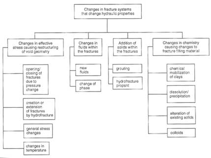
FIGURE 7.1 Changes to fracture systems that change hydraulic properties.
The fourth is a change in the distribution of solid materials in fractures through chemical reactions. Dissolved minerals can precipitate and seal fractures. Leaching fluids can dissolve fracture fillings or fracture walls. In the extreme, precipitates can completely till fractures and form mineral veins, or the rock can dissolve, leading to the development of karst. Most such changes are caused by natural processes, but induced pressure and temperature alterations can produce similar effects.
CHANGES IN FRACTURE VOID GEOMETRY DUE TO CHANGES IN EFFECTIVE STRESS
A variety of engineering activities cause fractured rocks to deform or fail. Changes in fluid pressures, the addition or redistribution of loads, or changes in temperature can lead to changes in the state of stress in the rock. The apertures of fractures depend critically on effective stresses acting normal to the fracture planes. The ability of a fracture to conduct fluid is extremely sensitive to the aperture.
Four kinds of deformation are discussed below: (1) opening or closing of the fracture owing to changes in fluid pressure, (2) the formation and extension of fractures in response to elevated fluid pressures, (3) deformation or failure of
fractures in response to general changes in stress state, and (4) deformation of fractures owing to heating or cooling.
Changes in Fracture Aperture Due to Fluid Pressure Changes
Fluid pressure in fractures can change during many common engineering activities when fluid is withdrawn from or injected into a fractured rock. For fluid injection or withdrawal in a well, radial symmetry results in large fluid pressure changes near the wellbore. For steady-state Darcy flow into or out of a well with a diameter of a few tens of centimeters, most of the pressure change occurs in the first few meters of rock surrounding the well. The flow gradients alter the stresses by changing the pore pressure and by viscous drag on the pore walls. The drag is analogous to a body force acting in the direction of flow. The field of poroelasticity deals with the relationship between pore fluids and matrix stresses. Perkins and Gonzales (1984) provide an example of the use of poroelastic principles for the analysis of stress changes around an injection well.
Any excavation in a rock mass under the groundwater table for tunnels, mines, or foundations tends to drain fluid from the rock. Fluid pressures decrease to near-atmospheric levels in the excavation, which increases the hydraulic gradient. Drainage causes a reduction in water pressure near the excavation. However, this effect can be counteracted by seepage stresses. Reduction of water pressure usually results in a strengthening of the rock mass because of the increase in effective stress. It is possible but rare that this reduction in water pressure can increase the effective stress sufficiently to cause failure and excavation collapse or borehole instability. At the same time, increases in water pressure can produce irreversible changes in fracture network properties, as described in the water well stimulation example illustrated in Appendix 4.C.
Effective Stress and Fluid Flow
Changes in fracture systems owing to variations in pore pressure can be understood by using the concept of effective stress, as discussed in Chapter 3. Fluid pressure in the pore spaces of rock (including the apertures of fractures) works against externally applied compressive stresses. For fractures the effective stress is the difference between the total stress applied on the fracture face and the pore pressure in the fracture (see Chapter 3). Stress-dependent properties such as frictional strength and fluid permeability are governed by the effective stress. An increase in effective stress will close the fractures and reduce their permeability; a decrease in effective stress will have the opposite effect.
A field example of the relationship between flow behavior and effective stress is given in Figure 7.2, for a fractured sandstone gas reservoir at the U.S. Department of Energy's multiwell site in western Colorado (Warpinski, 1991). The matrix permeability of the marine sandstone reservoirs is less that 10-18 m2
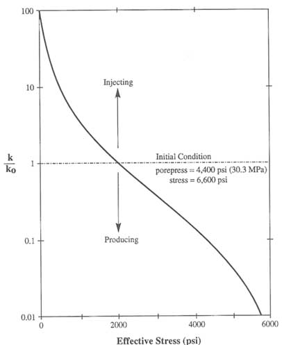
FIGURE 7.2 Permeability vs. stress as determined in the multiwell site. Modified from Warpinski (1991).
(less that one microdarcy; see Chapter 8). The minimum principal stress is normal to the dominant fracture orientation. The fracture network provides an overall in situ permeability that is several orders of magnitude greater than the matrix permeability and a horizontal permeability-anisotropy ratio of about 100:1 (inferred from interference testing with nearby wells). The stress-permeability relationship shown in Figure 7.2 is based on the model presented by Walsh (1981):
where k is permeability, ko is the reservoir permeability under in situ conditions, ![]() is the normal stress on the fracture,
is the normal stress on the fracture, ![]() * is the reference stress state, and C is a constant. The parameters C and
* is the reference stress state, and C is a constant. The parameters C and ![]() * were calibrated by using the results from two different stress conditions. The first was for a low effective stress [<6.89 MPa (<1000 psi)], achieved by injecting nitrogen. Under this condition, the effective reservoir permeability was found to be one to two orders of magnitude greater than that for initial reservoir conditions. The second was for high effective stress [>34.5 MPa (>5000 psi)], achieved by producing the well with a drawdown sufficient to stop all production (i.e., for k = 0). During multiple cycles of production, shutin, and injection, the permeability changes in this reservoir were found to be reversible, with no significant changes to the original permeability after reestablishment of the initial reservoir pressure (i.e., after a long shutin period).
* were calibrated by using the results from two different stress conditions. The first was for a low effective stress [<6.89 MPa (<1000 psi)], achieved by injecting nitrogen. Under this condition, the effective reservoir permeability was found to be one to two orders of magnitude greater than that for initial reservoir conditions. The second was for high effective stress [>34.5 MPa (>5000 psi)], achieved by producing the well with a drawdown sufficient to stop all production (i.e., for k = 0). During multiple cycles of production, shutin, and injection, the permeability changes in this reservoir were found to be reversible, with no significant changes to the original permeability after reestablishment of the initial reservoir pressure (i.e., after a long shutin period).
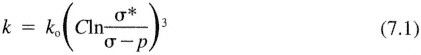
The impact of an increase in effective stress on reservoir performance is illustrated in Figure 7.3. This figure shows how the steady-state flow rate is related to steady-state drawdown for a rigid system (dashed line) and calculated for the compliant system (solid line) illustrated in Figure 7.2. In the rigid system, flow into the well is proportional to the drawdown. In the compliant system the increase in flow produced by increasing the drawdown, which increases the effective stress, is offset by the consequent decrease in fracture conductivity. For
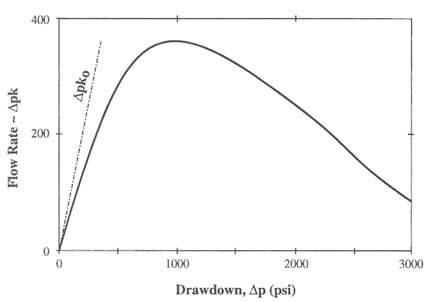
FIGURE 7.3 Change in steady-state flow rate as a function of drawdown based on the permeability reduction relationship given in Figure 7.2.
drawdowns somewhat greater than 6.89 MPa (<1000 psi), production can decline dramatically with increasing drawdown.
Effective Stress and Anisotropy
Changes in pore pressure can affect the degree of permeability anisotropy. For example, in cases with both significant matrix and fracture permeability where there is only one dominant fracture set, an increase in pore pressure will lower the effective stress. This leads to an increase in anisotropy by opening the fractures, thus increasing the permeability parallel to the fracture orientation. The permeability in other directions would be unchanged by comparison because it is controlled by the less stress-sensitive matrix.
Where there is more than one fracture set, the nature of anisotropy change would depend on which of the sets were more deformable. In the case of decreasing pore pressures in a low-permeability rock matrix, the closing of fractures could lead to a situation where the rock mass permeability is equal to the matrix permeability by reducing fracture interconnectivity below the critical limit for percolation (see Chapter 6).
In a poorly connected fracture network, a decrease in pore pressure could theoretically make the rock more isotropic. As some fractures become relatively impermeable, their connectivity is reduced to near the percolation limit. At the percolation limit, the flow in any direction must utilize fractures of all orientations. The flow observed on a large scale then depends on the same few open fractures, and permeability is consequently isotropic.
Determining Effective Stress
Determination of the stress field and pore pressure distributions are prerequisites to determining the effective stress. The state of stress is represented by a symmetric second-order tensor, so there will always exist three mutually perpendicular vectors that define the so-called principal stress directions. In general, the state of stress is anisotropic, and three principal values of stress and their directions are needed for a complete description. Generally, when the stress directions are not altered by nearby faults, the principal stresses are horizontal and vertical, with overburden pressure given by
where ![]() is the rock density, g is the gravitational acceleration, and z is the depth below the surface. For rock with shear strength in an extensional regime, the vertical stress is usually the major principal stress; the horizontal stresses take on a variety of values. For rock with shear strength in a compressional regime, the maximum principal stress can be horizontal, and the least principal stress can be vertical. Near the surface the maximum principal stress also can be
is the rock density, g is the gravitational acceleration, and z is the depth below the surface. For rock with shear strength in an extensional regime, the vertical stress is usually the major principal stress; the horizontal stresses take on a variety of values. For rock with shear strength in a compressional regime, the maximum principal stress can be horizontal, and the least principal stress can be vertical. Near the surface the maximum principal stress also can be
horizontal if the terrain is overconsolidated, that is, if some of the original overburden has been removed by erosion.
Measurement of the magnitude of the minimum principal stresses and their orientation by hydraulic fracturing is well established in the mining, petroleum, and geotechnical industries. Hydrofracturing is discussed more completely below. A number of other methods use measurements of strain to infer the state of stress.
The pore pressure frequently has a hydrostatic gradient, which is given by p = ![]() wgz*, where
wgz*, where ![]() w is is the density of water and z* is the depth below the water table. Under these conditions, the effective vertical stress,
w is is the density of water and z* is the depth below the water table. Under these conditions, the effective vertical stress, ![]() v, can easily be estimated [i.e.,
v, can easily be estimated [i.e., ![]() v =
v = ![]() - p = g z -
- p = g z - ![]() wz*)]. Both bulk deformation and fluid volume change in response to changes in pressure. When pressure changes in fractures, fluid diffuses at a rate that depends on the permeability distribution in the rock. For fractures in impermeable rock, the matrix has no effect on pressure change. Thus, a change in fluid pressure in the fractures will result in a proportional change in the effective stress acting on the fractures. However, for fractures in a permeable matrix, fluid will diffuse into or out of the surrounding rock, and, consequently, the pressure change introduced into the fractures will be damped. Engelder (1993) gives a recent summary of stress regimes in the lithosphere.
wz*)]. Both bulk deformation and fluid volume change in response to changes in pressure. When pressure changes in fractures, fluid diffuses at a rate that depends on the permeability distribution in the rock. For fractures in impermeable rock, the matrix has no effect on pressure change. Thus, a change in fluid pressure in the fractures will result in a proportional change in the effective stress acting on the fractures. However, for fractures in a permeable matrix, fluid will diffuse into or out of the surrounding rock, and, consequently, the pressure change introduced into the fractures will be damped. Engelder (1993) gives a recent summary of stress regimes in the lithosphere.
Hydraulic flow models (Chapter 6) are often used to quantify the fluid pressure distribution in places where there are no measurements. Quasi-continuum models or closed form solutions can be used to calculate fluid pressures. To use these models, it is necessary to relate an equivalent quasi-continuum conductivity to the rock mass, either through single- or double-porosity models (see Chapter 6). Most discrete network models such as those described in Chapter 6 are applicable, but the limited knowledge of fracture geometry and fracture flow characteristics in most engineering problems makes their use unlikely. Further, variability in pressure is much smaller than variability in flow. Hence, less sophisticated models may be adequate.
Predicting the Behavior of Stress-Sensitive Flow
Modeling of subsurface flow is usually conducted under the assumption that permeability is independent of the state of stress. Some work has been done, however, on flow through so-called pressure-sensitive media. Because the permeability of fractures usually exhibits some dependence on stress, these models should be applicable to fractured rock masses. One of the earliest treatments of this problem was by Raghavan et al. (1972), who developed type curves for flow in a bounded circular reservoir whose permeability and porosity varied with the pore fluid pressure. Wall et al. (1991) present drawdown curves and pressure profiles for slug tests in pressure-sensitive formations. Dvorkin and Nur (1992) present an approximate analytical solution for a one-dimensional filtration front invading a formation whose permeability changes from zero to ko as the pressure
changes from p < pc to p > pc, where pc is some critical pressure at which an interconnected network of fractures is formed.
In some cases the flow system influences the effective stress enough to significantly change the permeability of the flow system. In these cases it may be necessary to use a coupled stress-flow model to understand the behavior of the fracture flow system. Several coupled models are available (Noorishad et al., 1971, 1982, 1992; Kafritsas, 1987). The hydrogeological simulation models that have been linked to mechanical deformation models originated primarily in geotechnical engineering fields.
Coupled models account for the role of deformation in fluid flow and the stability of the rock mass. Flow is linked to deformation through changes in permeability and storage. Deformation is linked to flow through changes in fluid pressure, which results in changes in effective stress. A critical element in these models is representation of the proper hydrological and material constitutive behaviors for the fracture and solid rock. Models based on a discrete representation of the fracture network assign separate values to the fracture and block stiffnesses.
Fluid flow is also modeled on a fracture-by-fracture basis (e.g., Asgian, 1989). These hydromechanical models have been used to examine the coupling between fluid pressure responses and deformation for idealized settings. Representation of the fractured material in the mechanical model is more complex than the representations described in Chapter 6 for fluid flow. Just as for fluid flow, if the rock is highly fractured and the fractures have a wide range of orientations, it may be possible to use continuum deterministic or stochastic deformation techniques. For heterogeneous fracturing, additional complexity must be built into the model. For example, rock with a series of parallel fractures may be represented as a laminated material. Methods for coupled modeling of flow and deformation have been evaluated by DECOVALEX (1991).
Discrete-element models have been used for coupled fracture flow and deformation problems, such as flow under a dam, rock slope behavior, and flow to or from a well (Noorishad et al., 1971; Kafritsas, 1987). Figure 7.4 provides examples of models of this type. A well is located at the center of a rectangular domain, which contains a much simplified fracture network. The diagram on the left illustrates the computed deformation of the rock mass that occurs with fluid injection. The diagram on the right illustrates the nature of deformation if water is withdrawn from the rock mass through the well.
Assessment of Models of Stress-Sensitive Fluid Flow
In general, the principles governing the relationship between pressure changes and fluid flow are well understood. However, prediction of this behavior through the use of models is problematic. There are few experiments available at field scales that can be used to test these models. The problems are similar to those encountered in defining fracture flow systems (see Chapter 6). There are difficulties
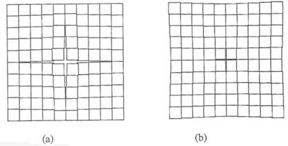
FIGURE 7.4 Deformation computed by a coupled flow and deformation analysis for a well under (a) injection and (b) withdrawal. Computations performed with the Massachusetts Institute of Technology discrete element model. From Kafritsas (1987).
in scaling up point measurements to obtain values that apply to field-scale behavior. There are considerable amounts of laboratory data that establish constitutive relationships between effective stress and fracture permeability for single fractures in rock cores (see Chapter 3), but field-based data are few in number. Boundary conditions are often unknown, yet they may control flow and stress behavior.
In attempting to fit hydromechanical models to data sets involving single-borehole deformation experiments, it has been observed that there are problems in identifying unique sets of parameters to characterize field responses. Some success has been achieved in duplicating single-fracture experiments (Rutqvist et al., 1992). However, because of the multitude of parameters that determine the nonlinear hydromechanical response of a rock mass containing a network of fractures, site-specific predictive simulation is extremely difficult.
The practical significance of stress-sensitive fluid flow in fractured rock needs to be evaluated for a range of field-scale problems. This can be accomplished by using numerical simulation models that account for stress-dependent flow.
Creation or Extension of Fractures Due to Increases in Fluid Pressures
Hydrofracture is the extensional failure of rock that takes place when fluid pressure increases to the point that effective stresses become negative and exceed the tensile strength of the rock. Hydraulic fracturing occurs intentionally or unintentionally during many activities that provide sources of fluids at high pressures. For fractures to propagate, the fluid must be supplied in sufficient amounts to ''fill" the growing volume of opening fractures. There is an extensive literature available on hydrofracture, and only a brief description is given here.
Hydrofracture is used as a stress measurement tool (e.g., Engelder, 1993). In this application a hydrofracture is created in a section of borehole isolated with packers. The pressure in the interval is increased until the borehole ruptures, resulting in the formation of new fractures or the extension of old ones, which causes a sudden decline in pressure. The pressure required to maintain the fracture openings is assumed to be equal to the minimum principal stress. A slightly higher pressure will extend the fracture. (Once it has closed, the pressure required to reopen it can be significantly higher.) For homogeneous isotropic formations, hydrofractures grow in a direction perpendicular to the minimum principal stress.
Hydraulic fracturing is also used to increase conductivities around production wells. A decline in permeability can arise from high effective stresses at the borehole, owing to: (1) stress concentrations around the borehole (which depend on the original stress field) or (2) large pressure drops around the borehole owing to radial flow. A newly formed hydrofracture can increase the conductivity near the well and consequently increase the effective wellbore radius by as much as one-half the fracture penetration (Prats, 1961). Hydraulic fracturing is a common practice in wells used for resource recovery. Typical penetrations (i.e., the propped lengths of the hydrofractures) are greater than 200 m, producing an effective well radius of more than 100 m. Fracturing is a very practical means to achieve a large effective wellbore radius at significant depths.
Hydrofracture can also occur, unintentionally, during injection of fluids. In these cases, studies can be designed to find safe injection pressures that will not cause fractures to open and extend. Control of fracturing during "flooding" operations has been a long-term concern of the petroleum industry. Flooding includes water injection for "secondary recovery" and chemical injection for "tertiary recovery" (e.g., Lake, 1989). The objective of flooding is to provide an effective sweep of the reservoir with the injected fluids. This is achieved by controlling the extent to which hydraulic fractures propagate from the injection well toward a production well in order to prevent a ''short-circuit" in the flow pattern of the injected fluid. Mud pressure during drilling can either open or create new fractures. This phenomenon can lead to lost circulation (too little drilling fluid returning to the surface) and, in the extreme, to loss of the hole owing to rock failure and stuck tools.
The control of hydraulic fracturing is also important for waste disposal wells, and much of the petroleum industry's experience and technology are directly applicable. Over time, injection wells are subjected to the cumulative effects of particulates and other contaminants in the injected fluids, which decrease permeabilities. The maintenance of nominal injection rates requires increasing the injection pressure. Eventually, the elevated injection pressures will cause the extension of fractures that create new injection areas beyond the region of significant permeability impairment. Alternatively, the permeability decrease can be ameliorated by chemical treatment (e.g., Economides and Nolte, 1989).
A dam supporting a filled reservoir has large pore and joint water pressure gradients in its abutments and foundations. Such high pressures can reduce the strength of the rock mass and can cause movement of rock blocks, with potentially catastrophic consequences. The pressures can also open fractures and allow significant amounts of fluid to flow around or under the dam. Large pore pressures under the toe or downstream of a dam, in combination with the large shear stresses, can produce foundation failures. Entirely analogous but more serious conditions exist in the dam abutment slopes because the water pressure produces both high pore pressures and high hydraulic thrusts. The 1959 Malpasset Dam failure is an example of such a failure (Londe, 1987).
A related problem is that of reservoir-induced earthquakes or similar seismic events. High water loads and pore pressures can induce slippage along fractures. Earthquakes of magnitudes up to 6.5 have occurred, owing to either injection or withdrawal of fluids (Meade, 1991). Studies indicate that the level of induced seismicity depends strongly on preexisting stress conditions in the upper crust.
Fracture Initiation and Growth
A fracture is initiated when the fluid pressure exceeds the total stress plus the tensile strength of the rock, as discussed earlier. Stress heterogeneity plays a role because it is the total local stress that must be exceeded in order to initiate a fracture. For example, total stress near a well may be elevated above the far-field stress by stress concentrations around the wellbore. If fractures are present, the pressure required to open them is equal to the compressive stresses across the fractures.
The stress intensity factor at the tips of the fractures must exceed a critical value in order for the fractures to be extended. The stress intensity factor is a function of the fluid pressure in the crack and the crack geometry, as described in Chapter 2.
The fracture growth process is governed by the coupling between fracture deformation, fluid flow, and the mechanical properties and stresses in the matrix. For spatially constant properties and stresses, the pressure required to propagate the fracture decreases as the fracture gets longer, because the greater length of the fracture provides greater leverage on the tip (Economides and Nolte, 1989).
Stress variations between different sedimentary layers can enhance lateral fracture extension relative to vertical fracture extension. Such stress variations can produce elongated fractures that will propagate only by increasing pressure (Teufel, 1979). This is a common occurrence for hydraulic fracturing in petroleum reservoirs, as illustrated in Figure 7.5. The figure indicates generally increasing pressure during the injection phase (denoted as "fracture treatment" in the figure). The interval after injection is divided into two time periods. During the first period of "fracture closing," the fluid pressure and fracture aperture decrease as fluid in the fracture infiltrates the surrounding rock (Warpinski, 1985). The period
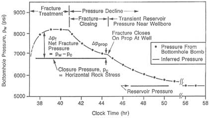
FIGURE 7.5 Example of bottomhole pressure in a well during a hydrofracture operation. After Nolte (1982).
Much is known about hydrofracturing from an engineering perspective (e.g., Gidley et al., 1989), but there are still uncertainties about details of the physical processes. The behavior of hydrofracture in some rock types is not well understood. The effect of heterogeneities (e.g., existing fractures) on hydrofracture geometry also is not well understood (Warpinski and Teufel, 1987).
As a flow rate enhancing tool, hydrofracture may fail if matrix permeability is small and existing fracture orientations are parallel to the current maximum horizontal stress. For this case, the induced fractures will follow the same orientation as the existing fractures, providing little additional connectivity between fractures. To some extent, this problem has been overcome in the petroleum industry with drilling technology that allows wells to be oriented in any direction. Such wells can be drilled normal to the fractures in order to connect them. In a massively fractured formation, hydrofracture can be used to connect the well to a highly productive part of the fracture network.
Stress Sensitivity Tests
The determination of a safe injection pressure can be obtained from a "step-rate" test to infer the conditions to extend a fracture, that is, the "extension
pressure." This test is conducted with a progression of injection flow rates, Q, with each rate generally maintained to reach steady conditions. For each rate the final pressure increase, ΔP, relative to in situ pore pressure, is plotted versus the flow rate, Q. This plot, illustrated on the right side of Figure 7.6, exhibits a characteristic "dogleg" where hydraulic fracturing begins. The dogleg occurs at the extension pressure where the resistance to injection, ΔP/Q, decreases as additional formation area is exposed via an extending fracture, that is, an extending effective well radius.
After prolonged injection, the pore pressure in the formation will change, as will the temperature, if the temperature of the injected fluid is different from the formation temperature (the temperature can either increase or decrease). Consequently, the pressure required to extend the hydrofractures will change with time. Therefore, it is good practice to periodically conduct step-rate tests to rede-line safe injection pressures.
Another way to diagnose and quantify stress sensitivity is to perform several flow or injection tests at substantially different flow rates, Q (as used to obtain the relationship in Figure 7.2), followed by sufficient shut-in periods to perform valid buildup or fall-off analyses. The amount of variation in the values of Q/ΔP at steady-state for the various tests will indicate the degree of stress-sensitive behavior. If there is no variation in Q/ΔP, the system is rigid. If variation is observed, the data can be used to develop a relationship between pressure and permeability, such as that shown in Figure 7.2. Furthermore, the effects of "skin" (altered near-well permeability) will be evident from the buildup or fall-off analyses, with the far-field (i.e., initial, in situ) permeability reflected by the late-time data. These data provide the required information to diagnose and quantify the stress permeability conditions of the system.
In some cases it is possible to place a strain gauge across a fracture in a borehole. The displacement of the fracture can then be measured as the pressure in the borehole interval is changed. Such measurements using a BoFex strain gauge have been made in the Underground Research Laboratory in Canada
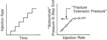
FIGURE 7.6 Step-rate test to determine stress sensitivity of fractured rock. Nolte (1982).
(Martin et al., 1990) and at the Grimsel test facility in Switzerland (Majer et al., 1990; see Chapter 8).
Monitoring of Fracture Location
The extent and orientation of hydraulic fractures created by injecting fluid into a well can be mapped by the resulting seismic activity (Chapter 4). This activity is induced by the infiltration of fluid into a natural fracture network at high pressures, which induces slip. These slippages release seismic energy. The release point can be triangulated in much the same way that an earthquake epicenter is located.
Extremely sensitive tiltmeters can be placed on the surface of the ground to monitor hydrofracturing. These meters can be used to determine the direction and volume of the fractures. Available instruments can measure tilts in the nano-radian range. Strain caused by massive hydrofracture creation at depths of thousands of meters can be detected at the surface with these instruments. See Chapter 4 for a more complete description of tiltmeter technology.
Fracture Propagation Models
Hydraulic fractures were originally modeled as two-dimensional features with constant height. Several types of two-dimensional models were assembled by using analytical solutions (e.g., Khristianovich and Zheltov, 1955; Perkins and Kern, 1961; Geertsma and de Klerk, 1969). More sophisticated pseudo-three-dimensional models have recently been developed to calculate fracture height in layered reservoirs (Nolte, 1982; Settari and Cleary, 1984; Meyer, 1989). The term pseudo-three-dimensional (or P3D) is commonly used to describe computationally efficient algorithms the provide some of the desired features of three-dimensional models (e.g., extension and fluid flow in both directions of the vertical fracture plane). However, the desired efficiency of the P3D models is achieved by varying the degrees of constraint on fracture shape and fluid flow or by relaxing the lateral extent of elastic coupling along the fracture plane. One P3D class contains the "lumped-parameter" models and is most applicable to fractures with similar dimensions in all directions of the fracture plane. This shape occurs for formations that are either homogeneous or composed of layers with similar stresses and mechanical properties over the extent of the fracture. The "lumped" models generally constrain the fracture plane and flow field to elliptical shapes and determine the fracture dimensions by parameters averaged over the fracture plane (i.e., lumped parameters). The other popular P3D class contains the "cellular'' models and is most applicable to fractures that have a large aspect ratio. This shape occurs for sedimentary sequences that have significant horizontal stress contrasts between the horizontal layers. The higher stress layers limit vertical extension and enhance the desired lateral extension into the petro-
leum reservoir. The "cellular" models generally consider fluid pressure gradients only in the long (i.e., lateral) direction and ignore lateral elastic coupling between cells for determining the fracture aperture and vertical height (i.e., the height and aperture for a cell depend only on the fluid pressure in that cell). When conditions do not favor the assumptions for P3D models, fully three-dimensional models using boundary-element and finite-element formulations also are being applied (Clifton and Wang, 1988; Advani et al., 1990). Oil companies predominantly use two-dimensional and P3D codes for fracture design. Warpinski et al. (1994) provide a comparison of results for some of these codes.
Coupled flow and deformation models can be used to model hydrofractures if their propagation directions are known or can be assumed. For the fully three-dimensional and differenced P3D forms, a series of elements in the model are lined up in the direction of the fracture. Elements are either added (fixed mesh) or stretched (moving mesh) as the fracture extends. For the fixed mesh case, as each element is judged to have opened based on the critical stress concentration, the mechanical and hydrological properties of the element are changed from that of rock to that of fracture. Thus, the fracture can be considered to develop in discrete intervals (Rutqvist et al., 1992). Lumped-parameter or integrated models use global parameters, which reflect some averaged properties of the fractures, that are changed as the rock fails.
A new series of models based on boundary elements allow calculation of stress concentrations, including the effects of other fractures. These models calculate the direction and location of fractures that result from the change in loading (Olson, 1990).
The propagation of natural fractures in the earth's crust is discussed in Appendix 7.A.
Deformation or Failure Owing to General Changes in the State of Stress
Previous sections addressed the opening and closing of fractures owing to changes in pore pressure. This section highlights changes to fracture systems (opening, closing, or shear) that are caused by loading factors that affect or are affected by fluid flow. Such loads can occur in slopes, underground openings, reservoirs, or dam foundations.
There are several modes of slope failure, depending on slope material, orientation and type of jointing, and overall geological structure of the formation. In all cases, hydraulic pressure from groundwater is a substantial threat to slope stability. The pressure of groundwater reduces effective stress, as noted previously, which decreases the shearing resistance. Groundwater pressure can also generate a significant force acting toward the slope face that can promote instability. In designing slopes it is essential to consider hydraulic conditions because they determine stable slope geometries. For any specified slope height, the allowable slope angle is a strong function of the degree of saturation (Hoek and Bray,
1981). In some applications there may be a strong economic incentive to achieve high slope angles. For example, in open-pit mining, steep angles minimize the amount of waste rock that must be mined. In such cases, actions can be taken to maintain dry conditions. Options include the drainage measures discussed in Appendix 7.B and reinforcement of the rock mass through bolting or external supports.
Fractures around underground openings represent surfaces of weakness that are potential sources of failure. Significant changes in stress occur around cavities, which usually make instability more likely. In addition, stress effects can play a major role in altering the fracture flow and fluid pressure, which in turn affects the stability of the opening.
Pore pressure reductions caused by fluid production in reservoirs are usually thought to result in subsidence and reduced permeability, as discussed previously. However, in some cases there can be significant subsidence without an associated decline in permeability. Teufel et al. (1991) examined such a case for the Ekofisk field in the North Sea and postulated that the change in stress state could induce the creation of new fractures that offset the permeability decline. This behavior depends on the boundary conditions and Poisson effects in the reservoir.
Changes in fracture systems caused by pore pressure changes associated with dams and reservoirs were discussed previously. A crucial aspect of dam foundation and abutment behavior is the combination of large loads and pore pressures and the abrupt changes in loads and pressures that occur over relatively short distances. The reservoir thrust acts to push the dam downstream and close downstream fractures, which may lead to a pressure buildup near the toe of the dam. This thrust often opens fractures at the upstream (heel) side of the dam, which further promotes pressure increases. The large pore pressures (Figure 7.7) under the toe of the dam or downstream of it, in combination with the large shear stresses acting there, can produce foundation failure. Entirely analogous conditions exist in the dam abutment slopes.
Stress Distribution and Stress-Permeability Relationships
As discussed in Chapter 3, stresses acting on fractures are perturbed by the fractures themselves. Consequently, local stress changes may not be equal to far-field stress changes. Changes in normal stress on the fractures are equivalent to the changes in effective stress (discussed above) for pore pressure changes. Changes in normal stress will cause fractures to open or close, which will change their permeabilities. Changes in shear stress will have little effect unless the fractures displace in shear or fail. Effective stress plays a role in shear because shear strength decreases with decreases in effective stress. The relationship between shear, fracture geometry, and permeability is discussed in Chapter 3. The difference between shear deformation and normal deformation with respect to permeability change is that shear strain can either increase or decrease perme-
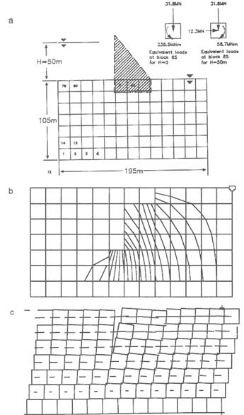
FIGURE 7.7 Flow nets and deformation in fractured rock under a dam. (a) distinct element model; (b) pseudoequipotentials with grout curtain to 60 m below dam foundation; and (c) displacements (magnified) due to dam load and reservoir water pressure. (The term pseudoequipotentials is used because the equipotential lines shown here are those seen in a continuum, while the numerical approach used to calculate them is based on discrete elements.) From Kafritsas (1987).
ability. Theoretically, shear can also increase the anisotropy of permeability in the plane of the fracture by creating both channels and barriers perpendicular to the direction of shear.
Modeling Deformation and Failure
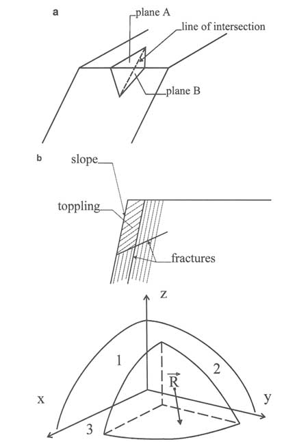
Deformation and failure of fractured rock masses can be modeled in three ways: (1) individual block analyses, (2) multiple block analyses, and (3) quasicontinuum analyses. The most common stability analysis methods are rigid-body analyses of individual blocks or wedges. Graphical (e.g., Goodman, 1976) or vector analytical methods (see Wittke, 1965; Hendron et al., 1971; Einstein et al., 1979) are used to determine whether the block or wedge is kinematically unstable and what kind of movement the block or wedge may undergo. Typical movement is translational sliding along one or more (usually two) planes (Figure 7.8a).
Sliding combined with rotation on planes also is possible, as is rotation around edges or corners; the latter movement is called toppling (Figure 7.8b). The vector analytical determination of kinematic instability consists of comparing the resulting driving force and moment to given directions that characterize particular movements. For instance, for movements on a single plane, the driving force must point into this plane and away from other boundary planes (see Figure 7.8c). Other kinematic considerations include the relative inclination of the sliding planes and the slope and various conditions of toppling. A good summary of these conditions is given by Goodman (1976).
Once the kinematic instability and type of movement have been determined, the kinetic stability is analyzed by comparing all driving and resisting forces using limit equilibrium analysis. Driving forces such as gravity, water pressures, and dynamic forces (e.g., earthquakes) are compared to resisting forces, including cohesive- or friction-related forces and artificial stabilizing forces such as bolts or tiebacks. Limit equilibrium analysis, by definition, assumes rigid-body conditions, that is, no deformation and no stress distributions. Some force comparisons require consideration of the size of the block or plane under consideration (e.g., cohesive forces and water pressure), whereas others do not (e.g., weight/friction).
Deformation or Failure of Fractures Owing to Heating or Cooling of the Rock
Significant changes in rock temperature can occur at the earth's surface under natural weather changes or in a nuclear waste repository, a geothermal reservoir, a flooded petroleum reservoir, or an excavation. Natural weather conditions include freezing temperatures that create ice in fractures. Expanding ice extends fractures, and ice can block water flow from fractures, producing pressure buildups.
Nuclear waste stored underground can provide a significant source of heat. Temperature changes in underground repositories can be affected by several
factors, including the age of the waste before emplacement and the density of waste storage. Repository temperatures over 100°C will create a significantly different environment than temperatures below 100°C because of boiling and steam production (Wang et al., 1981).
Geothermal reservoirs provide many opportunities to observe the effects of temperature changes on fracture systems. As geothermal wells are pumped, they draw heated fluids up from the deeper portions of the reservoir. These fluids heat rocks in the upper part of the reservoir, causing them to expand, which closes fractures and increases fluid pressures. Reinjection of cold fluids cools the rock and may lower fluid pressures.
Prior to 1980, most petroleum flooding projects were in reservoirs with in situ temperatures approximately equal to that of the injected fluids. For these cases, only poroelastic effects were significant, and flooding produced generally increasing pressures. More recently, flooding operations have been undertaken in deeper formations in Alaska and the North Sea, where relatively cool seawater is injected into higher-temperature formations. This can result in undesired hydrofracture owing to thermoelastic effects (e.g., Williams et al., 1989).
Temperature changes can have a significant effect on stresses around a cylindrical cavity such as a wellbore; for example, for rock with typical physical properties, hoop stress can change by 0.1 to 1 MPa/°C (1 to 10 bars/°C), with the precise value primarily dependent on the elastic modulus (Stephens and Voight, 1982). A 20°C decrease in temperature at the cavity face can reduce the total and effective stresses by 2 to 20 MPa (20 to 200 bars) and offset the stress concentration from the far-field stress, with a potential impact on stability. Such reductions in effective stress can be important at the very cold temperatures encountered in underground gas storage. A 20°C increase in temperature can provide an effective stress increase of 2 to 20 MPa (20 to 200 bars), which can lead to local reductions in fracture permeability.
Thermoelasticity and Flow
Thermoelasticity relates the change in temperature to stress through an understanding of thermal expansion coefficients and stress-strain constitutive relationships. Both rock and fluid expand when heated. If expansion is resisted, thermal stresses are created. The amount of thermal stress produced by a change in temperature depends both on the temperature increase and the boundary conditions. For example, if fluid in a rock is heated, its expansion will have little effect on stress if the fluid is unconfined because the resulting fluid pressure can be dissipated. Heating of confined fluids, on the other hand, can increase pore pressures significantly, even to the point of extending fractures. The induced stresses in a confined heated body are roughly on the order of E![]() ΔT, where E is Young's modulus,
ΔT, where E is Young's modulus, ![]() is the thermal expansion coefficient, and ΔT is temperature rise (measured from some reference temperature). The standard treatise on thermal stresses is Boley and Weiner's (1960) text.
is the thermal expansion coefficient, and ΔT is temperature rise (measured from some reference temperature). The standard treatise on thermal stresses is Boley and Weiner's (1960) text.
A good conceptual model for understanding the effects of temperature on fractured rock is to think of the rock blocks as very stiff compared to the more compliant fractures. As a rock is heated, the blocks expand into the fracture voids. Heating the fluid in the fractures at the same time will cause a net decrease in effective stress as the fluid expands. However, unless the fluid is confined, fluid expansion will be less significant than rock expansion. Consequently, an increase in temperature has the same effect on fractures as an increase in effective stress.
Rapid heating or cooling can lead to failure owing to differential expansion of adjacent rock grains (Stephens and Voight, 1982). Even slow heating can cause extensional regions to form, depending on geometry and boundary conditions (Fredrick and Wong, 1986). Prolonged injection of relatively hot fluids will increase stresses and result in loss of permeability for natural fractures.
Injecting relatively cool fluid (compared to in situ temperatures) can induce a significant reduction in stress by thermoelastic behavior. In the extreme this can lead to a negative effective stress condition and hydraulic fracturing. Consequently, cold water injection results in reduced extension pressures from thermoelastic effects (e.g., Perkins and Gonzalez, 1984, 1985; Williams et al., 1989). When thermal effects are dominant, stresses in the injection zone will decrease, resulting in increased stress contrast between vertical layers. This will retard fracture propagation through the cap rock.
Changes in temperature cause changes in density and viscosity of fluids. In general, both density and viscosity of liquids decrease with increasing temperature; for gases an increase in temperature typically causes a decrease in density but an increase in viscosity. These changes, in turn, cause changes in the flow field.
Coupled Heat, Flow, and Stress Models
One modeling approach for heat and flow problems is to use a thermoelastic continuum model to calculate changes in stress owing to heat conduction alone. These models ignore heat transport by advection of fluids in fractures. Then the stresses are fed into coupled stress-flow models as described above. This approach is inadequate in fractured media if fluid velocities are high enough to result in significant heat transport by advection. Convection cells will form if the Raleigh number, which measures the relative strengths of advective and conductive heat transfer rates, exceeds some critical value (Phillips, 1991).
A more complete approach to the problem is to solve three coupled equations: one each for stress, temperature, and flow. This approach has been applied to the problem of heat production in a nuclear waste repository (Noorishad et al., 1984, 1992), where it was found that extensive regions of increased permeability owing to extension can be formed in rock above the repository.
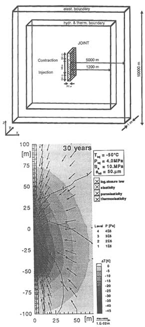
Kohl et al. (1996) have examined thermoelastic effects that impact the long-term performance of a hot dry rock geothermal system. Extraction of heat from
the subsurface, which typically involves circulating initially cold water through either a natural or an induced fracture network, causes significant stress changes in the rock mass. These stress changes, which are caused by pore pressure changes and thermal shrinkage as heat is extracted, can substantially alter the hydraulic properties of the rock mass.
Figure 7.9 shows a hot dry rock system in its simplest form, a single open fracture embedded in a less permeable rock matrix. Also shown in the figure are the calculated temperature change, fluid pressure, and rock mass displacement 30 years after the system has been in operation. Deformation of fractures owing to thermoelastic effects gives rise to increases in hydraulic apertures that increase flow through the fractures by 25 percent over the 30-year production period. Although the example is very simple, it is representative of the state of the art in modeling the long-term performance of such systems.
The principles governing rock behavior under changes in temperature are fairly well understood (Biot, 1956). However, the effect of heterogeneities and the coupling of temperature with fluid flow can make the consequences of temperature changes very difficult to predict. There is a need for careful laboratory and controlled field experiments in well-characterized fractured rock masses to determine the phenomena that dominate behavior.
CHANGES IN FRACTURE FLUIDS
Many engineering operations lead to changes in the fluids contained in fractures. These include changes in fluid phase or composition or redistribution of phases or components in the rock. The principles governing multiphase flow in fractures were discussed in Chapters 3 and 6 (see also de Marsily, 1987, p. 26). This section gives some examples of these changes, expanding on the discussion in Chapter 6, and addresses the principles that govern such behavior.
Changes in Fluid Phase
When a fracture system is subjected to changes in temperature or pressure, fluids may undergo a change of phase (i.e., from liquid to vapor). An increase in pressure may cause gas to be dissolved in the liquid phase, and, conversely, dissolved gas may evolve from the liquid phase when pressure declines. Chemical or microbiological reactions may also produce gas. Heat can cause vaporization, and cooling can cause condensation.
Dissolved gases can be released from solution as fluid pressure is lowered. This phenomenon occurs in oil wells, where gas comes out of solution as the oil flows toward a well and is pumped upward in the well toward the surface. In some gas reservoirs, pressure declines cause water to enter fractures from the matrix, thus creating a gas/water flow system and reducing the production of gas. Geothermal reservoirs can undergo dramatic phase changes as fluids are
produced or injected. These changes may be coupled to chemical changes, as described later in this chapter.
Gas can also evolve from fluids during flow into underground structures. Nitrogen from solution has been hypothesized to explain the dramatic decrease in permeability around a drift in the Stripa mine in Sweden (Long et al., 1992). In this case, inflow to six parallel boreholes was measured when the water pressure head in the holes was held at 17 m above atmospheric. A drift was excavated through the boreholes, but inflow to the drift was almost an order of magnitude lower than that extrapolated from the borehole data. The gas content of the water was about 6 percent nitrogen, and gas bubbles were observed in the outflow. Calculations of stress changes failed to account for this dramatic decrease in flow. One explanation is that two-phase flow conditions decreased the inflow.
The performance of nuclear waste repositories may be affected by phase changes in the fluids of surrounding rock. The repositories can produce significant quantities of heat, which can cause boiling, vapor flow, and condensation. These phase changes may be coupled to other mechanical and chemical changes, as discussed previously. These phenomena are not well understood, particularly for repositories constructed in unsaturated rock. In this case, two types of behavior may occur. The first is called the hot dry scenario, where heat from the repository drives all moisture away. The other is the heat pipe scenario, where steam is generated and flows upward, where it condenses and flows back to the repository as liquid water under gravity (Doughty and Pruess, 1988). In both cases, heat drives moisture away from the repository and gravity causes downward flow of condensate, which will be reheated and revaporized. The unresolved question is whether downward flow will reach the heat sources (waste packages) or whether there is a superheated region whose upper boundary moves upward some finite distance for significant periods of time. This question cannot be resolved without laboratory and in situ field experiments.
Principles Governing Phase Changes
At any given pressure, there is a maximum amount of gas that can be dissolved in the liquid phase of water. When the concentration of gas is small, a linear relationship exists between the maximum concentration of dissolved gas in the water and the partial pressure of gas in the vapor phase. The constant of proportionality, which depends on the species of gas, is known as Henry's law constant.
The general principles for understanding phase changes and the transfer of mass among phases are the province of chemical thermodynamics. For homogeneous systems in which no chemical reactions occur and external potentials (e.g., gravitational and electrical fields) can be ignored, the thermodynamic state can be specified completely by fixing temperature, pressure, and the number of moles of each component.
The conditions for equilibrium are that the temperature, pressure, and chemical potential of each substance are the same in all phases. The chemical potential is equal to the partial molar Gibbs free energy. All of these quantities are intensive variables; that is, they are independent of the total mass (or number of moles) present in the system and are completely determined by specifying temperature, pressure, and composition (e.g., the independent mole fractions of the components) of the phase. The principles governing phase equilibria are well understood, and methods exist for calculating phase properties even for complex multicomponent hydrocarbon mixtures. However, the complexity of the calculations increases rapidly with the number of fluid phases, especially if different parts of the system are not in equilibrium. Disequilibrium may be common in fractured rock because of the large differences in permeability between fractures and the pores in the matrix.
Changes in Fluid Interfaces
Injection or infiltration of miscible and immiscible fluids creates a multicomponent flow system in fractures. An example is contamination of groundwater with nonaqueous-phase liquids, a common problem for both porous and fractured media.
Dynamic large-scale movement of fluid interfaces can occur because of buoyancy effects, which can arise from density differences owing to temperature or compositional changes. For example, gas or water coning in petroleum reservoirs can be exacerbated by natural fractures that enhance vertical permeability. Mobile water, when present, will reside below the petroleum phase because water is more dense. Vertical flow and subsequent production of water is referred to as water coning. Coning begins as a change in the position of the interface between the water and petroleum phases. The boundary change for the dual-density system occurs to equilibrate the pressure gradient caused by producing the petroleum phase.
Water cones upward and gas cones downward. In a gas reservoir, water coning is undesirable and occurs when gas is produced at too high a rate. In an oil reservoir, it usually is not desirable to produce gas because gas production reduces drive energy and, consequently, the ultimate volume of oil recovered.
Water breakthrough by coning has at least three undesirable effects: (1) water is produced in the well and must be disposed of in an environmentally safe manner, (2) the flow height for the petroleum phase in the reservoir is restricted, and (3) the production rate is reduced because of the reduced drawdown at the bottom of the well. A reduced drawdown occurs because of the increase in hydrostatic head of the heavier produced fluids containing the denser water phase. Water coning has had a negative impact on production in many prolific fractured reservoirs. A completely effective countermeasure remains to be developed.
Coning is significant in gas reservoirs because there is a large density difference between gas and water. This difference provides a larger hydrostatic head difference between the water and the well compared to the gas and the well. No gas production can be obtained until the water is pumped off. Pumping is also used in more conventional reservoirs with high water saturations. In either case, fractures may provide the pathways between the two phases and complicate the control of coning.
Saltwater intrusion into coastal aquifers produces large-scale changes in fluid-phase interfaces. Such intrusion is promoted by overpumping fresh water that overlies saltwater. In fracture systems the boundary between fresh water and saltwater can be very complex because it is partly controlled by the connectivity of the fracture system. As measured from the surface, the depth to the interface can vary, depending on which fractures are intersected and how well they are connected to the pumping wells.
The location of an interface is determined by a balance of gravitational and viscous forces. Capillary forces may play a role if more than one phase is present. Gravitational effects arise from differences in fluid density. These density differences may be related to variations in fluid composition, temperature, pressure, or concentration. For example, the change in location of an interface, Δh, after a change in pressure, ΔP, is given by
where ∆![]() is the difference in density between the two fluids. In a fracture network each fracture may have a different ΔP, and therefore a different Δh. Thus, the elevation of the interface may vary significantly from fracture to fracture.
is the difference in density between the two fluids. In a fracture network each fracture may have a different ΔP, and therefore a different Δh. Thus, the elevation of the interface may vary significantly from fracture to fracture.
If the three-dimensional fracture geometry is known, the location of an interface under a given flow regime can be calculated. The problem in calculating interface movement is at least as complicated as that of defining the fracture flow system, as described in Chapter 6.
ADDITION OF SOLIDS
Suspended solids or liquids that solidify may be added to a system deliberately—for grouting or propping of hydraulically induced fractures—or inadvertently during injection of water for aquifer recharge, aqueous waste disposal, well drilling and completion, and water flooding. The introduction of solids into a fractured rock mass will usually decrease its bulk permeability. This permeability decrease is one of the desired results for grouting but is generally undesirable in cases of inadvertent injection of suspended solids.
Proppant
Coarse-grained proppants are suspended in a carrier fluid during hydrofracturing to prevent closure of the fractures after pumping is stopped. If the fractures were allowed to close, there would be little residual change in permeability along their paths. In this application the injection of suspended solid material increases bulk permeability in the vicinity of the well. Most practical applications utilize coarse-grained, well-sorted proppants (e.g., sand or alumina spheres) suspended in the hydrofracture fluid. These proppants fill the fractures, creating a highly permeable flow path to the wellbore. Proppant transport into the fracture is controlled by particle size and concentration, carrier fluid viscosity (which is a function of temperature and chemistry), and carrier fluid velocity (which is a function of pumping rate and leak-off rate). Propping agents and proppant transport are reviewed by Gidley et al. (1989).
Filtration for Proppants and Grouting
The most obvious principle governing the transport of suspended solids through a single fracture or a fracture network is that solid particles will not enter void spaces smaller than their diameters. Hunt et al. (1987) provide a summary of filtration theory for beds of granular material. The critical parameters include the diameters and densities of suspended particles, the diameter of granular filter particles, and the fluid velocity. Although the focus of the Hunt et al. review is on porous media, the general ideas apply to fractures because fractures can be considered two-dimensional porous media, where the pore size distribution can be related to the aperture distribution.
Proppant Engineering
The process of creating a propped fracture must take the following factors into account: the mechanical properties of the rock, the flow of the non-Newtonian slurry of proppant from the injection point out to the leading edge of the fracture, the leak-off of carrier fluid into the surrounding formation, and the settling of proppant owing to gravity segregation in the fracture. The leak-off and settling rates depend on carrier fluid viscosity, among other variables, which in turn depends on temperature. Consequently, it is necessary to account for the rate of heating of the fracturing fluid, which is not in thermal equilibrium with the formation for some time after it is injected. The leak-off rate must be low enough to allow the fracture to be created. Proprietary codes have been developed to model the process of creating propped fractures.
Grouting
Grouting is used in civil engineering, engineering geology, mining engineering, and petroleum engineering to reduce inflow from the rock mass by reducing
its permeability (i.e., impermeabilization grouting) or to reduce deformability or increase the stability of the rock mass. Occasionally, these purposes are satisfied by the same grouting operation. In other cases, as will be shown below, impermeabilization grouting may have detrimental effects on strength and deformability. Depending on the grouting purpose, different grout types and grouting procedures are used, as described in more detail below. Some grouts consist of liquids with suspended solids that correspond in behavior to proppant injections. There are many other grout types, however, that behave differently; some, for instance, are very similar to chemical precipitates (see ''Redistribution of Existing Solids by Chemical Processes," later in this chapter).
Grouting Principles
Grouting is usually accomplished by injecting a grout in liquid form into fractures or pores in the rock. The grout solidifies and blocks the water or gas in the rock mass. Depending on the type of grout, it may also increase the resistance and decrease the deformability of the rock mass. Grout is injected from boreholes. The grout type, spacing of holes, injection pressure, and fracture geometry represent an intrinsically coupled system. A successful grouting operation, that is, one that produces an impermeable zone, requires that the components system be balanced. A short description of each component and a summary discussion of how they interact will make this point clear.
Grouts are usually liquids in the form of suspensions, solutions, emulsions, or melts. A grout is injected into fractures in liquid form and solidifies by several processes, including (1) sedimentation of suspended particles, (2) sedimentation and chemical reaction of particles, (3) chemical reaction of solutions or emulsions, (4) phase change of melts, or (5) by chemical reaction of the grout with the rock mass. The particle size of suspensions and the viscosity of solutions in relation to fracture aperture and grout pressure govern their injectability.
Suspensions in water are:
-
Cement-mortar1
-
Cement
-
Colloid-cement
-
Cement-clay
-
Clay
The particle sizes of cements are in the silt range (0.06 mm) and colloid cement has particle sizes of about 0.01mm; the clays are mostly illite and montmorillonite. Fracture openings should be at least 2D50, where D50 is the particle diameter exceeded by 50 percent of the particles.
It is often necessary to add stabilizing agents to suspensions, particularly clay grouts, to prevent premature flocculation. Flocculating agents may be added
to the grout to achieve coagulation at a particular time. Stabilizing and flocculating agents counteract each other. The action of these agents also depends on the clay minerals of the grout. The choice of proper agents and mix proportions is based on laboratory and field tests. It is possible to air entrain the suspensions and thereby improve their fluidity and penetration characteristics. So-called lubricants, mostly fly ash or rock flour, decrease the shearing resistance during flow.
Solutions are either of methatetical precipitation type or polymers. Most methatetical-precipitation-type solutions are silicate solutions or lignin grouts. Polymers can be acrylamides, phenoplasts, and aminoplasts, which are injected in the form of monomers, or epoxys and polyester resins, which are injected in a partially polymerized state. The silicate solutions and the monomers have initial viscosities in the range of one to a few centipoise, that is, the viscosity of water or a bit higher. Epoxys and polyester resins have substantially higher viscosities, which makes them difficult to inject into fractures with small apertures unless grout pressures are very high. Viscosity increases in all cases as the grout solidifies. Ideally, a grout should solidify suddenly, and the point in time at which this occurs should be controllable. A controlled solidification is rarely possible, however, even under laboratory conditions because of the many factors affecting the process.
Solutions can be injected in a single-phase process (also called one-solution process); that is, they are mixed and then injected. Solutions can also be injected in a multiphase (or multisolution) process (usually two phases),2 where one component is injected first, followed later by the additional component(s).
As mentioned earlier, grouts are injected from grout holes into fractures either under gravity flow or artificial pressure. Grout flow into fractures is governed by the same principles as fluid flow and can be predicted by using the methods discussed in Chapter 6, as well as the coupled methods discussed in this chapter. Complicating factors are the aforementioned characteristics of sedimentation/flocculation of suspensions and the viscosity increase of solutions. Grouts are fluids that are initially Newtonian or can be approximated as such but will deviate from this behavior as they approach solidification. Flow characteristics and the solidification process govern the range in the fracture(s) that can be reached by the grout, in particular, the range that can be grouted from one grout hole. Related to this range is the interference distance, that is, the distance between grout holes at which grouting in one hole reduces the volume that can be grouted from another.
It is often necessary to use a series of grouts in sequence, for example, starting with highly viscous grouts to seal larger fractures and ending with low-viscosity grouts or starting with low-viscosity grouts to seal fractures farther from the grout holes and ending with high-viscosity grouts. This procedure is called multiple-stage grouting.
If grout holes are used, grouting is most commonly performed by one of several basic procedures:
-
Downward (often called downward staging3 or stage grouting), where zones are injected in a downward sequence, necessitating redrilling for each subsequent injection (Figure 7.10a).
-
Upward (often called upward staging or stop grouting) is the inverse process, where no redrilling is necessary (Figure 7.10b).
-
In the upward and downward procedures, single packers are used to isolate the section of borehole below the packer into which the grout is injected.
-
Tube á Manchetts or Sleeve Packers, is a procedure patented by Solétanche (see Cambeforte, 1964). A perforated tube smaller in diameter than the borehole with rubber sleeves covering the perforations is inserted into the borehole. The space between the tube and the borehole is filled with drilling mud. Inside the tube there is a movable double-packer arrangement and the actual grout tube. This double packer can be placed over any of the perforations, and grout is injected through the drilling mud into the rock fractures. This process can be repeated, possibly with different grouts. Repeatability is the major advantage of this procedure, because it allows regrouting until the desired result is achieved.
In impermeabilization grouting, internal cutoffs are produced by arranging many grout holes in the form of grout curtains, grout blankets, or grouted zones. For instance, curtains can be constructed between a dam foundation and an impermeable or less permeable layer (Figure 7.11a), or flow paths through a grout curtain or grout blanket can be lengthened (Figure 7.11b). Foundation excavations are rendered impermeable by similar arrangements, such as grout curtains to lengthen flow paths (Figure 7.11b) or by implementation of a combination curtain-blanket to form a watertight box around an excavation (Figure 7.11b).
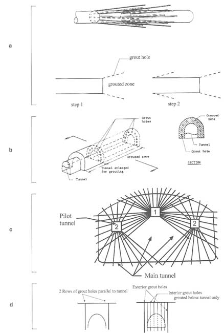
Tunnels are made impermeable through grouting by placing grout holes stepwise in a fanlike pattern from the tunnel (Figure 7.12a) or by placing them from enlarged sections parallel to the tunnel (Figure 7.12b). Radial arrangements (Figure 7.12c) are also possible, as are placements from the surface if the tunnels are shallow (Figure 7.12d). Arrangements as shown in Figure 7.12 can also be applied to waste storage isolation.
In all cases where zones of fractured rock are grouted to form a cutoff, grout holes are usually placed in single (parallel) rows, multiple rows, or radial patterns. The spacing of the grout holes depends on the flow and solidification characteristics of the grout such that continuously grouted zones are produced. Because it is very difficult to predict grout flow and hole spacing, an empirical procedure based on so-called split spacing is used. Grouting starts with a relatively large spacing of primary grout holes and continues by locating new holes midway between existing ones until the desired performance of the grouted zone is achieved. The split-spaced hole may be used to conduct a permeability test before deciding on further grouting. This procedure actually characterizes grouting in general; a grout is injected, and its behavior is observed during injection (flow/pressure behavior) and afterwards (reach, effect on rock mass properties). Based
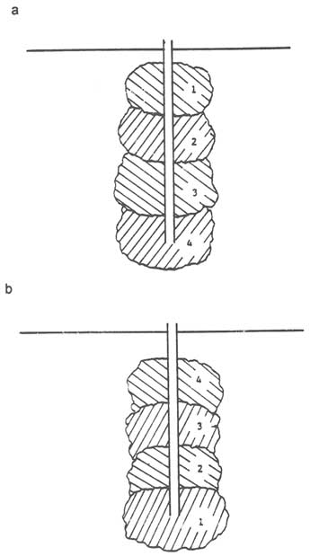
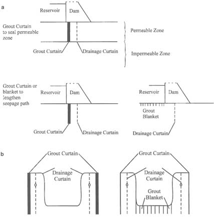
FIGURE 7.11 Grouting to reduce permeability in (a) dams and reservoirs using curtains and blankets and (b) foundation excavations.
on this information, more grout is injected through the same hole in one of the procedures mentioned earlier, or grout is injected in new holes, as discussed above. This is a classic application of the adaptable/observational methods (see also "Adaptable/Observational Methods," later in this chapter). Limited analytical prediction is possible (see below), but much of the grouting procedure is based on experience and on careful application of the adaptable/observational approach. The sequencing of grouting in single and multiple holes is not ad hoc but is a carefully planned engineering process.
From this description of impermeabilization grouting for dams, excavations, and tunnels, it should be evident that the same procedures can be used to strengthen and stiffen weak or deformable fractured rock masses. Most clay-based suspensions and "metathetical precipitation" solutions can only be used for impermeabili-
zation. Depending on temperature, some polymers do not have satisfactory resistances and stiffnesses. On the other hand, most other chemical grouts will actually increase the stiffness and strength of rock masses or any ground for that matter.
Grouting, whether for impermeabilization, strengthening, or stiffening, has a number of potentially negative effects. The first is the contaminating effect of grout components. If the grout components do not solidify or are eroded or leached after injection, they may contaminate groundwater. Second, through the creation of an impermeable zone, water pressures will increase upstream. Pressure buildups behind excavation walls (Figure 7.11b) or behind grouted zones under dams and in dam abutments (Figure 7.11a) may endanger their stability (see "Creation or Extension of Fractures Owing to Increases in Fluid Pressures," earlier in this chapter). It is advantageous to combine grouting with drainage, as indicated in Figure 7.11. (In some cases, similar considerations apply in tunneling.) Finally, grouts may not be permanently effective. Grout pressures may hydraulically fracture the rock mass and inadvertently worsen the condition they are intended to improve. Leaching and erosion, particularly if high water pressures exist, may reduce the intended effect of the grout. This is not a problem if grouting is used for construction purposes around foundation excavations or tunnels, but it is a problem in dams and in long-term waste isolation.
Models for Grouting
Analyzing flow through a rock mass containing zones of reduced permeability is usually based on the assumption of a heterogeneous medium, where the grouted rock is modeled by an impermeable/low-permeability layer in a higher-permeability rock mass. In quasi-continuum approaches, flow net distortions (e.g., Cedergren, 1977) can be used to represent different permeabilities, and numerical methods can be applied correspondingly. If discontinuum approaches are used, the permeable rock mass is modeled as a discontinuum; the cutoff is usually modeled as a continuum. This combination is somewhat problematic, but, in principle, is similar to flow through combinations of soil and fractured rock. The usual procedure is to separate the two zones and calculate flow through the fractured medium with the methods described in Chapter 6, under initially assumed boundary conditions at the continuum-discontinuum interface. The process is iterated until the results of the continuum and discontinuum analysis at the interface are within a specified tolerance.
Analyzing flow and solidification of grout is extremely difficult for the reasons explained earlier. Basically, fracture flow models, in which the flow characteristics of the grout change with time, could be used. An alternative is the one by Stille et al. (1992), which models the sequential blocking of fractures as grouting proceeds. Grout is assumed to flow in the channels in joint planes. When grout is injected into a single channel, injection proceeds until the grout
stops, because the shear forces along the wall of the channel balance the driving pressure. The model assumes that the grout behaves as a Bingham fluid (i.e., the model does not account for the particle size distribution in the grout), which means that the shear force per unit area of contact between the grout and the fracture channel wall is constant along the length of the fracture. Grout penetration can be calculated as a function of channel size distribution. This model provides a means of designing an appropriate grouting fluid as determined by the geometry of the fracture network. A drawback of this approach is the uncertainty in knowing the in situ boundary conditions. Consequently, usually only adaptable/observational approaches can be applied in which the grouting procedure is planned based on past experience or some initial laboratory or field tests, which are then adapted on the basis of field observations.
REDISTRIBUTION OF EXISTING SOLIDS BY CHEMICAL PROCESSES
This section addresses changes in the geometry of the void spaces (pores and fractures) resulting from chemical processes. Altering the solid framework can drastically increase or decrease the permeability and porosity of the system, which in turn will modify flow and transport phenomena, possibly leading to more changes in the solid framework.
Chemical Mobilization and Swelling of Clays
Many fractured rocks contain clay in the rock matrix or as fillers in fractures and pores. Clay particles can be mobilized by changes in fluid chemistry and transported in suspension, or the clay can swell. Clays can be mobilized by a change in the nature or concentration of the electrolytes in solution. Clay particles generally have a negative electrical charge, which is neutralized by exchange cations and water dipoles in the form of a so-called double layer. The properties of this double layer are strongly affected by the concentration of the electrolyte solution and the valence and size of its constituent ions.
Smectites and mixed-layer clays have, in addition to this double layer, layers of water molecules that contain exchange cations sandwiched between negatively charged sheets of aluminosilicates. This makes them particularly susceptible to changes in the valence and concentration of surrounding electrolyte solutions. Higher valences or ion concentrations decrease the number of water molecules layers and, consequently, the size of the hydrated clay particle, causing the clays to shrink. A particle stuck in a constriction may shrink enough to become mobile.
If fractures are filled with clay or if the fracture wall rock is argillaceous (i.e., clay rich), exposure of the rock to water may lead to swelling of the clay minerals. In this case there is a time-dependent decrease in the void volume of the fracture. A number of different swelling mechanisms exist in argillaceous
rock. Mechanical swelling is the inverse of consolidation in that a decrease in applied stresses will lead to a reduction in pore pressures. Consequently, pore water will flow into the destressed depressurized zone and cause swelling. Physicochemical swelling can be osmotic interparticle swelling—that is, water being attracted into the double-layer zone surrounding clay particles—or it can be swelling in which water is incorporated into the clay layers, such as occurs in smectite. Other rocks such as anhydrite also swell owing to exposure of fractures to water and stress relief, but the mechanism is different. Swelling of fracture fillings causes clogging, which leads to pore pressure increases that may be detrimental to stability.
Dissolution and Precipitation
Solids can be redistributed by being dissolved, transported in solution, and precipitated in a new location. In general, this process will increase permeability in regions from which material is being removed and decrease it in regions where material is being deposited. The redistribution of solids in fractures can occur with or without changes in the overall mineral assemblage making up the rock mass. A given mineral may be dissolved at one place and precipitated in another, or an existing mineral may be dissolved and a different one precipitated elsewhere (Phillips, 1991). Some geothermal systems are thought to be "self-sealing" through a mechanism involving the dissolution of minerals near the source of the heat and reprecipitation in fractures at some distance from the heat source. These processes are also the basis of "in situ mining," in which economic minerals are leached from the rock by solution mining (U.S. Bureau of Mines, 1989).
Even in mineralogically simple systems, the overall processes of flow, dissolution, transport, and precipitation are coupled in extremely complex ways. Solubility of a given mineral is a function of temperature, pressure, and the composition of the aqueous phase (i.e., the types and concentrations of ionic species in solution). Changes in any of these variables during engineering operations can produce significant large-scale alterations of the spatial permeability distribution. These alterations, in turn, affect flow velocity, which affects dissolution, transport, and precipitation.
Solubility is also a function of other solid minerals present in the system and the conditions of phase equilibrium among different solid phases. Metastable or unstable combinations of minerals are known to persist over geologically significant time periods, presumably because reaction rates are very slow. In such cases the state of the system is controlled by chemical kinetics, rather than thermodynamic equilibrium conditions.
Increased temperature can either increase the solubility of a mineral (e.g., halite) or decrease its solubility (e.g., gypsum, calcite), depending on the chemical species involved. Similar species-specific differences in solubility are observed for fluid pressure changes.
As in other processes involving phase equilibria, dissolution and precipitation reactions depend on chemical potential or partial molar Gibbs free energy. If the chemical potential of a given substance is not the same in all phases in which it is present, the system is not in equilibrium. Mass will be transferred spontaneously from the phase with the higher chemical potential to the phase with the lower chemical potential.
The direction of change induced by perturbations in stress, temperature, fluid pressure, or composition introduced by an engineering operation is easily determined by calculating the changes in chemical potentials. For example, in the case of "pressure solution" an increase in pressure will increase the chemical potential of a species in the solid phase more than in the solution phase. Therefore, there will be a spontaneous transfer of mass from solid to solution, and the void volume of the system will be increased. This volume increase in turn counteracts the increase in pressure. The reverse analysis works equally well for precipitation. If one phase is an aqueous solution and the other a porous or fractured solid, the partial molal quantities can be used to determine the direction of mass transfer, that is, which phase tends to gain mass and which tends to lose.
The example given above is an illustration of Le Chatelier's principle: if a system at equilibrium is disturbed, the resulting changes are always in such a direction as to offset the disturbance and restore equilibrium. Similar results for temperature changes are available in any standard chemical thermodynamics text, with the negative of the partial molal entropy playing the role of the partial molal volume.
The discussion above, has emphasized one of the more powerful principles for analyzing changes involving dissolution or precipitation caused by changes in the temperature or pressure of a system—namely, equilibrium thermodynamics. Similar analyses can be made to determine changes in concentration and the directions of chemical reactions. However, it should be noted that thermodynamics provides no information about the rates of any of the processes involved, whether physical or chemical. To consider these effects, additional theory and experimental measurements are necessary to provide parameters for the rate equations. The rates of chemical reactions may be kinetically controlled or they may be controlled by the flow system, depending on the fluid velocities and the particular reaction. In fact, some parts of the system, with slow fluid movement, may be controlled by equilibrium conditions, and other parts, with more rapid fluid movement, may be controlled by kinetics.
Models
The models used to study dissolution and precipitation are essentially the same as those used to study reactive transport as described in Chapter 6. An example of calculations for the redistribution of silica in a fracture flow system in geothermal applications is given by Lai (1986). In this case the thermodynamic 2
data base for silica is well understood, and the chemistry is relatively simple. Lai was able to neglect the effect of pressure and model dissolution and precipitation as a function of temperature. However, precipitation and dissolution of other very common fracture fillings, such as calcite, have not been modeled because of the complexity of the chemistry (e.g., buffering and pH dependence in the case of calcite) or the lack of thermodynamic data.
Alteration of Existing Solids
This section is concerned with changes in which a solid is altered by a solid-state phase change that changes the density (and hence the volume) of the solid grains, with accompanying changes in porosity and permeability. For example, the siliceous Monterey formation in California was deposited as an ooze of diatom skeletons composed of amorphous silica. As the depth of burial increased, the amorphous silica was converted to the crystalline-phase cristobalite, which in turn was converted to microcrystalline quartz. This sequence is a key factor in the development of fracture permeability in the Monterey formation and required millions of years because the rate of burial is low and the rates of solid-state reactions are very slow at low-to-moderate temperatures. Other examples of solid-state phase changes include the transformation of aragonite, the crystalline form of calcium carbonate generally produced by biological processes, to calcite, the form generally found in limestones.
At typical engineering time scales, solid-state phase transitions are not usually important because reaction rates are very slow. These effects may be important at the high temperatures generated by in situ combustion methods for enhanced oil recovery, because the rates of most reactions increase rapidly with increasing temperature. Solid-state phase transitions may also be important at the elevated rock temperatures expected around nuclear waste repositories. In this case the time of interest is many thousands of years rather than a few decades, so even a small increase in reaction rate could produce significant effects.
The quantification of the chemical phenomena described in this section can be extremely complex. There are a large number of important parameters. For many reactions the thermodynamic data base is not available. Even if it were, natural mineralogical heterogeneity is rarely if ever quantified. Finally, the flow system itself may not be well understood. There is significant need for research into effective methods of predicting reactive behavior. These should include laboratory and in situ experiments that are designed as analogs to the reactions of interest and that provide an opportunity for heuristic extrapolation.
Colloidal Suspensions
A special class of chemical reactions arises in certain waste disposal applications, including nuclear waste disposal. Under some conditions, chemical reac-
tions between the waste and water can produce colloidal suspensions that contain radionuclides. Colloidal suspensions may be capable of transporting much higher concentrations of radionuclides than true solutions. Colloids are generally repelled from the walls of fractures. Consequently, they travel near the centers of the fractures and may be transported more quickly than the average fluid flow velocity.
New information about colloidal behavior has come from recent work by Wan and Wilson (1994a,b) and Wan et al. (1994). Wan and co-workers have shown that colloids are essentially hydrophobic and consequently are attracted to the interfaces between water and air. This phenomenon could have a significant effect on the transport of contaminants under two-phase conditions. In particular, buoyant flow of gas bubbles with entrained colloids may be a possible mechanism for the transport of radionuclides in fractures.
ENGINEERING UNDER UNCERTAIN CONDITIONS
Problems involving changes to fracture systems in engineering and engineering geology involve uncertainty. The basic problem is a lack of data about the heterogeneous medium and an inadequate understanding of the coupled processes involved. The fracture geometry, mechanical properties, water pressure, flow, and chemical conditions in a rock mass are usually ill defined. Design and construction or, more generally, engineering decisions must consider this intrinsic uncertainty. This can be done in several ways, as explained in the following sections.
Reducing Uncertainty
One way to reduce uncertainty is through characterization efforts. A characterization resulting in the complete elimination of uncertainty is, however, not possible. Tradeoffs between the cost of further characterization and the benefits of reducing the uncertainty must be evaluated (Einstein et al., 1976).
Explicit Consideration of Uncertainty in Decision Making
The best-known approach is design with a safety factor or several safety factors. The design parameters are chosen such that design performance has a large margin of safety. Safety factor design does not guarantee safe performance because the distribution of possible performances is not determined. Partial safety factor design is somewhat more robust. In this case each of the major parameters is associated with a safety factor that reflects the uncertainties and importance of the parameter. Another approach is reliability and risk analysis (Ashley et al., 1979). In this approach, probabilities of malperformance are determined on the basis of uncertainties in the parameters. The risk involved in choosing a particular
design is explicitly determined and can be compared to the consequences of mitigation or the consequences (i.e., cost) of choosing a design with a reduced risk.
Adaptable/Observational Methods
As shown in Figure 7.13, a design is chosen on the basis of the most likely expected performance, which can be determined formally or intuitively. Simultaneously, contingency designs are developed to address conditions that deviate from the most likely case. Most importantly, performance criteria and monitoring approaches are included in all designs. The monitored performance is compared with the target performance, and, if deviations are observed, the appropriate contingency design is chosen. Minor adaptations can be made ad hoc. Peck (1969) and Einstein (1978) review many of the applicable methods.
Clearly, combinations of the three approaches discussed here are possible, such as determining the distribution of possible performances, and then using the performances to evaluate the benefits of further exploration before deciding on the most likely performance.
SUMMARY OF DEFICIENCIES AND RESEARCH NEEDS
The preceding discussion of rock-fracture-related problems in civil and mining engineering and engineering geology identified a number of problems:
-
It is not possible to completely characterize the geometric, mechanical, and chemical properties of rock masses. Exploration methods often have inadequate ranges of resolution and penetration and are too expensive.
-
Even with advances in exploration methods, there will always be uncertainties in rock mass characterization. Further formalization of adaptable analysis-design procedures is required, and, particularly, procedures are needed that allow quick adaptation as observations provide new information.
-
Clearly, any progress in knowledge about the geometry, mechanics, and mineralogy of individual fractures and fracture systems is desirable. Most important are relationships between geometry, mechanical behavior, and the creation of new fractures.
-
Knowledge of the long-term behavior of most rock mass changes is unreliable.
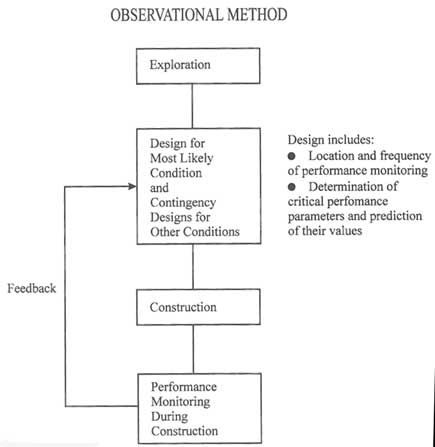
APPENDIX 7.A
NATURAL FRACTURING
The basic mechanics of the fracturing process provide insights into natural fracturing deep within the earth's crust. For this case it is appropriate to assume that the formations are massive with continuous field and property gradients. The vertical gradient of stress is proportional to rock density and is larger than the vertical fluid pressure gradients, which means that the effective stress is decreasing in the upward direction. This stress gradient promotes upward propagation of hydrofractures, as illustrated in Figure 7.A1, which shows results from
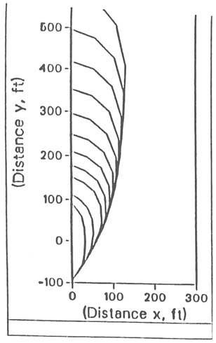
FIGURE 7.A1 Propagation of a vertical hydrofracture. After Clifton (1989).
a numerical simulation of a hydraulic fracture with a fluid source centered at the origin. The fracture front progresses, in time, from a near-radial shape to an elongated shape.
The rate of penetration and degree of vertical preference are governed by the viscous dissipation of the vertical pressure gradient. The preference for vertical growth from a fluid source of massive horizontal dimension will provide parallel sets of fractures.
The interaction of multiple fractures is influenced by the altered stress field around the fractures caused by their deformation. Furthermore, in massive formations the magnitude of the negative effective stress (i.e., pressure) required to propagate a fracture tends to decrease as the fracture dimension increases. The decreasing pressure requirement can be offset by increasing viscosity as the intruding fluid rises and is cooled as it moves away from a heat source.
Because they require less pressure in order to propagate, larger fractures will propagate preferentially when all the fractures are connected by a common pressure source. The existing fractures induce a compressive stress in the direction normal to the fracture plane on a scale proportional to the size of the fracture. The scale-dependent stress increase tends to close neighboring fractures, particularly smaller ones with smaller apertures. The coupling of the scale-dependent stress increase and the preference for growth of larger fractures will define the size distribution and spacing between fractures of various sizes. Additional features of natural hydraulic fracture networks can be illuminated by the comprehensive numerical models used in the petroleum industry (Gidley et al., 1989, Chapters 3, 4, and 5).
APPENDIX 7.B
DRAINAGE METHODS IN CONSTRUCTION
Water flow from excavation surfaces may impede construction (operation) or erode fracture fillings or fracture wall rocks. Water flow can be prevented or reduced by applying so-called drainage layers to the excavation walls. These external drainage layers consist of relatively permeable (low cement content) shotcrete or geotextiles (Figure 7.B1a), which are frequently applied in combination with an impermeable seal to form a geomembrane. If drainage occurs from only a few fractures, hoses can be inserted into the fractures to relieve the flow (Figure 7.B1b). Frequently, short holes are drilled into the rock mass to capture the flow before it reaches the surface of the excavation (Figure 7.B1c). This approach may be used in combination with hoses or drainage layers.
External drainage involves the capture of water or gas near an excavated or natural surface. When incorporated into permanent structures, this type of drainage must be a carefully designed system of seals and pipes for the removal of water (Figure 7.B1d). Water pressures should not exceed specified limits to prevent overloading of the seal or the permanent supports. However, a reduction in water pressure may result in the precipitation of calcite in fractures if the water is carrying calcite in solution.
The purpose of internal drainage is to capture water (gas) at a distance from the natural or excavated surface. This type of drainage can be used to induce favorable stress conditions in a zone near the surface and avoid some of the above-mentioned problems when water drains directly at the surface.
Many internal drainage methods make use of boreholes that intercept fractures in the rock mass. Boreholes can be arranged in several geometries as shown in Figure 7.B1e. Possible arrangements include single or multiple rows of vertical or inclined holes to form ''drainage curtains"; drainage curtains are also used in conjunction with dams (Figure 7.B1f).
Borehole drainage curtains can be replaced by so-called permeable cutoffs, which are excavated trenches or slots filled with permeable materials (Figure 7.B1 g). The objective of all these methods is to intercept fractures that are under high pore pressures or that are connected to fracture systems under high pore pressures. Depending on the fracture and fracture system geometry, this may require that boreholes be oriented other than in simple vertical or horizontal rows. Figure 7.B1h shows a drainage gallery (tunnel) that can be used alone or in conjunction with drain holes to improve drainage. Internal drainage can also be induced by increasing the permeability of fractured zones in the rock mass. Methods for accomplishing this involve the creation of new fractures by blasting or hydraulic fracturing and increasing fracture conductivity by propping. These methods are discussed earlier in this chapter, under "Creation or Extension of Fractures Owing to Increases in Fluid Pressures."
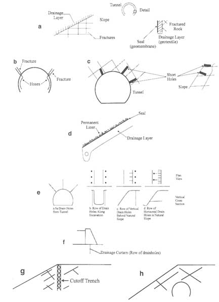
FIGURE 7.B1 Schematic illustration of drainage methods. (a) External drainage layers. (b) Drainage through hoses inserted into fractures. (c) Drainage through short holes drilled into the rock mass. (d) Drainage beneath a permanent liner. (e) Internal drainage through boreholes. (f) Drainage curtain in a dam foundation. (g) Drainage cutoff trench. (h) Drainage tunnel.
Fluids from internal drainage can be removed through gravity flow or pumping. Erosion of fracture fillers or fracture wall rock can be minimized by placing filters and suitably graded materials into the drainage facilities.
REFERENCES
Advani, S. H., T. S. Lee and J. K. Lee. 1990. Three-dimensional modeling of hydraulic fractures in layered media: Part I—finite element formulations. ASME Journal of Energy Research Technology, 112:1–9.
Asgian, M. 1989. A numerical model of fluid flow in deformable naturally fractured rock masses. International Journal of Rock Mechanics and Mining Science and Geomechanics Abstracts, 26:(3/4) 317–328.
Ashley, D. B., H. H. Einstein, and E. Tse. 1979. Advantages and limitations of adaptable tunnel design—construction methods. Pp. 989–1011 in Proceedings of the 4th Rapid Excavation and Tunneling Conference. Richardson, Tex.: American Institute of Mining, Metallurgical and Petroleum Engineers.
Biot, M. A. 1956. Thermoelasticity and irreversible thermodynamics. Journal of Applied Physics, 27:240–253.
Boley, B. A., and J. H. Weiner. 1960. Theory of Thermal Stresses. New York: John Wiley & Sons.
Cambefort, H. 1964. Injection des Sols. Paris: Editions Eyrolles.
Cedergren, H. R. 1977. Seepage, Drainage, and Flownets. New York: John Wiley & Sons.
Clifton, R. J. 1989. Three-dimensional fracture-propagation models. In Recent Advances in Hydraulic Fracturing, J. L. Gidley, S. A. Holditch, D. E. Nierode, and R. W. Veatch, eds. Monograph Series 12. Richardson, Tex.: Society of Petroleum Engineers.
Clifton, R. J., and J. J. Wang. 1988. Multiple fluids, proppant transport and thermal effects in 3-dimensional simulation of hydraulic fracturing. Paper presented at the 63rd Annual Technical Conference, Oct. 2-5, 1988, Houston, Tex. SPE 18198. Richardson, Tex.: Society of Petroleum Engineers.
DECOVALEX. 1991. Bench-mark test 2: multiple fracture model. DECOVALEX Doc 91/104. DECOVALEX Secretariat. Stockholm: Royal Institute of Technology.
De Marsily, G. 1987. An overview of coupled processes with emphasis on geohydrology. In Coupled Processes Associated with Nuclear Waste Repositories, C. F. Tsang, ed. New York: Academic Press.
Doughty, C., and K. Pruess. 1988. A semianalytical solution for heat-pipe effects near high-level nuclear waste packages buried in partially saturated geological media. International Journal of Heat Mass Transfer, 31:79-90.
Dvorkin, J., and A. Nur. 1992. Filtration fronts in pressure compliant reservoirs. Geophysics, 57:1089-1092.
Economides, M. J., and K. G. Nolte. 1989. Reservoir Stimulation, Second Edition. Englewood Cliffs, N.J.: Prentice-Hall.
Einstein, H. H. 1978. Observational Tunnel Design—Construction Methods in the U.S. Shotcrete for Underground Support III. New York: Engineering Foundations.
Einstein, H. H., D. A. Labreche, M. J. Markow, and G. B. Baecher. 1976. Decision analysis applied to rock tunnel exploration. Engineering Geology, 12(2):143–160.
Einstein, H. H., G. B. Baecher, and D. Veneziano. 1979. Risk analysis for rock slopes in open pit mines. MIT report 80–20 to U.S. Bureau of Mines, vol. III, Massachusetts Institute of Technology, Department of Civil Engineering, Cambridge, Mass.
Engelder, T. 1993. Stress Regimes in the Lithosphere. Princeton, N.J.: Princeton University Press, 457 pp.
Fredrick, J. T., and Wong. 1986. Micromechanics of thermally induced cracking in three crustal rocks. Journal of Geophysical Research, 91:12,743–12,764.
Geertsma, J., and F. de Klerk. 1969. A rapid method of predicting width and extent of hydraulic induced fractures. Journal of Petroleum Technology, Dec., pp. 1571–1581.
Gidley, J. L., S. A. Holditch, P. Nierode, and R. Veach, eds. 1989. Recent Advances in Hydraulic Fracturing, vol. 12. Richardson, Tex.: Society of Petroleum Engineers.
Goodman, R. E. 1976. Methods of Geological Engineering. St. Paul, Minn.: West Publishing.
Hendron, A. J., E. J. Cording, and A. K. Aiyer. 1971. Analytical and graphical methods for the analysis of slopes in rock masses. Technical Report No. 36, Nuclear Cratering Group.
Hoek, E., and J. W. Bray: 1981. Rock Slope Engineering, 3d ed. London: The Institute of Mining and Metallurgy.
Hunt, J. R., L. McDowell-Boyer, and N. Sitar. 1987. Colloid migration in porous media: an analysis of mechanisms. Pp. 453–472 in Coupled Processes Associated with Nuclear Waste Repositories, C. F. Tsang, ed. New York: Academic Press.
Kafritsas, J. 1987. Coupled flow/deformation analysis with the distinct element method. Ph.D. thesis, Massachusetts Institute of Technology, Cambridge.
Khristianovich, S. A., and Y. P. Zheltov. 1955. Formation of vertical fractures by means of highly viscous liquids. Pp. 579–586 in Proceedings of the Fourth World Petroleum Congress, section II/T.O.P., paper 3, Rome.
Kohl, T., K. I. Evans, R. J. Hopkirk, and L. Rybach. 1996. Modeling of coupled hydraulic thermal and mechanical processes in the simulation of hot dry rock reservoir behavior. In Fractured and Jointed Rock Masses. Rotterdam: A. A. Balkema.
Lai, C. H. 1986. Mathematical models of thermal and chemical transport in geologic media . Ph.D. thesis, University of California, Berkeley, p. 188.
Lake, L. W. 1989. Enhanced Oil Recovery. Englewood Cliffs, N.J.: Prentice-Hall.
Londe, P. 1987. The Malpasset Dam failure. Engineering Geology, 24(1–4): 295–330.
Long, J. C. S., O. Olsson, S. Martel, and J. Black. 1992. Effects of excavation on water inflow to a drift. In Fractured and Jointed Rock Masses. Rotterdam: A. A. Balkema.
Majer, E. L., L. R. Myer, J. E. Peterson, Jr., K. Karasaki, J. C. S. Long, S.J. Martel, P. Blumling, and S. Vomvoris. 1990. Join Seismic, Hydrogeological, and Geomechanical Investigations of a Fracture Zone in the Grimsel Rock Laboratory. LBL-27913, Lawrence Berkeley Laboratory, Berkeley, Calif., 173 pp.
Martin, C. D., C. C. Davison, and C. T. Kozak. 1990. Characterizing normal stiffness and hydraulic conductivity of a major shear zone in granite. Pp. 549–556 in Rock Joints, Proceedings of the International Symposium on Rock Joints, N. Barton and O. Stephansson, eds. Rotterdam: A. A. Balkema.
Meade, R. B. 1991. Reservoirs and earthquakes. Engineering Geology, 30(314):245–262.
Meyer, B. R. 1989. Three-dimensional hydraulic fracturing simulation of personal computers: theory and comparison studies. SPE 19329. Pp. 213–230 in Proceedings of the Eastern Regional Meeting of Society of Petroleum Engineers, Morgantown, W. Va. Richardson, Tex.: Society of Petroleum Engineers.
Nolte, K. G. 1982. Fracture design considerations based on pressure analysis. SPE 10911. Paper presented at Cotton Valley Symposium of the Society of Petroleum Engineers, Tyler, Tex., May 20. Richardson, Tex.: Society of Petroleum Engineers.
Noorishad, J., P. A. Witherspoon, T. L. Brekke, and T. Maini. 1971. Methods for coupled stress and flow analysis of fractured dam foundations and rock slopes. Geotechnical Engineering Publication 71-6, University of California, Berkeley.
Noorishad, J., M. S. Ayatollahi, and P. A. Witherspoon. 1982. Coupled stress and fluid flow analysis of fractured rocks. International Journal of Rock Mechanics and Mining Sciences and Geomechanics Abstracts, 19:185–193.
Noorishad, J., C. F. Tsang, and P. A. Witherspoon. 1984. A coupled thermal-hydraulic-mechanical finite element model for saturated fractured porous rocks. Journal of Geophysical Research, 89 (B12):10,365–10,373.
Noorishad, J., C. F. Tsang, and P. A. Witherspoon. 1992. Theoretical and field studies of coupled hydromechanical behavior of fractured rocks: I—Development and verification of a numerical simulator. International Journal of Rock Mechanics and Mining Sciences and Geomechanics Abstracts, 29(4):401–409.
Olson, J. 1990. Fracture mechanics of joints and veins. Ph.D. dissertation, Stanford University, Stanford, Calif., p. 174.
Peck, R. B. 1969. Advantages and limitations of the observational method in applied soil mechanics. Geotechnique, 19:171–187.
Perkins, T. K., and J. A. Gonzalez. 1984. Changes in earth stresses around a wellbore caused by radially symmetrical pressure and temperature gradients. Society of Petroleum Engineers Journal, Apr., pp. 129–140.
Perkins, T. K., and J. A. Gonzalez. 1985. The effect of thermoelastic stresses on injection well fracturing. Society of Petroleum Engineers Journal, Feb., pp. 78–88.
Perkins, T. K., and L. R. Kern. 1961. Widths of hydraulic fractures. Journal of Petroleum Technology, Sept., pp. 937–949.
Phillips, O. M. 1991. Flow and Reactions in Permeable Rocks. New York: Cambridge University Press, pp. 57–58.
Prats, M. 1961. Effect of vertical fractures on reservoir behavior incompressible case. Society of Petroleum Engineers Journal, June, pp. 105–118.
Raghavan, R., J. D. T. Scorer, and F. G. Miller. 1972. An investigation by numerical methods of the effect of pressure-dependent rock and fluid properties on well flow tests. Society of Petroleum Engineers Journal, 12:267–275.
Rutqvist, J., J. Noorishad, O. Stephansson, and C. F. Tsang. 1992. Theoretical and field studies of coupled hydromechanical behavior of fractured rocks: 2. Field experiment and numerical modeling. International Journal of Rock Mechanics and Mining Sciences and Geomechanics Abstracts, 29 (4):411–419.
Settari, A., and M. P. Cleary. 1984. Three-dimensional simulation of hydraulic fracturing. Journal of Petroleum Technology, July, pp. 1177–1190.
Stephens, G., and B. Voight. 1982. Hydraulic fracture theory for conditions of thermal stress. International Journal of Rock Mechanics and Mining Science and Geomechanical Abstracts, 19:279–284.
Stille, H. G. Gustafson, V. Hakansson, and P. Olsson. 1992. Passage of water bearing fracture zones—experiences from grouting of the section I-1400 m of the tunnel. SKBPR 25-92-19, Swedish Nuclear Fuel and Waste Management Company, Stockholm.
Teufel, L., D. W. Rhett, and H. E. Farrell. 1991. Effect of Reservoir Depletion and pore pressure drawdown on in-situ stress and deformation in the Ekofisk Field, North Sea. Proceedings of the 32d U.S. Rock Mechanics Symposium. Rotterdam: A. A. Balkema.
Teufel, L. W. 1979. An experimental study of hydraulic fracture propagation in layered rock. Ph.D. thesis, Texas A&M University, College Station.
U.S. Bureau of Mines. 1989. In-situ leach mining. P. 107 in Proceedings: Bureau of Mines Technology Transfer Seminars. IC 9216, Pittsburgh, Pa.
Wall, J., A. Nur, and J. Dvorkin. 1991. A slug test method in reservoirs with pressure sensitive permeability. Pp. 95–105 in Proceedings of the 1991 Coalbed Methane Symposium, May 13-16, University of Alabama, Tuscaloosa.
Walsh, J. B. 1981. Effect of pore pressure and confining stress on fracture permeability. International Journal of Rock Mechanics and Mining Science and Geomechanics Abstracts, 18:429–435.
Wan, J., and J. L. Wilson. 1994a. Visualization of the role of the gas-water interface on the fate and transport of colloids in porous media. Water Resources Research, 30:11–23.
Wan, J., and J. L. Wilson. 1994b. Colloid transport in unsaturated porous media. Water Resources Research, 30:857–864.
Wan, J., J. L. Wilson, and T. L. Kieft. 1994. The effects of the gas-water interface on the fate and transport of microorganisms in unsaturated porous media. Applied and Environmental Microbiology, 60:509–516.
Wang, J. S. Y., C. F. Tsang, N. G. W. Cook, and P. A. Witherspoon. 1981. A study of regional temperature and thermohydrologic effects of an underground repository for nuclear wastes in hard rock. Journal of Geophysical Research, 86:3759–3770.
Warpinski, N. R. 1985. Measurement of width and pressure in a propagating hydraulic fracture. Society of Petroleum Engineers Journal, Feb., pp. 46–54.
Warpinski, N. R. 1991. Hydraulic fracturing in tight, fissured media. Journal of Petroleum Technology, Feb., p. 146.
Warpinski, N. R., and L. W. Teufel. 1987. Influence of geological discontinuities on hydraulic fracture propagation. Journal of Petroleum Technology, Feb., pp. 209–220.
Warpinski, N. R., Z. A. Moschovidia, C. D. Parker, and I. S. Abou-Sayed. 1994. Comparison study of hydraulic fracturing models—test case: GRI staged field experiment no. 3. SPE Production and Facilities, Feb., pp. 7–160.
Williams, D. B., et al. 1989. Impact of inducing fractures at Prudhoe Bay. Journal of Petroleum Technology, Oct., pp. 1096–1101.
Wittke, W. 1965. Verfahren zur Standsicherheitsberechnung starrer, auf ebenen Flächen gelagerter Körper und die Anwendung der Ergebnisse auf die Standsicherheitsberechhung von Felsböschungen, Heft 20. Karlsruhe: Veröffentlichungen des Institutes für Bodenmechanik und Grundbauder Technischen Hochschule Fridericiana.


