
4
Failure Modes
As discussed in chapters 2 and 3, most hot structures are fabricated from superalloys that have been tailored to meet the demands of turbine engine operation. Specific solutions to problems encountered under one set of operational conditions are often in conflict with those encountered under another set (Wood and Goldman, 1986). Thus, materials specialists have developed alloys that possess a balance of properties geared toward withstanding the most worrisome degradation mechanisms. As a result, alloying and processing of superalloys for high-temperature structural applications has historically focused on improving their creep resistance, with secondary goals of improving resistance to fatigue, oxidation, and hot corrosion (Sims et al., 1986).
This chapter reviews the failure modes experienced at high temperatures by current structural materials (i.e., superalloys) and their coatings. A case study of the use of failure modes to improve coating design is presented, using thermal barrier coatings (TBCs) as an example. The chapter concludes with a series of recommendations on future directions in research on environmental degradation modes.
DEGRADATION MECHANISMS OF STRUCTURAL MATERIALS
Degradation mechanisms for structural materials are a function of the engine operating conditions, engine mechanical design, and the component base materials. As a zero-order approximation, engine operating conditions determine operating temperature and structural loads, while engine design determines the amount of air made available to cool the hot structure. Table 4-1 summarizes the environmentally induced failure modes of interest (i.e., creep, fatigue, oxidation, and hot corrosion).
The first nickel-base alloys contained 20 percent chromium and successfully resisted oxidation within the operating temperatures then used because they formed a protective layer of chromia, Cr203. It was soon discovered that these alloys could be substantially strengthened with a coherent precipitate Ni3(Al, Ti), known as gamma-prime. However, the chromium content had to be reduced to increase the volume fraction of gamma-prime. While other elements could be added to make up for the loss in chromium, the alloys became more difficult to fabricate using existing methods (Stringer and Viswanathan, 1993).
As engine operating temperatures increased, chromia became less attractive as a protective scale because it oxidized further to the volatile compound of CrO3. Alumina (A1203) remained attractive, however. Unlike chromia, alumina by itself does not protect against hot corrosion caused by molten alkali metal sulfates (Stringer and Viswanathan, 1993). Generally 4- to 5-weight-percent aluminum suffices for both gamma-prime and alumina formation.
Grain boundaries become a weak component of the microstructure at high temperatures. Creep deformation occurs in the grain boundaries, for example. To increase creep resistance, many of the critical hot-section airfoils are cast with the grains aligned parallel to the direction of the principal stress axis. These are called directionally solidified castings. Ideally, these components are selected as a single-crystal airfoil with the desired crystallographic orientation. Elements cannot segregate to the grain boundaries in single-crystal blades and cause brittleness. Thus, alloying flexibility exists to design a material with inherently high resistance to creep, oxidation, and hot corrosion. Single-crystal blades can be used uncoated in certain aeronautical turbine applications, but they do not yet possess sufficient inherent corrosion resistance for industrial turbine use, which is much more demanding on service life (Stringer and Viswanathan, 1993).
The degradation modes common to cooled hot-section superalloy components include low-cycle thermal fatigue, oxidation, and creep, with creep being the least important factor because it is designed out. Combustor and turbine blade components also degrade during high-cycle fatigue processes. On the other hand, noncoated components, such as low-pressure turbine blades, are often creep limited.
DEGRADATION MECHANISMS OF COATINGS
Once it became apparent that it would be extremely difficult to develop structural materials that possessed all the desired high-temperature mechanical properties as well as environmental resistance, the functions were uncoupled. Structural alloys were developed to optimize mechanical properties, and coatings were developed to serve as physical
TABLE 4-1 Environmentally Induced High-Temperature Structural Material Failure Modes
|
Failure Mode |
Definition |
|
Creep |
Time-dependent, thermally activated inelastic deformation of a material. The rate of creep increases as the temperature increases for constant stress. |
|
High-Cycle Fatigue |
Microstructural damage mechanism that results from small stress amplitude cyclic loading, such as vibrations; failure will occur after a relatively large number of cycles. |
|
Low-Cycle Fatigue |
Microstructural damage mechanism that results from large stress amplitude cyclic loading; failure will occur after a relatively small number of cycles. Very abrupt thermal changes, such as from engine start and stop cycles, are the driving force for this failure mode. |
|
High-Temperature Oxidation |
Solid-gas chemical reaction that produces the oxide(s) of constituents within the solid. The rate of oxidation increases exponentially with temperature, certain oxides (notably those of aluminum and chromium) are slow growing and protective of the underlying substrate. |
|
Hot Corrosion |
Electrochemical reaction between substrate and molten salts, typically sodium and potassium sulfates. Two forms of hot corrosion are generally recognized: Type I (high temperature), which typically occurs between the temperatures of 820°C and 920°C (1500°F and 1700°F), with a maximum at about 870°C (1600°F), characterized by the buildup of a nonprotective oxide layer as oxidation and sulfidation destroy the metal substrate; and Type II (low-temperature), which typically occurs between 590°C and 820°C (1100°F and 1500°F), with a maximum at about 700°C (1300°F), often exhibiting pitting. |
barriers between aggressive environments and the substrate (Stringer and Viswanathan, 1993).
The structural materials degradation modes that are moderated by the traditional metallic protective coatings include oxidation and hot corrosion. In addition, TBCs insulate the underlying structure against the full effect of gas-path heat. They thus retard creep degradation and reduce the severity of the thermal gradients and transients in the structure that drive low-cycle fatigue processes. By dampening the amplitude of vibrations, some coatings can reduce high-cycle fatigue. However, no such coating to date has been found that can survive the aggressive turbine environment.
Table 4-2 summarizes the various failure modes that pertain to the coatings themselves. Historically, metal coatings (i.e., alumide, chromide, and MCrAlY) have been designed to withstand three types of environmental attack: high-temperature oxidation, high-temperature (Type I) hot corrosion, and low-temperature (Type II) hot corrosion. Figure 4-1 shows the range of temperatures over which these attacks occur. However, it should be kept in mind that the oxidation of the aluminide and chromide coatings at the coating/gas-path interface results in the formation of a protective oxide scale. Therefore, within this context, high-temperature oxidation is not purely a degradation mechanism. In addition to these failure modes, thermomechanical fatigue of coatings (and substrates) can occur as a result of cyclic and thermal loading of the component. Thermomechanical fatigue cracking in coatings, particularly around film-cooling holes, has often been observed in advanced engines. A TBC can reduce the magnitude of the thermomechanical fatigue strain range and can minimize or eliminate thermomechanical fatigue cracking.
Several other damage modes cause coating loss and accelerate the overall failure mechanism:1
-
mechanical distress to the coating, such as nicks and gouges, which is caused by objects ingested into the engine airstream
-
solid-state diffusion of elements between coating and substrate, which can lead to the loss of critical elements from the coating and formation of undesirable phases in the substrate
-
spallation caused by differential thermal expansion between the coating and the substrate, which can lead to mechanical failure of the coating
-
rumpling of metallic coatings as a result of creep
The coating degrades at two fronts during service: the coating/gas-path interface and the coating/substrate interface. At temperatures well below the incipient melting point of conventional superalloys, deterioration of the coating surface at the coating/gas-path interface tends to be a consequence of oxidation or hot corrosion. As the temperature rises, diffusion across the coating/substrate interface plays a greater role in
|
1 |
These damage modes can be addressed by proper design of the coating system (as discussed in chapter 5) and operational procedures. |
TABLE 4-2 Environmentally Induced High-Temperature Coating Failure Modes
|
Failure Mode |
Definition |
|
High-Temperature Oxidation |
Solid-gas chemical reaction that produces the oxide(s) of constituents within the solid. The rate of oxidation increases exponentially with temperature; certain oxides (notably those of aluminum and chromium) are slow growing and protective of the underlying substrate. |
|
Hot Corrosion |
Electrochemical reaction between metal and molten salts, typically sodium and potassium sulfates. Two forms of hot corrosion are generally recognized: Type I (high-temperature), which typically occurs between the temperatures of 820 and 920°C (1500°F and 1700°F), with a maximum at about 870°C (1600°F); and Type II (low-temperature), which typically occurs between 590 and 820°C (1100 and 1500°F), with a maximum at about 700°C (1300°F). |
|
Mechanical Distress |
Erosion and impact damage caused by the ingestion of particles in the air stream. |
|
Solid-State Diffusion |
Reduction of the aluminum content of the coating because of interdiffusion with the base metal. |
|
Spallation |
Loss of protective oxide at the coating/oxide interface. |
|
Thermomechanical Fatigue Cracking |
Long-term (i.e., over many cycles) formation and propagation of cracks because of external mechanical stresses and to residual stresses from lack of thermal expansion compatibility between the substrate and the coating |
degradation; compositional changes at this interface can also compromise the structural properties of the substrate.
The remainder of this section reviews the key characteristics of coating degradation and suggests areas in which additional knowledge is needed. The discussion is limited to commercial coatings for which service-derived experience is available.
High-Temperature Oxidation
At high temperatures, coatings that protect against oxidation form a compact, adherent oxide scale (usually A1203) that provides a barrier between the high-temperature gases and the underlying metal. Chromia scales (Cr203) have been used but offer less protection than alumina above 840-870°C (15501600°F) because chromia scale tends to sublimate to CrO3 above these temperatures. Without the protective scale, the coating, and ultimately the substrate, come under rapid attack.
The general case is that the oxide spalls repeatedly until it can no longer form. Then internal oxidation, caused by diffusion of oxygen into the coating, degrades the protective oxide scale. Figure 4-2 shows the result of high-temperature oxidation of a coating and its penetration to the base metal. In this example, an adherent, relatively uniform external oxide scale remains, but internal oxidation of the coating and base metal has occurred. Recent work (Smialek, 1991; Smialek and Tubbs, 1995) has demonstrated the enhancements to oxide adherence that can be achieved as a result of very tight control of contaminant levels (e.g., maintaining sulfur levels in the < 1 ppm range). Segregation at the metal/scale interface causes disruption of the bond and spallation of the oxide. In addition, oxygen-active elements such as hafnium and yttria are often added to coatings to improve the
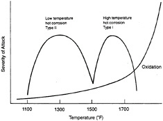
Figure 4-1 Types of high-temperature attack for metallic coatings (aluminide, chromide, MCrAlY, etc.) on nickel-base superalloys with approximate temperature regimes and severity of attack. Source: EPRI (1991). Copyright 1991. Electric Power Research Institute. EPRI GS-7334-L. Guidebook and Software for Specifying High-Temperature Coatings for Combustion Turbines. Reprinted with permission.
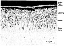
Figure 4-2 Micrograph of service-exposed CoCrAlY overlay coatings showing internal
oxidation of coating and base metal. Source EPRI (1991). Copyright 1991. Electric Power Research Institute. EPRI GS-7334-L. Guidebook and Software for Specifying High-Temperature Coatings for Combustion Turbines. Reprinted with permission.
adhesion of the oxide. The mechanisms proposed for the ''reactive element" effect on scale adhesion include (1) reducing the activity and mobility of sulfur, (2) mechanical pegging, (3) reducing void formation, (4) increasing scale plasticity, and (5) oxide doping.
The fundamental oxide-scale formation, growth, and breakdown have been studied for several years. Although some unresolved issues linger, high-temperature oxidation is relatively well understood. Less clear are the effects of oxidation from secondary species in the fuel and combustion air. The role of some of these contaminants have been studied; for instance, it is known that chlorine accelerates the rate of oxidation. However, a quantitative understanding of these effects is not well developed.
Hot Corrosion
Hot corrosion involves attack by molten salts, typically sodium and potassium sulfates, that enter the turbine hot section as contaminants from the air and fuel and can result in rapid loss of material (Stringer and Viswanathan, 1990). As indicated in table 4-2, there are two forms of hot corrosion: high-temperature (Type I) and low-temperature (Type II). The basic mechanisms of hot corrosion are relatively well understood, although there still remain areas of disagreement (Rapp and Zhang, 1994). The role of secondary elements (e.g., impurities such as chlorine, calcium, and iron from the local environment) is not as clear.
The key to continued protection against hot corrosion is maintaining the protective scale and keeping the hot-corrosion process in its initial, or incubation, period. Rapid loss of the coating and the underlying metal substrate will occur once the scale is lost or penetrated. The ideal protective scale would minimize solubility of the fused salt, a property determined by the combustion chemistry and operational environment. This criterion for petroleum-base fuels can generally be satisfied by either chromia or alumina, although alumina protects at higher operating temperatures than chromia.
A TBC degradation mechanism has been observed in service in which molten surface deposits can accelerate spalling of electron-beam physical vapor deposition (EB-PVD) and plasma-sprayed TBCs. Salt species in vapors from such sources as dirty fuel or marine environments can condense onto the coating surface. If the coating temperature is above the melting point of the salt, it can wick through the interconnected cracks and porosity of the coating (Miller, 1986). The wicked-in salt freezes on cooling, eliminating the strain tolerance mechanism of the coating and accelerating spallation (Palko et al., 1978; Miller, 1986; Strangman, 1990).
Mechanical Distress
Two related failure modes-mechanically induced erosion and impact damage-merit special consideration. Erosion results from particles in the air stream that abrade the coating and accelerate its loss. Impact damage occurs when a solid object in the air stream strikes the coating. These failure modes are sometimes overlooked because they can often be avoided by proper operating practice. However, these modes will become increasingly important as substrate materials are operated under conditions in which they offer little inherent protection against oxidation or other major failure modes. These failure modes are also a key concern in the retention of TBCs. These ceramic coatings are inherently more vulnerable to impact damage and erosion than metallic coatings.
Creep of stand-alone metallic coatings at higher temperatures can cause rumpling of the surface of coated components resulting in degradation of performance and durability. Application of a TBC may alleviate the problem by lowering the temperature of the metallic coating (Bose and DeMasi-Marcin, 1995). However, plastic instability of bondcoats for TBCs is still a potential problem at higher temperatures, and work on creep-resistant bondcoats is continuing (Brindley, 1995).
Solid-State Diffusion
The loss of aluminum in the coating, caused by diffusion of the coating with the base metal, ranks as another important degradation mode. Diffusion of aluminum into the base metal and base-metal elements into the coating reduce the concentration of aluminum in the coating that is available for forming alumina. A protective oxide can no longer re-form after
spallation once the aluminum concentrations fall below a certain level. The basic concepts of diffusion are well understood for simple systems, and the diffusion of complex, multielement systems containing multiple phases can be formally described (Nesbitt and Heckel, 1984). Obtaining actual interdiffusion coefficients and predicting the interdiffusion in these systems are formidable tasks, however. Consequently, reliance on empirical measurements of interdiffusion is necessary and usually sufficient for engineering purposes.
Spallation
Loss of oxide scale by spallation is the major concern for all coatings and poses a particular problem for coatings based on aluminum or chromium. Once again, a protective scale can no longer be maintained when the aluminum (or chromium) concentration falls below a critical level, usually cited as approximately 4- to 5-weight-percent aluminum.
Loss of the protective oxide at the coating/oxide interface is most damaging since an entirely new protective scale must be formed. Recent research indicates that spallation at this interface can be exacerbated by the presence of sulfur in the material. With the reduction of sulfur impurities, stepwise improvements have been observed in the adherence of protective oxides to superalloys (Smialek, 1991; Smialek and Tubbs, 1995), resulting in vastly improved oxidation resistance. Although studies have not completely elucidated the role of sulfur, lower levels of sulfur in both the superalloy base and its coating increase the coating's resistance to cyclic spallation.
TBC thickness is yet another concern. While it is obvious that a finite amount of TBC must be deposited in order to reap the benefit of a thermal barrier, increasing TBC thickness adds to component weight and accelerates spallation (Bose and DeMasi-Marcin, 1995).
Spallation of TBCs is an important failure mode. These ceramic coatings are not self-replenishing. Hence, spallation rapidly degrades the insulating properties of the coating and can accelerate attack of the underlying metallic bondcoat or substrate. This weakness of TBCs is discussed in greater detail in the next section.
A CASE STUDY: DEGRADATION OF THERMAL BARRIER COATINGS
Experimental and theoretical thermal characterization of TBCs has shown that they can provide significant thermal benefits to components in operation, but only if coating integrity is maintained. TBCs are applied on top of a MCrAlY coating; the TBC provides thermal insulation, and the MCrAlY protects the substrate against oxidation and hot corrosion. Zirconia is extensively used as a TBC since it has low thermal conductivity and a relatively high coefficient of thermal expansion. The zirconia used is partially stabilized in the metastable tetragonal phase with 6- to 8-weight-percent yttria. TBC coatings are applied using one of two processes: plasma spray and EB-PVD, as discussed in chapter 3.
Maintaining coating integrity for a TBC is more difficult than for metallic coatings because of the relatively large change in properties from the metallic substrate to the ceramic coating. The problem is exacerbated by the fact that TBCs provide the greatest efficiency benefit at the highest operating temperatures, where TBC failure is most likely to cause unacceptable component damage. Thus, while coatings with even lower conductivity may be possible (see chapter 8), the high variability of TBC thermal cycle life suggests that the use of these coatings to their full potential will depend on their susceptibility to failure.
The microstructure of the coating resulting from plasma spray differs significantly from that created by the EB-PVD processes (see figure 4-3). Hence the coating failure modes are not the same. Unlike the other coating types that may become ineffective through chemical degradation while the coating is still intact, the loss of the effective life of a TBC is
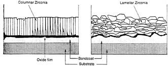
Figure 4-3 Comparison of the microstructure of EB-PVD and plasma-sprayed TBCs.
usually marked by the physical loss of the ceramic insulating layer. This loss occurs by one of two means: ceramic layer spallation or erosion of the ceramic layer.
Spallation
TBC spallation is a mechanical event that results in the removal of the ceramic layer by delamination from the bondcoat. Numerous processes may trigger this mechanical event, but the two main culprits are bondcoat oxidation and the strain generated by a thermal expansion mismatch between the ceramic top coat and the metallic components of the system (Miller and Lowell, 1982; Strangman, 1985; Hillery et al., 1988; Demasi-Marcin et al., 1989).
Data indicate that oxidation of the bondcoat and thermal expansion mismatch strains between the ceramic top coat and the metallic bondcoat have a synergistic effect on TBC failure. Under realistic conditions, the action of either alone cannot cause failure of plasma-sprayed (Miller and Lowell, 1982) or EB-PVD TBCs (Manning-Meier et al., 1991). This generality may not hold for conditions of extreme thermal transients, however, such as for rocket engine applications (Brindley and Nesbitt, 1988). Since oxidation and thermal-cycle strains must both be present to cause TBC failure, reducing either could dramatically improve TBC life. However, the details of degradation differ for EB-PVD and plasma-sprayed TBCs because of their substantially different ceramic layer and interface structures.
Plasma-Sprayed TBCs
Figure 4-4 shows the microstructure of a typical plasma-sprayed TBC. Failure of a plasma-sprayed TBC generally consists of cracking and spallation. Delamination cracking generally results from high in-plane compressive stresses that cause significant out-of-plane tensile stresses and produce delamination cracks parallel to the interface and near the peaks of the rough bondcoat. Finite-element analysis of a realistic rough interface of a plasma-sprayed TBC has shown that the thermal-cycle stresses in the ceramic layer at the bondcoat peaks are roughly two orders of magnitude higher than expected at a smooth interface (Ferguson et al., 1994). Thus the rough interface of a plasma-sprayed coating not only increases initial adherence with the ceramic layer through mechanical interlocking but also drives its delamination and reduction in life. Studies in which surface roughness was varied using an analytical (Evans et al., 1983) or numerical model (Ferguson et al., 1994) have identified the radius of curvature of the bondcoat peaks as the single most important feature in generating stress. Spacing and amplitude may also contribute.
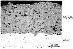
Figure 4-4 Photomicrograph of a plasma-sprayed TBC.
Out-of-plane cracks are also present in plasma-sprayed TBCs, but these result from processing and in-plane tensions applied to the ceramic layer during heating of the component. The out-of-plane cracks are not generally believed to be a problem for coating durability and could even enhance the strain tolerance of the coating. The out-of-plane cracks could play a role in spallation if they were to link major horizontal delamination cracks, and, in fact, out-of-plane cracks have been shown to accelerate spallation in thicker coatings (Bose and DeMasi-Marcin, 1995). These cracks could also reduce coating life by adding to the in-plane compressive stresses of the ceramic layer after cooling from high temperature. This could occur if the cracks were to open during heating but not close on cooling because of crack-face interference or cracking debris lodged in the crack.
Delamination in a plasma-sprayed TBC does not occur with a single cracking event but by progressive crack growth (demise et al., 1989; Cruse et al., 1992). Since cracks, flat pores, and abundant potential crack growth paths along splat boundaries are present in the as-processed structure, delamination cracking requires only crack growth and linkup through thermal fatigue. No crack initiation step is required. Thus, long service lives are possible if the strain imposed on the ceramic layer during thermal cycling is low enough. This requires a reduction in the strain imposed on the ceramic layer by thermal expansion mismatch, oxidation, or both.
EB-PVD TBCs
EB-PVD coatings tend to fail at the alumina-scale/bondcoat interface. Finite-element analysis modeling of the thermal cycle behavior of PVD coatings indicates that out-of-plane tensile stresses are well below the initially high adhesion strength of the alumina and even below the adhesion strength of coatings that have been thermally cycled (Manning-Meier et al., 1991). These low stresses primarily result
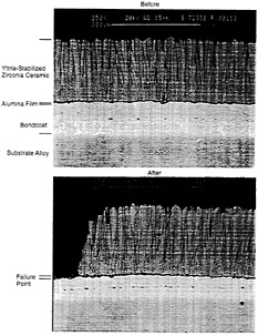
Figure 4-5 Photomicrographs of EB-PVD TBCs before and after failure.
from the smoothness of the interface between the bondcoat and the alumina layer. Figure 4-5 shows an EB-PVD coating before and after failure.
Although the calculated out-of-plane tensile stresses are lower than the adhesion strength of the coating, Manning-Meier et al. (1991) proposed that alumina delamination proceeds by progressive interfacial cracking from in-plane strains. Since the failure occurs at the alumina/bondcoat interface, progressive reduction of the adhesion of the alumina layer may also be involved in spallation of the TBC.
Oxidation is a larger fraction of the failure driver for PVD coatings than for plasma-spray coatings. The difference apparently arises because PVD coatings are less susceptible to thermal cycling damage (Manning-Meier et al., 1991). Continued growth of the oxide scale is believed to increase the compressive stresses applied to the ceramic layer during thermal cycling (Rigney et al., 1995). Several other mechanisms may increase the mechanical strain on the ceramic layer: sintering (Eaton and Novak, 1987; Manning-Meier et al., 1991), formation of high-volume or low-strength oxides at the bondcoat/ceramic interface (Lee and Sisson, 1994), and creep of the bondcoat (Hillery et al., 1988; Brindley and Whittenberger, 1993).
Erosion
TBCs are more susceptible to erosion than fully dense ceramic coatings because the strain-tolerant structure of TBCs includes crack like features. Furthermore, the relatively fine microstructure of the TBC coating means that the distance from one crack like feature to another is small and the crack length required to remove small portions of the coating is also quite small. Thus, the erosion rate, even compared with other porous ceramics, is expected to be high.
The degree of erosion depends on the density of particulates in the working gases and the angle of impingement. Particulate loading is expected to be higher for engines operating in dusty environments (e.g., aircraft engines ingesting debris during takeoff and landing and land-based or aircraft turbines in dusty sites or geographic regions such as the Middle East). Erosion can also stem from the particulates generated inside the engine (e.g., coking or salt shedding from parts that have deposited condensates). In all cases, erosion is more significant on the leading and trailing edges of rotating components than on static components or elsewhere on turbine blades.
Erosion removes the ceramic layer of the TBC and thereby removes the insulation it provides. Current practice is to design the leading edges of turbine blades as if no TBC were to be applied. Thus the heat load on the component will not exceed the design temperature for the leading edge if the TBC were eroded. As operating temperatures increase and the drive for higher efficiency continues, a solution to the leading-edge erosion problem will become increasingly important. Fabricating thicker TBCs at high-erosion areas is not an attractive solution because of the added weight of the coating and the increased likelihood of cooling hole blockage. A more satisfactory solution would be the development of an erosion-resistant coating or surface layer for current TBC materials.
RESEARCH OPPORTUNITIES
Engineers have a good understanding of how high-temperature oxides form. The role of minor elements (e.g., sulfur) in high-temperature oxidation and composition needs additional study, as do spallation of the oxide during both steady-state operation and thermal cycling.
The mechanisms of both low-and high-temperature hot corrosion are also relatively well understood. The role of secondary elements in hot corrosion needs additional study, as does the effect of mechanical integrity of the oxide scale during hot corrosion. In order to develop realistic fuel specifications, the resistance of coatings to hot corrosion in biomass and gasification environments (i.e., low sulfur but high alkali) needs clarification.
Accurately modeling the service life of coatings is also becoming increasingly important to designers who must rely on coatings to protect engine components (see appendix D).
Research is required to improve and apply models that can help optimize coating development and to provide more accurate estimates of the remaining coating life for in-service engines. More specifically, advances are required in (1) the understanding of the failure mechanisms and factors involved as a function of use conditions; and (2) the development of qualitative and quantitative life-prediction models based on all active failure mechanisms.


