
2
Undersea Vehicle Capabilities and Technologies
This chapter describes the types and capabilities of undersea vehicles that will provide the functions necessary to serve as undersea tools for science and industry and respond to vital national needs in the oceans. When describing its capability, it is essential to conceive of an undersea vehicle as a system that encompasses: (1) a vehicle platform plus vessel and shore-based support; (2) a payload of task-performing devices and sensors; (3) a human in control, located either remotely or on site; and (4) the technology and hardware necessary to support, launch, and retrieve the vehicle. This system level vehicle concept must take explicit account of potential missions and objectives.
This chapter points out the importance of system integration—the "glue" binding the human-vehicle system into a single operational unit. The contribution of each subsystem to the overall technical performance capability of the vehicle assembly is assessed in the system context. Advances in the technology and capabilities of some subsystems may provide more overall system performance benefits than would improvements in other subsystems. Finally, and very importantly, each key vehicle subsystem is assessed in regard to the current state of practice and where significant improvements can be made.
In this systems context, an assessment of the state of practice is the starting point for assessing vehicle technology and capability for responding to the nation's needs. An understanding of development trends and influences within, and external to, the undersea vehicle industry is the next important step in determining research and development strategies and priorities. Indeed, some of the valuable aspects of vehicle development are driven largely by advances in other industries, both domestic and foreign. This relationship is a natural process induced by the intense competition among a few small vehicle engineering and manufacturing organizations that must focus their limited development capital on adapting technologies to the special requirements of the undersea environment and missions. The committee identified those technologies that are vital to advances in undersea vehicle capability and are not already being pursued in other arenas.
VEHICLE SYSTEMS
Vehicle systems designs are driven by mission requirements, available technology, and cost. A system must be an effective combination of human operators and vehicle subsystems and components that are integrated to achieve optimal performance (see system elements schematic shown in Figure 2-1). Consequently, the task for builders and designers of a vehicle system is to integrate this multiplicity of subsystems into a working whole. The attributes of each subsystem will be assessed and established by the committee based on the state of technology, relative cost, and mission requirements.
For a given mission or task, designers and engineers begin by considering its particular requirements. These vary according to mission requirements for maximum depth, endurance in range and in time, and sensors; the optimal human role in command and control; power available; cost; and a host of other factors. Depending on these criteria, a particular type of vehicle (DSV, ROV, or AUV) is selected and its subsystems chosen to best fulfill mission requirements. Subsystem capabilities improve with time as technology develops, so the optimum solution in the near future may be significantly better than what is optimal using today's technology.
Table 2-1 summarizes typical capabilities and examples of DSVs, ROVs, and AUVs. The characteristics listed are generic, and there are exceptions; but the table outlines the characteristics and relative strengths and limitations inherent to each type of system.
DSVs place the human in the environment and benefit from the human's high-resolution, three-dimensional observation capability and full visual depth of field that is still superior to the observational capabilities provided by remote sensors. This capability enhances the performance of inspection and imaging tasks as well as manipulation. In general, today's DSVs have relatively large payload capacities and good manipulation capabilities but do not provide real-time feedback to the surface. Moreover, they require costly
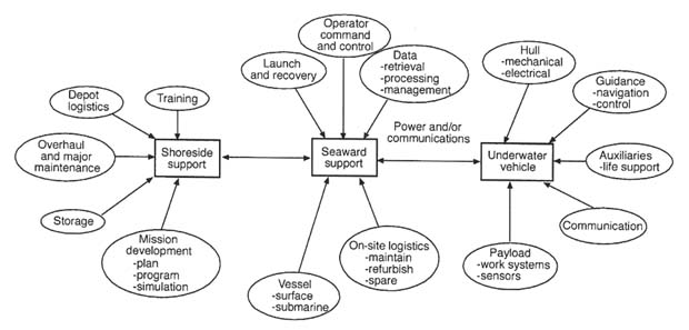
FIGURE 2-1 Schematic diagram of vehicle systems.
pressure housings and life support and safety systems for the human operators. DSV endurance at the work site is limited by prolonged surface periods for crew change and vehicle replenishment. The cost per operating hour is usually much greater than for other vehicle types because of the extra cost attributable to crew accommodation and life support, the larger surface support ship needed to handle the heavier human-occupied vehicle in launch and retrieval, and the more limited availability—therefore, the normally higher day rate—of support ships. In addition, the capital cost component of the day rate for DSVs is potentially higher than for unoccupied vehicles because they can be operated fewer hours due to human limitations.
In comparison to DSVs, ROVs provide greater endurance and greater range, including maneuverability of surface support vessels, at lower cost. Because life-safety support is not required, ROVs can operate in hazardous environments and provide simultaneous real-time observation and control to multiple remotely situated observers (Robison et al., 1992; Bowen and Walden, 1993).
AUVs are free from the tether restraint common to ROVs and can perform tasks with little or no operator input. However, AUVs must operate on a limited energy budget and can provide little real-time feedback to the operator, who is limited by the bandwidth available when using acoustic communication. However, new advances in task-level control architecture will enable the human to command tasks at high-level in real-time, and acoustical advances are continually expanding the available acoustic communication bandwidth.
DEEP SUBMERSIBLE VEHICLES
In the 1960s and 1970s many DSVs (with a human in situ) were in operation in a variety of different applications worldwide. Estimates indicate that more than 100 DSVs of all types were built during this time. DSVs have dominated ocean exploration, and some systems, such as Alvin, have been operational for the last three decades. DSVs continue to be used in support of certain military tasks and marine scientific research. However, few have been built recently (only four since 1990), and the number operating today is significantly less than it was 20 years ago. Since the 1970s, ROVs have replaced DSVs for most commercial work tasks, and the committee anticipates that ROVs will provide increasing support for marine science projects. However, there will continue to be certain vital exploration tasks that can be performed only by humans in situ.
Most contemporary DSVs require the on-site presence of a mother ship to provide logistical support for the vehicle and its personnel. The submersible's crew usually consists of a pilot and one or more observers. The observers are usually scientists, researchers, or technologists with an active part to play in conducting the mission. Due to limitations on human endurance and on-board power, mission times rarely exceed 8 hours, although some have extended to 16 hours or more. Emergency life support systems must be capable of operating for 72 hours beyond the maximum mission time.
The DSV places the crew directly at the site of interest. Visual observations are augmented for close-up inspections (less than 0.5-meter range) by video cameras, an important tool for direct observation (Robinson et al., 1992). Most DSVs are significantly larger than ROVs used in comparable missions. Its size makes the DSV a stable platform to support viewing and manipulative tasks, including biological and geological sampling. However, because it is essential for the DSV to be large enough to accommodate several persons, it is more difficult to handle at sea and more difficult to position when performing tasks in restricted work areas. Essentially, DSVs are vertical probes with limited horizontal range; therefore, they are less suitable for large-scale
TABLE 2-1 Comparative Undersea Vehicle Capabilities
|
|
DSVs |
ROVs |
AUVs |
|
DEFINITION |
Untethered, human-occupied, free-swimming, undersea vehicle |
Tethered, self-propelled vehicle with direct real-time control |
Untethered undersea vehicle, may be totally preprogrammed and equipped with decision aids to operate autonomously; or operation may be monitored and revised by control instructions transmitted by a data link. |
|
DEPTH |
Many to 1,000 m |
Very many to 500 m |
Several to 1,000 m |
|
|
Few to 3,000 m |
Many to 2,000 m |
Few to 3,000 m |
|
|
Very few to 6,000 m |
Few to 3,000 m |
Very few to 6,000 m |
|
|
One to 6,500 m |
Few to 6,000 m |
|
|
|
|
One to 11,000 m |
|
|
ENDURANCE |
|
|
|
|
Time |
Normally 8 hours, 24 to 72 hours max |
Indefinite, depending on reliability and operator endurance |
6 to 48 hours of propulsion May sit on bottom for extended periods |
|
Range |
< 50 km |
Limited in distance from host ship by tether |
350 km demonstrated; near-term potential 1,500 km, depending on energy source |
|
PAYLOAD |
1 to 3 people, 45 to 450 kg (100 to 1,000 lb); adaptable to tools and sensors |
45 to 1,590 kg (100 to 2,000 lb); adaptable to tools and sensors |
11 to 45 kg (25 to 100 lb); adaptable to measuring equipment, tools, and sensors |
|
SUPPORT |
|
|
|
|
Ship |
Most DSVs require large ship support; ship size varies with DSV size |
Depends on ROV size and mission requirements |
Medium—depends on AUV size and mission requirements |
|
Handling Systems |
Depend on DSV size |
Depends on ROV size |
Similar to ROVs, depending on AUV size |
|
Navigation Systems |
Relative to seafloor or surface vessel |
Relative to surface/seafloor |
Seafloor and inertial navigation |
|
STRENGTHS |
Direct human observation and manipulation |
Real-time feedback to operator, long endurance capability, low- cost per operating hour |
Potential for automated operations, ability to operate with or without human command and without tether; minimum surface support |
|
|
Real-time feedback to controller |
|
|
|
LIMITATIONS |
Large size, weight, and cost due to manned requirements |
Tether cable potentially limits maneuverability and range |
Energy supply |
|
|
|
|
Bandwidth of data link |
|
|
Limited mission time |
|
Capacity of internal recorders |
|
|
Potential personal hazards |
|
Limited work function complexity |
mapping and surveying operations. As with other systems, advances in propulsion, energy storage, and manipulators will contribute to DSV utility and may even reduce their cost. Developments incorporating innovative uses of materials have already reduced the size and weight of the next generation of DSVs, and a system designed to bring a single pilot to the deepest part of the ocean is in progress (Hawkes and Ballou, 1990; Broad, 1993).
REMOTELY OPERATED VEHICLES
ROVs are by far the most common type of undersea vehicle; more than 1,000 ROVs have been built since their introduction in the 1960s. ROVs connect to a surface vessel or platform by a tether that carries power and control signals and feedback data from the vehicle. Originally developed for the military, ROV technology was further developed by the civil sector in the early 1970s, when private firms developed ROVs in response to the needs of the offshore oil industry. ROVs were one factor that enabled the offshore industry to move beyond diver depth range. The results were reliable platforms serving a broad commercial market, with some technology transfer back to the military (McFarlane, 1987). ROVs continue to be used reliably in the offshore industry, and innovations in operational techniques and tool packages are expanding the scope of tasks these vehicles can perform (Langrock et al., 1992; Sucato, 1993). Nevertheless, ROVs are vertically operating systems that require significant surface support with attendant costs.
ROV manufacturing has been a highly competitive business. After attempts by several companies to compete in the rapidly growing offshore market of the 1970s, only one company, Perry Tritech, Inc., remains in the United States that builds full-size work platforms for the offshore industry. Worldwide, there probably are no more than five companies that have built more than one large ROV system. In the area of the smaller, low-cost ROV systems, a U.S. company, Deep Ocean Engineering, is the largest supplier among eight companies in the world that are in serial production of these vehicles.
Much of the commercial success gained by ROVs is due to the activities of service companies that operate vehicles under contract. Many of these companies began as commercial diving services, then gradually introduced ROVs as a lower cost alternative to many underwater tasks previously performed by divers. Other companies began as ROV service organizations only, following the pattern set by former successful commercial diving contractors. In the past two decades, the primary driver for ROV technology advancement has been commercial sector demand.
Light and medium-weight ROVs tend to have electrically powered thrusters. Heavy work-class ROV systems carry much larger payloads and tools, weigh up to 3,000 kilograms, and are fitted with hydraulic thrusters. These large ROVs found a niche in the offshore oil and gas industries and in the communication industry for underwater manipulation, cable burial, and inspection tasks. Large work-class ROVs are usually fitted with hydraulically powered manipulators, and some have protective cages that are used for launch and recovery. Nonmarine applications of ROVs, principally in nuclear and hydroelectric power plants and municipal water works, have evolved over the last two decades to provide small platforms for inspection of the radioactive, or potentially radioactive, components of nuclear power plants. The technical development and operational experience derived from the nuclear application has benefited the evolution and application of small vehicle designs for undersea application.
The mobility of ROVs is often restricted by tether drag, and their stability can be affected by wave action on the surface vessel, which is transferred down the tether. Despite the constraints to horizontal operations within the sea imposed by the tether, ROVs have provided a platform for conducting in situ observations within the water column with little disturbance of surrounding sea life. ROVs have also extended the horizontal search range for larger, more limited survey vehicles such as the DSV Alvin.
AUTONOMOUS UNDERWATER VEHICLES
Although AUV research has been under way for several decades, the technological challenges and applications are such that these vehicles have developed more slowly than ROVs. A few systems were in operation as testbeds in the 1970s, but it was not until the 1980s, with the advent of microprocessors and associated software architectures, that these systems began to approach truly autonomous operations (Walsh, 1994; Michel and Le Roux, 1981). AUVs have potential advantages over other vehicles types. Because they lack tethers and carry no human occupants, AUVs permit sensing in areas where humans cannot go, such as under ice, in militarily denied areas, or in missions to retrieve hazardous objects.
For the past two decades, more than 75 percent of AUV development has been funded by the military, so continued development of this technology may be vulnerable to reductions in defense research budgets (Walsh, 1994). Further, because most of this work has been experimental or directed at military objectives, experience with AUVs in support of scientific missions has been limited, and there has been virtually no experience in the commercial sector.1
Several different types of AUVs have already been developed, each designed to respond to one of a variety of missions. The AUSS, shown in Box 2-1, addresses large area search and detailed inspection requirements. The lightweight AUV sensor platform (e.g., Odyssey; see Box 2-2) aims at fulfilling needs for medium-area surveys under ice and in deep water. The long-duration, deep sea survey vehicles, for example, ABE (see Box 2-3), perform detailed inspections in deep water over long time periods (Michel et al., 1987; Walton, 1991; Walton et al., 1993; Bellingham et al., 1992; Bradley and Yoerger, 1993).
A recent emphasis in AUV development is on very small vehicles that can be deployed in large numbers to perform localized, relatively simple tasks such as shallow water mine clearance. These vehicles could be very simple and inexpensive, using basic sensor suites and commercial off-the-shelf electronics. Working together, a constellation of such devices could accomplish the same work as a single, larger AUV. Because multiple units could be programmed to carry out the same task, redundancy would provide reliability. Although this concept is quite new and unproven, it has shown sufficient progress and promise to warrant continuing development.
As AUVs enter nonmilitary applications, it is likely that marine science will become a primary early mission and technology driver. As the technology matures, a number of applications in the offshore oil and gas industry, such as cable laying and inspection, and in a variety of other fields can also be envisioned (Fricke, 1992; Collins, 1993; Asakawa et al., 1993; Walsh, 1994). At present, virtually all AUVs are experimental prototypes or proof-of-concept vehicles. None is in routine operational service.
AUVs in existence today are vehicles with limited decision making capabilities and endurance. The missions for AUVs call for simple data-gathering, conducting searches, performing surveys, and laying fiber-optic cable. However, until more advanced capabilities evolve, missions requiring probabilistic decision making and true autonomy will be developed only for high-value objectives. AUVs are still in their infancy, and the lack of operational experience with these vehicles in the open ocean marks them as an immature technology with very important future potential. Even now,
|
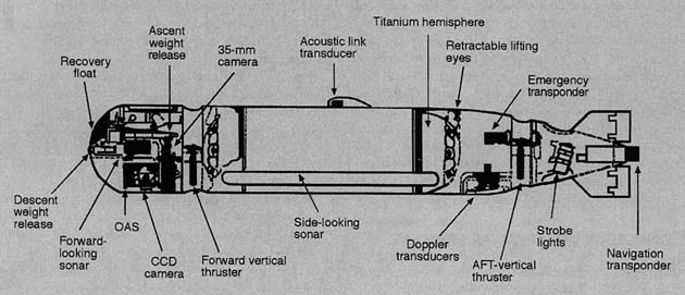
BOX 2-1 AUV Example: AUSS AUSS, the Advanced Unmanned Search System locates and inspects objects on the ocean bottom over wide areas. Mission logic allows the vehicle to perform a side-scan sonar search, break off the search when it identifies a target for close-in optical inspection, and then resume the search where it left off after imaging the target. AUSS acoustically transmits its imagery and data to a vehicle supervisor on a surface ship. The vehicle uses Doppler sonar and a gyrocompass to navigate. It employs a cylindrical graphite epoxy pressure hull with titanium ends. It has demonstrated sustained searches at a rate of 1 sq-nm/hr, including evaluating individual targets discovered along the search path.
 |
AUVs are capable of performing a number of clearly defined missions, but they have not been used because of their high initial development cost, lack of awareness of present vehicle capabilities, or lack of confidence by the potential user community.
Vehicle success in missions attainable with present system technical capability should provide both the experience and the support required for critical technology advancements to enable undertaking more complex missions. There is already evidence of this progress, as demonstrated by the AUV under ice operations in the arctic (Bellingham et al., 1993) and in recent Odyssey II surveys over the Juan de Fuca Ridge (see Chapter 3). For example, high-level (low-bandwidth) human control of tasks requiring use of manipulators in real-time is one important area under development. The human operator can command directly what is to be done with the object of interest within the water column or on the sea bed, and the vehicle manipulator system will plan and carry out that command in near real-time (Wang et al., 1992; 1993). This technology is similar to the approach being developed to deal with the time delays associated with robotic manipulation in space, and there has been some crossover of
|
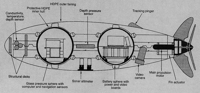
Box 2-2 AUV Example: ODYSSEY The Massachusetts Institute of Technology Sea Grant AUV Laboratory has built six Odyssey class vehicles, of which five are presently operational. The five operational vehicles, designated type Odyssey II, are being used for Autonomous Ocean Sampling Network (AOSN) research and for development of a rapid event-response capability. A variety of field operations have employed the vehicles, including operations of the original Odyssey from the Nathaniel B. Palmer during an Antarctic cruise in January 1993. In March of 1994 Odyssey II was operated from an ice-camp in the Beaufort Sea. Deep water operations of Odyssey II in summer 1995 culminated in dives to 1,400 meters deep and surveys lasting more than three hours. Vehicle development has been funded by the MIT Sea Grant College Program, the Office of Naval Research, the MIT, U.S. Navy Program Management Office 403, the National Undersea Research Program, and the National Science Foundation. The construction of the latest five vehicles has been supported by the Office of Naval Research.
 |
|
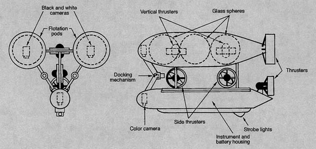
Box 2-3 AUV Example: ABE Woods Hole Oceanographic Institution built ABE, the autonomous benthic explorer for deep, near-bottom seafloor surveys. In 1995, ABE completed a geophysical survey on the Juan de Fuca Ridge at 2,200-meter depth, including magnetometer, conductivity, temperature, depth (CTD) instrument, and video survey. ABE has the ability to dock to a mooring and remain in "sleep" mode to perform preprogrammed, repeatable seafloor measurements over extended periods.
 |
National Aeronautics and Space Administration (NASA) research with undersea vehicle development (Stoker, 1994).
OPERATIONAL ATTRIBUTES OF VEHICLE SYSTEMS
Each type of vehicle has inherent attributes that make it more suitable for certain tasks than are other systems. Because of their stability and ability to provide direct viewing for occupants/operators, DSVs are very good for observation and most work tasks requiring manipulators and samples. However, because of their limitations of range and time on bottom or in the water column, which is dictated by the on-board energy source, human endurance, and the cost of support ship and crew, DSVs generally are not well suited for large area search and survey or extended observation—tasks that are most efficiently carried out by towed vehicles at present.2 Furthermore, because of their human occupants,
TABLE 2-2 Current Undersea Vehicle Capabilities
|
Vehicle Functions |
Requisite Characteristics and Capabilities |
DSVs |
ROVs |
AUVsa |
|
Reconnaissance |
Forward observation, search, measurements |
Good |
Good |
Good |
|
Local survey |
Small area observation and measurement, precise navigation |
Good |
Good |
* |
|
Broad area survey |
Large area (up to 300 sq km) observation and measurement, medium geodetic or relative navigation accuracy |
Limited |
Limited |
* |
|
Waste site monitoring |
Specific site observation, sensing, and water sampling |
Good |
Good |
* |
|
Mapping |
Terrain feature survey, tied to accurate geodetic navigation, larger areas |
Poor |
Limited |
Good |
|
Search |
Relatively large area coverage, acoustic and optical sensing, object identification, good navigation |
Good |
Limited |
* |
|
Inspection |
Close-up observation, optical and other sensors, good vehicle positioning and stability |
Good |
Good |
* |
|
Observation |
Similar to inspection, but implies real-time witnessing of dynamic events |
Good |
Good |
Poor |
|
Work |
General tasks involving vision, object manipulation, and use of tools |
Good |
Good |
* |
|
Sediment sampling |
Specific work task involving collection of material, including coring |
Good |
Limited |
Limited |
|
Installation/Retrieval |
Placement or recovery of objects and instruments in/from specific locations |
Good |
Good |
Good* |
|
|
|
|
|
Limited |
|
Accident investigation |
Observation, local area search, collection of material evidence |
Good |
Good |
Limited |
|
Waste disposal |
Transport and placement of toxic materials in predetermined locations. May be large quantities or a deep site. |
Poor |
Good |
Poor |
|
Water quality measurements |
In situ sampling and analysis in varying depths and locations |
Good |
Good |
* |
|
a Asterisks indicate that, while current AUVs are not suited to these tasks, developments are under way that could improve system capabilities to the point that the vehicle system should be suitable for the application. |
||||
DSVs are not suitable for operating in dangerous areas, such as in tunnels or around explosives.
ROVs, which are powered from the surface, have no real energy limitations. They are also generally stable. Viewing facilities for the human operator are good and continue to be improved, including stereo and new "augmented reality" compatibility.3 Hence, ROVs are inherently suited for working for extended periods, performing local surveys, operating in high-risk areas, and passing large quantities of real-time sensor information back to a surface support vessel. However, due to tether drag, ROVs are limited in how far and how fast they can travel from their support craft, and they are less suitable for large area, long-range search or survey and long, under ice transits.
AUVs can move rapidly and, subject to limitations of the on-board energy storage, can generally traverse great distances relative to the other two types of vehicles. This makes them well suited for transporting sensors over large areas for surveys of various kinds. Some AUV systems have used a fiber-optic communications link for all or part of their operation. However, this is not a routine mode of operation, and, without a tether, the communication mechanisms for real-time human intervention are limited. Nevertheless, the narrow beam acoustic links have passed at least 50,000 bits per second (bps), and even low-bandwidth links can pass some useful data. To extend the range of AUV applications, increasingly effective autonomous work systems are evolving rapidly along with the general field of robotics. Another present AUV limitation is that data transfer must wait until the AUV vehicle is recovered on-board a mother ship. In response to this problem, acoustic telemetry schemes now emerging offer a hybrid arrangement where the human can intervene on a limited, non-real-time basis. New advances in task-level control architecture will enable the operator to command tasks at a high-level in real-time (within the new bandwidth). AUVs are limited by the current lack of maturity of task-management architecture that can be placed on-board. Overcoming this limitation is the focus of present research at the Monterey Bay Aquarium Research Institute (Wang et al., 1993; Marks et al., 1994a; Wang et al., 1995).
Table 2-2 summarizes the foregoing discussion and includes a list of generic tasks that may be performed by vehicle systems. The committee has characterized the relative abilities of the different vehicle types to carry out these tasks; several qualitative descriptors are used, each representing the collective opinions of the committee and each based on considerations such as those discussed above.
EVALUATION OF THE STATE OF TECHNOLOGY
This section evaluates the state of the art and state of practice for vehicle technologies and assesses the potential for future developments. In the total system context described
earlier, vehicle technologies are discussed here in relation to the various subsystems that are common to all subsea vehicles. The technologies described are typically applicable to several if not all types of vehicles covered in this report. This section groups the subsystems into two categories: those that directly support vehicle operations, that is, energy, propulsion, and control; and those that are related to payloads to support various missions, that is, sensing, survey, and manipulation. These two categories may overlap in some cases, but the distinction is useful for analysis. New developments with near-term usefulness are cited for each area, and the status of synergistic technology developments from other industries is discussed.
Vehicle Subsystems
Each subsystem and its driving technologies play a role in overall vehicle performance and contribute to the vehicle's capability to accomplish specific mission objectives. Lack of development in certain technology areas inhibits progress and further applications because they determine or facilitate vehicle capabilities. The technologies in other subsystems are highly developed, and further advancement will not appreciably improve the overall performance of the system. Accordingly, during the committee's evaluation, each subsystem was given an importance rating of "critical," "incremental," or "mature," depending on our evaluation of its impact on further vehicle development. These ratings are characterized as follows:
-
Critical—Improvement in the subsystem will enable or create important new vehicle capabilities.
-
Incremental—Vehicle progress can benefit from development of subsystems technologies in an evolutionary manner.
-
Mature—Development has been successful and further improvement may occur, but development will contribute only marginally to improved vehicle performance, and improvements will be used only if they are cost-effective compared to current techniques.
Energy
Existing energy sources pose limitations for systems without cable connections (i.e., DSVs and AUVs), affecting system size, payload, and endurance. Energy limitations on AUVs are critical, and they are becoming more critical for DSVs because of the growing power demands of sensors, lights, computers, and manipulators. High-energy density batteries could lengthen missions and generally improve performance.
Energy sources are rated in terms of both energy and power. The most frequently used ratings are "specific energy" (watt-hours per kilogram) or "energy density" (watt-hours per liter). Batteries are usually used in underwater vehicles; numerous other energy technologies are also available, but they are more costly. The performance characteristics of available energy sources are compared in Table 2-3. The table is divided into four types of energy systems: secondary batteries, primary batteries, fuel cells, and heat engines. Secondary batteries are electrically rechargeable, while primary batteries are used for only a single cycle. (Ag-Zn may be included in either category; in its primary configuration it may be recharged as many as five cycles, which hardly counts as rechargeable.) Fuel cells are electrochemical devices that passively (without heat) react a fuel and an oxidizer to produce electricity; power levels are controlled by the amount of reactant injected into the cell. Many fuel cells are rechargeable, but not in the same way as secondary batteries; instead, reactant tanks are filled, and in some cases sacrificial metallic elements are replaced. Heat engines are generally closed-cycle, air-dependent systems that react fuel and oxidant in a mechanical cycle to drive an engine, which in turn directly drives the propulsion system or a generator to support electronic equipment. Table 2-3 is not intended to be all-inclusive. Instead it provides an overview of available energy technologies that can be considered for undersea vehicles.
Battery and fuel cell technologies developed for applications in space, automobile, and communications industries have not been adapted for use in undersea vehicles because of their cost, safety, immaturity in development, or incompatibility with marine missions. Cost is a primary factor and, as shown in Table 2-3, varies by orders of magnitude for different systems. Cost roughly increases as the energy density increases. For commercial AUVs and DSVs, the most advanced, high-energy systems are presently out of economical reach. These types of energy sources are found mostly in military systems where mission and endurance are primary factors that outweigh cost.
Factors important in selecting a battery include power density (the ability to deliver stored energy at the rate needed), outgassing properties, failure modes, reliability, ease and speed of recharge, and ability to operate over broad temperature and pressure ranges. Considerations of safety in handling energy sources, both aboard ship and aboard the vehicle, are critical and have limited the use of some chemistries, such as lithium, despite their high energies. (Some systems give off explosive gases during operation, and others may start fires if they fail.)
Current battery types used in undersea vehicles include standard lead-acid and nickel-cadmium batteries as well as silver-zinc and lithium-thionyl-chloride batteries. Figure 2-2 provides a helpful way to visualize the power and energy capabilities of various battery chemistries. For military applications, silver-zinc has been the de facto standard for over 20 years. Recently lithium-thionyl-chloride (see primary lithium in Figure 2-2) has seen some use because of its significantly higher energy rating. However, both silver-zinc and lithium-thionyl-chloride batteries are quite expensive ($300 to $1,000/kWhr) and have high life-cycle costs. Silver-zinc batteries are typically usable for 20 to 30 cycles,
TABLE 2-3 Performance Characteristics of Available Energy Sources
|
|
ASSESSMENT OF ENERGY TECHNOLOGIES FOR USVs |
|||||
|
Technology |
Specific Energy Wh/kg |
Energy Density Wh/Liter |
Cycle Life |
Cost $/kWh |
Maturity for Undersea Vehicles |
Safety Concerns |
|
SECONDARY BATTERIESa |
|
|
|
|
|
|
|
Lead Acid (Pb/Pb0) |
35 |
90 |
800 |
50 |
Proven |
H generation |
|
Nickel Cadmium (NiCd) |
55 |
130 |
1,000 |
1,500 |
Proven |
Cd toxicity |
|
Nickel Hydride (NiH2) |
60 |
150 |
10,000 |
2,000 |
Proven |
High pressure H |
|
Nickel Metal Hydride (NiMH) |
70 |
175 |
300 |
50 |
Proven |
High pressure venting |
|
Silver Zinc (Ag-Zn) |
140 |
380 |
20 |
1,000 |
Proven |
H generation |
|
Silver Iron (Ag-Fe) |
150 |
200 |
200+ |
500–800 |
Demo |
H generation |
|
Li-Solid Polymer Electrolyte (Li-SPE) |
150 |
360 |
200 |
100–1,000 |
Lab |
Lithium fire |
|
Lithium Ion Solid State (Li-Ion-SPE) |
150 |
360 |
1,000 |
100–1,000 |
Lab |
None |
|
Lithium Ion (Li-Ion) |
200 |
200 |
2,000 |
500–1,000 |
Proven |
Venting |
|
Lithium Cobalt Dioxide (LiCoO2) |
220 |
300 |
50 |
1,000 |
Lab |
Pressure venting, Li fire |
|
PRIMARY BATTERIES* |
|
|
|
|
|
|
|
Lithium Sulfur Oxide (LiSO2) |
140 |
500 |
1 |
400 |
Demo |
Li fire |
|
Silver Zinc (Ag-Zn) |
220 |
400 |
5 |
3,000 |
Demo |
H generation |
|
Lithium Manganese Dioxide (LiMnO2) |
400 |
450 |
1 |
200 |
Proven |
Li fire |
|
Aluminum-Seawater |
450 |
400 |
1 |
100 |
Demo |
N/A |
|
Lithium Thionyl Chloride (LiSoCl2) |
480 |
500 |
1 |
300 |
Demo |
Thermal runaway |
|
Lithium Carbon Monofluoride (Li(CF)x) |
800 |
1,200 |
1 |
1,700 |
Proven |
Li fire |
|
FUEL CELLS |
|
|
|
|
|
|
|
Alkaline |
100 |
90 |
400 |
5,000 |
Demo |
Gaseous H and O fires |
|
Proton Exchange Membrane (PEM/GOX/GH) |
225 |
200 |
50 |
10,000 |
Demo |
Gas H and O fire |
|
Proton Exchange Membrane (PEM/LOX/LH) |
450 |
400 |
50 |
15,000 |
Lab |
H and O fires |
|
Proton Exchange Membrane (PEM/SOX/SH) |
1,000 |
883 |
50 |
5,000 |
Lab |
N/A |
|
Aluminum-Water Semi-cell (A1/H2O/LOX) |
1,200 |
800 |
1 |
10,000 |
Demo |
H and O fire |
|
HEAT ENGINES (Closed-Cycle Air Independent Propulsion Systems) |
|
|
|
|
|
|
|
Internal Combustion Engine |
75 |
170 |
2,000 |
50–100 |
Demo |
Fuel fire |
|
Diesel Engine |
125 |
75 |
1,000 |
100–200 |
Demo |
Fuel fire |
|
Brayton-Lithium Sulfur Hexafluoride (LiSF6) |
400 |
700 |
1 |
15 |
Demo |
Fuel fire |
|
Stirling |
200 |
250 |
2,000 |
50–100 |
Proven |
Fuel fire |
|
a Battery parameters are based upon single cells; non-battery performance parameters are system level. |
||||||
and lithium-thionyl-chloride batteries are primary batteries (not rechargeable). The higher energy batteries hold the potential for violent release of energy under certain circumstances and are not generally used in commercial and scientific applications (Harma, 1988; Moore, 1988).
Although higher energy systems are critically important to high-endurance AUVs, cost and safety must be primary objectives as new sources are developed. Newer secondary lithium chemistries hold the promise of reasonable production cost, high numbers of recharge cycles (approaching the lifetimes of lead-acid automobile batteries), no outgassing, benign failure modes, and energy densities better than offered by silver-zinc batteries. Development of these batteries is largely being driven by laptop computer and portable electronics applications, but they are presently being adapted to larger-scale batteries for automotive use and should be available for military and commercial undersea vehicles within three to five years.4
Recharging techniques for secondary batteries are being developed for a variety of user applications in the telecommunications, automotive, and undersea vehicle industries. The intent is to reduce the recharge time, extend the ratio of operating to charging time, improve battery cycle life, and promote personnel safety. Charging techniques such as pulse charging can be used to manage the recharge process and decrease recharge time, to reduce heat generation, and to minimize cell degradation. For undersea vehicles, some new
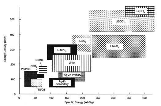
FIGURE 2-2 Battery cell comparisons. Source: Lockheed Martin Corporation.
lithium chemistries that emit little or no gas during charge and discharge are attractive because they can be charged in place (without recovery or vehicle disassembly). Other charging schemes include charging with solar cells, either by surfacing or by connecting to a subsurface charging station powered from the surface.
Other energy system developments include seawater batteries, which react metals with the oxygen dissolved in seawater. These batteries have been difficult to use because they produce very low- voltage and power due to the limited quantity of dissolved oxygen in seawater. However, efficient dc-to-dc conversion can overcome some of these limitations. Since seawater batteries depend on dissolved oxygen, these batteries also may not be suitable in some parts of the ocean, such as in hypoxic areas (Blase and Bis, 1990). Military research and development efforts have explored using seawater batteries, but little work is ongoing in this area in the United States. The Norwegian Defense Research Establishment has built and successfully tested a long-range (approaching 1,800 km) AUV that employs magnesium seawater batteries with a specific energy of over 540 Wh/kg (Apel, 1993; Zorpette, 1994).
Metals can also be reacted with oxygen carried on-board a vehicle. An aluminum-oxygen semi-fuel cell has been built and tested at sea with some success (Collins et al., 1993; Walsh, 1994). ARPA is developing a higher power density version (Gibbons et al., 1991) of this type of cell that contains a chemically stable anode (aluminum), works at low temperature, and has environmentally benign byproducts, mainly Al2O3. The key concerns in this technology are oxygen storage and manufacturability. Canadian companies have also developed an aluminum semi-fuel cell, which uses pumped alkaline electrolyte and oxygen sources. This energy subsystem has been tested in an AUV (Stannard et al., 1995).
NASA has used alkaline fuel cells widely in spacecraft for over 20 years. One of these fuel cells was successfully demonstrated in a DSV in the late 1970s; however, cost and logistical problems limited further development for undersea use. ARPA is now evaluating a proton exchange membrane fuel cell (Meyer, 1993; Pappas et al., 1993). In this concept, stored hydrogen and oxygen are reacted in a fuel cell with the potential of rechargeability and specific energies of over 600 Wh/kg. The newer proton exchange membrane fuel cells offer many advantages over alkaline fuel cells, including lower cost, higher power capacities, improved tolerance to impurities in the reactant gases, and better long-term cycle performance. Energy capabilities of fuel cells are high, but they are limited by the difficulty of storing hydrogen and oxygen at high densities. To achieve truly high specific energies in fuel cells (>1,000 Wh/kg) practical cryogenic (liquid oxygen) storage and solid hydride fuel are required. The logistics of reactant handling and storage continues to make cost reductions and practical usage of fuel cells elusive.
Isotope-based systems and small nuclear reactors have been proposed as ultrahigh energy sources (10,000 to 50,000 Wh/kg) for AUVs; however, these have not been implemented due to regulatory and cost restrictions.
Closed-cycle heat engines are another potential high-energy source for AUVs and DSVs. These can use conventional or hydrogen fuels in combustion cycles (e.g., Diesel,
Brayton, Stirling) similar to engines developed for the transportation industry. A Stirling engine was tested successfully in an undersea vehicle by a Swedish company and is operational on-board the French Saga vehicle.
The Office of Naval Research (ONR) has been pursuing improved thermal engines for torpedo propulsion for years. They have performed significant work in wick combustors, using liquid lithium reacted with sulphur hexaflorate to create a high-temperature heat source for a Rankine or Stirling thermal engine (Hughes, 1995). In an attempt to achieve a more environmentally benign, refuelable, high-energy density product (which is 80 percent of the energy generated by liquid lithium), the Applied Research Laboratory at Pennsylvania State University is investigating a wick combustor fueled with JP-5 (standard Navy jet fuel) and a lithium perchlorate oxygen source to drive the heat engine (Hughes, 1995). If successful, this approach may provide a less costly power source for AUVs in the future.
Most research and development in the field of energy storage occurs outside the undersea vehicles area. The committee anticipates that future energy system development applicable to undersea vehicles will derive mostly from the aerospace and automobile industries, where batteries and fuel cells are being evaluated for near-term use, and from the telecommunications and personal computer industries, where small-format lithium batteries are in development.
Energy systems are a low development priority for ROVs, whose performance is limited by other considerations. However, size, cost, and duration limitations related to DSVs and AUVs will be mitigated only when practical, safe, and readily available energy sources are developed. The advisability of making large investments in energy system research and development for commercial applications is questionable, and the decision must be made in the light of true development costs. Since most near-term AUV and DSV applications can be accomplished with existing and proven battery chemistries, research and development funds will be better spent in technology areas that are specifically marine, such as underwater navigation, acoustic communications, or subsea sensors. Energy systems will be advanced by industries such as the space, automotive, and telecommunication industries that have a more immediate need for them and can obtain development capital based on large markets for their products.
Propulsion
Most undersea vehicle thrusters now use fixed-pitch propellers driven by electric or hydraulic motors. The propeller configurations used derive from mature technology developed for ships and boats. However, optimization of propeller efficiencies continues as new undersea vehicle designs emerge. Brushless motors are often used for low-cost ROVs and most AUV applications. Heavy duty ROVs at work in the offshore petroleum industry use hydraulic motors to power thrusters; power is supplied from an electrohydraulic unit mounted in the vehicle. The pumps, motors, and valves used in system integration are largely standard commercial products. Because of high propeller loading, DSV and ROV thrusters are frequently mounted in nozzles to improve efficiency. If nozzles are used on AUVs, they usually serve as propeller guards rather than as thrust enhancers.
Other thruster types, such as variable pitch propellers, cycloidal devices, and water jets have been abandoned because of complexity or inefficiency (Gangadharan and Krein, 1989). Oscillating foils, which function like a fish tail, are being studied and have achieved limited drag reduction (Triantafyllou et al., 1992). This concept may be applicable to AUV propulsion in the future.
Another interesting new direction in propulsion for long-distance observations is using controlled buoyancy or combinations of buoyancy and thrusters to propel undersea vehicles. The "Slocum" for example, is a concept that would use a heat engine, drawing on the ocean thermocline to adjust the buoyancy of an AUV; wings would provide lift and limited horizontal steering (Kunzig, 1996; Stommel, 1989). The concept offers the promise of low-cost (tens of thousands of dollars, per vehicle, rather than millions); long-range (2,000 km as a near-term goal); and increased endurance (50 days). The ultimate goal is to offer a fleet of low-cost, long-range AUVs that would operate simultaneously, taking oceanographic measurements with higher spatial and temporal resolution than are available with current techniques and at substantially lower costs. (The Odyssey vehicle, described in Chapter 1, is another low-cost vehicle that could be deployed in fleets, although it has a shorter range.) The Slocum buoyancy-adjustment mechanism (without lift or steering) has been tested at depths to 1,300 meters. The system currently being developed uses a battery-powered pump to enhance buoyancy control and propulsion (Webb, 1996).
Propulsion systems are a mature technology and a low priority for development since existing systems are adequate—although improvements in efficiency are always useful—for most underwater vehicle applications anticipated in the next decade.
Materials and Structures
Structural materials currently used for DSVs, ROVs, and AUVs have been adapted from the submarine and shipbuilding industries as well as from advanced aerospace programs. Design approaches derive from work by ship classification organizations, such as the American Bureau of Shipping, as well as from finite-element analysis techniques used in naval architecture and in many industries. Thus, with the exception of full-ocean depth vehicles (11,000-meter depth capability), materials and design capabilities can be considered relatively mature. Improvements in materials tend to be more important for vehicles intended for deep applications because of the strength required to counter high pressures.
Improvements in material are also important for applications to AUVs, where lightweight materials can be translated into energy and payload for additional range and endurance and for work or sensing capabilities that require energy.
Currently, nonmetallic materials, including filamentwound epoxies, Kevlar, and graphite composites and ceramics, are used for military applications in both primary structures (pressure hulls) and secondary structures (fairings). However, the cost of some of these materials discourages commercial use. The Navy's AUSS uses graphite reinforced plastic/epoxy for its main pressure vessel, but the future of such materials in pressure vessel applications remains unclear, primarily because of difficulties in manufacturing processes and high cost (Stachiw and Frame, 1988; Stachiw, 1993). Ceramic alumina cylinders have been tested for pressure housings and hulls, with potential weight reductions of 85 percent compared with titanium; however, economical manufacturing techniques are still under development (Stachiw, 1992; Kurkchubasche, 1992, DeRoos et al., 1993). Other ceramics being considered include silicon nitride, silicon carbide, and boron carbide materials (Ashley, 1993).
Advanced materials for fairings include graphite epoxy layup or fiberglass constructions using a fiber-impregnated, high-density polyethylene that is also acoustically transparent (Sloan and Nguyen, 1992). AUSS uses this polyethylene material for its fairings. Advances in high quality acrylic and quartz glass will provide greater visibility to pilots of DSVs. Developments in important materials technology for vehicles aim to provide low-cost, lightweight, high-buoyancy materials for flotation. Sandwiched composite and syntactic buoyancy materials are being used to provide lightweight, high-displacement secondary structures. Although strength, density, and buoyancy are key design factors, longevity, corrosion resistance, and reliability also affect materials selection.
Design innovations have been demonstrated during development of new structures despite the relative maturity of conventional technology in this field. The two Deep Flight vehicle prototypes for a single-occupant, free-flying, full-ocean depth DSV represent an innovation in alternatives for supporting human activity in the deep sea (Hawkes and Ballou, 1990; Ashley, 1993). Deep Flight's pressure hulls are wound glass filament and epoxy matrix. Such a vehicle depends on advanced materials for structures to support its performance goals.
Russian and Ukrainian undersea vehicle programs have developed advanced techniques for fabricating structures of titanium, ceramic, and composite materials, according to two teams of experts who recently surveyed the undersea vehicle programs of western Europe and the former Soviet Union, under the auspices of the World Technology Evaluation Center (Mooney et al., 1996; Seymour et al., 1994).5 (Appendix B reviews the status of foreign undersea vehicle programs throughout the world.)
Another materials technology area of importance to system improvement is using coatings and other methods to resist biofouling or degradation of the vehicle's outer skin. Biofouling can create dynamic drag and interfere with the performance of skin-mounted sensors. This can be an especially critical problem for long-duration missions. Conventional coating systems that are used on surface ships may not be desirable for vehicles because the toxic compounds they use to kill organisms might cause chemical contamination of the vehicle's scientific sensors.
Navigation and Positioning
The success of most undersea vehicle applications depends on accurate navigation and positioning. Navigation is the function that continuously locates the vehicle within geodetic or relative coordinates and is critical to vehicle safety, operational productivity in real-time, and post-mission scientific and information processing. Positioning refers to the localized and more precise measurements often used to determine specific distances relative to some fixed point. For example, vehicle work in the offshore oil and gas industry frequently involves precision measuring and positioning of equipment relative to installations on the seafloor. When operating a vehicle in a localized area, most contemporary navigation and positioning systems make use of acoustic transponders such as the long-baseline networks widely used in many types of deep water work. Systems of this type use bottom-placed transducers in array fields with typical transponder separations of up to 4 km and can offer accuracies of 1 meter at frequencies of 26 to 36 kHz. Recent developments in acoustic positioning include a high-frequency, high-accuracy system that determines the position of a vehicle with an accuracy of a few centimeters in a bottom-placed transponder field. Other systems, which utilize transducers mounted on the surface ship and a transponder on the vehicle (short baseline), do not require transponders on the seafloor. These systems are widely used for navigating vehicles relative to a support ship. Combinations of these acoustic systems are used to maximize the advantages of each for best navigational accuracy for specific environmental conditions.
Numerous other acoustic and nonacoustic sensor technologies are used on the vehicle to enhance navigation and positioning. Simple video cameras are useful, especially for ROVs and DSVs, when operating near the bottom of a structure and can provide the operator a reference for motion. Computerized image processing techniques have been developed that can use information from video cameras to navigate vehicles automatically (Wang et al., 1992; Marks et al., 1994a, 1994b). Further developments of this type will enhance the value of video as a navigation aide, especially for AUVs, where precise autonomous, near-field navigation is
still under development. Other optical sensors such as laser imaging distance and ranging (LIDAR or laser radar) and line scanning lasers are becoming useful for short-distance ranging and imaging and have recently been developed in low power versions (< 200 watts) that will permit their use on AUVs and DSVs.
Scanning or multibeam sonars are used to provide operators with images of obstacles and terrain in the immediate area surrounding the vehicle. These systems are very popular and have developed to the point that high-frequency, high-resolution systems are reliable and economically available on the commercial market. Current developments in sonar and signal processing include obstacle-avoidance sonars that can construct a terrain map and guidance strategies for optimum pathfinding.
Navigation over long distances or for prolonged durations is generally a requirement for AUV missions and is critical to mission success. AUV navigation systems typically use magnetic or gyro compasses and a velocity sensor to provide dead-reckoning.6 Inertial navigation systems, aided by Doppler sonars, are an advanced implementation of this technique. These systems, derived from extensive use on aircraft and spacecraft, provide inertial navigation, which is then corrected by velocity estimators and by position fixes, as available. Estimated vehicle speed is obtained from current and flow sensors, Doppler sonars, or correlation sonars. Doppler sonar uses reflected echoes to provide highly accurate measures of motion relative to the bottom or fixed points in the water column. Similarly, correlation sonars accurately (+/- 0.1 kt) measure speed relative to the bottom (Grose, 1991). Doppler correlation sonars can "bottom-lock," referencing the vehicle's motion to the bottom, from altitudes of 3,000 meters or more. The advent of small inertial devices, such as ring laser gyros (a solid-state version of the conventional rotating gyro), are making this type of navigation increasingly useful as accuracy goes up and cost goes down (Moore, 1991; Ezekiel, 1991). The result is that velocity-aided inertial navigation systems are now available that provide accuracies on the order of 0.1 percent of distance traveled, and further improvement will result from integration with better location and true movement sensors. As these improvements continue, costly, time consuming transponder fields will become increasingly unnecessary.
The greatest advances in undersea navigation in the near future will come not from any one isolated type of system but from integration of an increasing number of systems and components. Most of the above techniques benefit greatly from position referencing to the Global Positioning System. Recent work in the combination of inertial units with ultrashort baseline transponder systems and Doppler sonars has shown that combining sensors with different characteristics can synergistically improve navigation performance (Hutchison and Skov, 1990; Hutchison, 1991). Accuracy on the order of 0.05 percent of distance traveled are achievable with inertial navigation systems and Doppler sonars, which are becoming available at moderate cost.
Guidance and Control
Navigation, guidance, and control functions are often separated for discussion, as is the case in this report. This modularization assists in understanding the complex operating concept for undersea vehicles and is also helpful to the vehicle designer. In practice, however, these functions are highly interactive and, in fact, use many common sensors and processors. Thus advances or improvements in one function normally are linked to advances in other functions. For example, the development of a highly accurate, long-duration navigation system would be useless without guidance and control capabilities that support mission intelligence and reliable navigational capabilities.
Guidance and control of an undersea vehicle are generally implemented in a layered or hierarchical architecture. Guidance involves higher-level mission management activities, such as planning and directing vehicle movement through the water column; control operates at a lower functional level to interact with specific equipment on the vehicle. The control level includes the closed loop functions (autopilot) that provide stable, controlled operation of the vehicle. The control level receives orders from guidance and, in turn, commands physical actuators, propulsors, and effectors to maneuver and operate the vehicle in a manner that accomplishes higher-level guidance objectives.
In the early days of undersea vehicle development, maneuvering depended almost exclusively on the direct manual control skills of human pilots, and all higher-level planning was accomplished by the pilot. With ROVs, pilots worked primarily from video images, using visual references to keep track of vehicle and tether location. Later, automatic heading and depth controls became common on most vehicles because of the evolution of reliable sensors, modern computing equipment, well-understood control algorithms, and efficient software. Tracking systems, imaging sonars and inertial navigation systems also improved the human operator's ability to determine vehicle position in geodetic or local reference coordinates, thus enhancing vehicle guidance and control.
Continuing improvements in navigation and control technology permit automation of all vehicle motions. A vehicle with full automation and control of movement and direction can hover for long periods and can follow preplanned track lines precisely while under "supervisory control," that is, with the human operator providing high-level, task-oriented commands rather than exercising direct control over all functions of the vehicle (Yoerger and Slotine, 1987; Wang et al., 1993). Vehicles equipped with such capabilities have
performed detailed, three-dimensional scientific surveys of archaeological sites and deep ocean hydrothermal vent plumes, dam and nuclear reactor inspections, "hands-off" docking on oil field structures, and automated operation of valves (Somers and Geisel, 1992). Techniques are also being developed to allow vehicles to hold position based on video, laser, and acoustic imagery and to use imagery for guidance (Marks et al., 1994a, 1994b; Negahdaripour, 1993; Wang et al., 1992). Many advances in control depend on improved understanding of vehicle dynamics and improved signal processing algorithms for closing feedback loops around sensors to form servo loops (Yuh, 1990; Healy and Leonard, 1993; Fossen, 1994).
Future developments may extend these capabilities in several directions. Improved navigation that combines inertial and velocity measurements (as described in the previous section) currently being developed for military AUVs will enable precise automated vehicle motion without the need for a transponder network. Control systems combined with sensors that detect cables, pipelines, hydrocarbon leaks, or other pollutants allow highly efficient automated tracking and surveying (Greig et al., 1992). Likewise, improvements to in situ sensors for oceanographic parameters and chemical samples, combined with advanced vehicle control systems, will allow scientists to map distributions with unprecedented sampling density at reasonable cost, perhaps with multiple vehicles (Triantafyllou, 1992; Curtin et al., 1993). At the heart of these improvements is the ability to integrate navigation, guidance, and controls with sensors, using modern hierarchical architecture techniques to enhance accuracy, efficiency, ease of human task-level control, and reliability of vehicles for a wide range of mission needs.
A significant step toward achieving these integrated goals was demonstrated in a series of 13 dives over the Juan de Fuca Ridge by MIT's AUV Odyssey II. Odyssey II reached a depth of 1,400 meters and ran surveys designed to characterize spatial variability of temperature and salinity in three dimensions. Navigation was provided by a long-baseline acoustic navigation system. In a 3.25-hour dive, the vehicle excursions centered on a thermocline at 45 meters beneath the sea surface. To provide an understanding about temporal evolution in the survey volume, the grid survey was preceded and followed by vehicle paths crossing the survey volume.7
As indicated above, developments in guidance and control, at all levels, are critical for progress in AUV applications where robust mission management is key to reliable and repeatable performance. Artificial intelligence techniques are being applied to offer AUVs an interpretive logic capability based on processing probabilistic data.
In the future, AUVs should be capable of pursuing tasks that have abstract descriptions; for example, finding and following a chemical gradient or surveying a given area with the ability to replan and reconfigure the mission based on a wide range of changing internal and external factors. Included in these tasks are a number of lower-level operations, including obstacle avoidance, homing and docking, and following terrain, as well as manipulative tasks that involve control of the vehicle/manipulator system to carry out a command.
Failure detection and recovery are perhaps the most critical operations and the most difficult. The vehicle must be able to sense when one or more of its subsystems have failed and must be capable of reconfiguring its controls and replanning the mission in real-time to work around in the worst case, aborting the mission in the safest manner. The the problems; accomplishing the highest priority objectives; and vehicle must also be able to handle high-level failures such as reattempting and Bellingham, 1992). "Layered control" is one approach to this problem. Vehicle software provides commands for a set of quasi-independent "layered" behaviors, such as "detect collision," "hold heading," or "head to way-point." Layered control has demonstrated some success a docking operation that fails the first time (Ricks, 1989; Perrier as an overall philosophy for AUV programming (Bellingham and Leonard, 1994). A Navy-sponsored project is developing an intelligent, fault-tolerant vehicle guidance and control system, and system testing and demonstration are planned. While much of this development is directed toward specific use by AUVs, it is supported by complementary work of the computer aerospace and automated manufacturing industries. Continuing advances in task-level control architectures and higher bandwidth communications have resulted in robots that respond directly to graphical task-level human input. These robots use an advanced form of "telerobotics," or control from a distance, which until recently allow only a "joy stick" human interface.
For many mid-water tasks the vehicle and its manipulators need to be controlled as a single moving system. The new capability called "object-based task-level control" enables the direct human command to the task that will be performed; the control system then plans and executes the task. Because of the much lower bandwidth required for task-level commands, object-based task-level central will enable near real-time control of AUVs, which will be a powerful new capability (Wang et al., 1993). Techniques for vehicle control are continuously being improved. Research and development activities are being directed toward adaptive systems that can successfully control a vehicle with widely varying characteristics (e.g., mass or hydrodynamic coefficients). The use of sliding mode controllers is one approach; another involves intelligent systems that estimate vehicle characteristics in real-time.
Improved guidance and control techniques can enhance the capabilities of ROVs and DSVs and are crucial to the success of AUVs. Improvements in fault tolerance can permit vehicles to complete missions after sensors, actuators, or processors fail or degrade. Another important direction for AUVs is to move beyond simple way-point control to permit the vehicle to pursue tasks from more abstract descriptions.
Data Processing
Undersea vehicles typically require two types of data processing, payload and vehicle- management. The payload processor collects, processes, compresses, and records the data produced by the vehicle and its sensors, often on disk in the vehicle itself or on a support vessel. The data are generally recorded during operations and processed afterward, especially in scientific applications. Data compression is essential when recording devices or the uplink bandwidth are limited and data volumes are large. The payload processor also can perform processing to augment and fuse the data that are collected; for example, the vehicle data can be matched to the image from a sonar, and the fused result gives an accurate picture of the situation encountered by the vehicle at a given time and place. The advent of fiber-optic communications and advanced sensors for ROVs has allowed transmission of large volumes of data up the tether for data logging, management, and display.
The second type of data processing is performed by the vehicle-management computer, which can be located on-board the vehicle or on a support vessel. These data may also be processed in real-time for use in decision making, such as for mine detection and target classification applications. The vehicle-management computer typically performs all the housekeeping functions necessary to keep the vehicle in motion along the prescribed path. The data can be used to control vehicle functions such as thrusters, control surfaces, valves, and manipulators in real-time. As the human operator becomes more removed from the vehicle control loop, and as tasks become more automated, the performance of vehicle-management computers becomes critical to mission success.
Another key issue in the data processing chain is calibrating the sensors used to make measurements and detecting a failed or faulty sensor. The vehicle-management processor must continuously monitor the sensor output for validity and presence. Sensor redundancy can help considerably in this process; however, deciding when a sensor has failed and when to switch to a backup sensor is a difficult process without an operator in the loop. In scientific operations using tethered systems, the sensor outputs are continuously monitored by the operations team, and the team decides whether to continue the mission or retrieve the system and initiate repairs. This process must be automated in AUVs; therefore, it is a critical area for improvement. Intelligent systems are currently being developed that will be able to monitor and compare sensor outputs. Upon detection of a failed sensor, these systems will make an informed decision about the goals of the mission and cause the vehicle to surface or continue depending on criteria that have been preprogrammed by the scientist or operator.
Developments in data preparation, fusion, presentation, and analysis are necessary to fully use and understand data collected by undersea vehicles. Fusion of many different types of data, including sonar, video, still images, water column measurements, and vehicle positioning data, must be available for scientific evaluation (Rosenblum et al., 1993; Gritton and Baxter, 1993). In the past, post-mission processing of data was performed by a human, who correlated photos, sonograms, strip charts, and computer data in a time consuming and not always accurate attempt to evaluate the vehicle's mission. Current advancements in post-mission processing, which incorporate simulation and display of the data collected from a mission using three-dimensional graphic software tools, aid the scientist in accurately reconstructing the mission and evaluating the data. Real-time map and chart construction fuses vehicle positioning, terrain, and targets encountered during a mission and allows faster evaluation of post-mission data (Howland et al., 1993). These techniques also aid the pilot and the observer in constructing a mental image of the subsea environment while they are working. Designers of vehicles for scientific applications will increasingly build data management into their basic design philosophies to make the data collected by undersea vehicles more useful and more easily understood (Newman and Robison, 1993).
Some help for vehicle designers may be provided by software systems designed for data processing in military applications. Current studies on the correlation of satellite telemetry and image data can be directly applied to the undersea world in the future. Commercial systems are also emerging that can handle diverse vehicle data. The new PC processors are now powerful enough to display complex data in real-time, complete with three-dimensional colorized representations of detailed images. Contemporary commercial software tools make plotting numerous pieces of data on multiple charts easier. New display techniques, including virtual presence, will further ease the task of understanding and interpreting data from the undersea environment by enabling scientists to position themselves aboard the vehicle and fly the mission, experiencing firsthand the situations surrounding the data as they are collected (Gwynne et al., 1992).
Enhancements in undersea vehicle capabilities are closely tied to advancements in microprocessors and computer science. In the past 10 years processing signals and managing underwater vehicle systems have progressed from implementing a single desk-sized minicomputer to incorporating many, in some cases hundreds, of printed circuit board processing elements. This improvement enabled major reductions in cost and size and has increased the availability of microcomputers that continuously improve in
terms of low power operation and computational through-put. The microprocessor boom, in conjunction with the shift toward distributed networks of specialized computers, has resulted in a revolution in processor system capabilities for undersea vehicles.
DSVs and ROVs have benefited from increased reliability of on vehicle data processing systems and advanced operator displays that are adaptable to various missions and operators. Miniaturization of control systems has allowed integrated operations of DSVs and ROVs, extending their combined capabilities beyond that of a DSV operating alone. Increased capabilities for storing and managing data aboard DSVs has also enhanced data integrity and accessibility for scientific applications. Underwater vehicles have also borrowed from advanced computer science in the move toward distributed processing of vehicle sensor information through "smart" sensors that are directly integrated with a microprocessor. This has the additional benefit of standardizing sensor protocols and message formats and increasing design simplicity for human applications. Data incorporation from multiple sensors through a single analog to digital converter has given way to on vehicle networks that extend through the data transmission system to the support platform to provide better displays of sensor information and increase reliability.
AUV missions are clearly the most computation-intensive of undersea vehicle applications; yet these are easily being implemented with current computational capabilities. Over the past decade, the computing revolution has resulted in order of magnitude increases in processor capacity every few years at continually reduced power levels. A central processor the size of a small loaf of bread, weighing under 4.5 kg and drawing less than 10 w, can implement all guidance, navigation, and control functions required by an AUV.8 Future AUV missions will demand the higher levels of on-board signal processing and data processing that are associated with increased levels of autonomy. However, it is expected that developments in semiconductor materials, improved board geometries, and more efficient operating systems for compilers will easily meet the computing requirements. In addition, the use of advanced paradigms, including artificial intelligence, fuzzy logic, and neural computing, is becoming more mature, and these paradigms will implement efficient sensor-based perception and data fusion for object interaction and advanced fault detection, isolation, and management.
Current work in signal processing is benefiting acoustic communications and sensor signal processing. The incorporation of low power, algorithm-specific processors with high processing rates provides the required through-puts for separating signal from noise and integrating signals into meaningful information. Advancements include distributed and parallel processors to interpret on vehicle acoustic, video, and laser imagery when evaluating objects in the environment.
Vehicle design, analysis, simulation, and verification, especially for AUV applications, have benefited from advancements in computational capability. Vehicle development and construction have progressed from empirical hand-drawn designs to completely computer-developed and maintained representations that can facilitate automated manufacturing. Analysis is enhanced through solid modeling and simulation that approaches real-time in complex tasks such as fluid flow and vortex analysis. At the far extreme of capability are the enhancements being made in ARPA's Simulation Based Design Program, which extend the current capability to allow three-dimensional virtual reality visualization of the vehicle and its subsystems, combined with physics-based modeling, to evaluate performance before physical construction.
As mainstream computing hardware and software evolve, these advances can be incorporated into underwater vehicles to make them more capable and reliable. In particular, techniques that combine diverse types of data will allow scientific and commercial data products to be produced more quickly, more cheaply, and with higher quality. In addition, automated techniques to monitor and manage sensors will be vital to permitting AUVs to produce high quality data sets without intervention.
Communications
Communication between human operators and the vehicle system—to receive control signals, report mission status, and transfer sensor data—encompasses several technologies, the use of which depends on the vehicle type. In general, AUVs use communication transmitted acoustically through water at 8.075 kHz and 27 kHz (operated half-duplex) as the most common frequencies. ROVs use an umbilical cable or link that contains coated, shielded, twisted-pair and/or fiber-optic members.
Communication capability with tethered vehicles (ROVs) has significantly improved with the transition from copper-based to fiber-optic-based systems. This advancement has closely followed developments in the telecommunication industry. The emergence of fiber-optic data transmission and communications technology has increased the capability of ROVs to pass enormous volumes of data through the tether for data logging, management, and display. As the volume rate and reliability of the data have increased, so has the data value to operators and users. It is now possible to tie sensor information regarding temperature and chemical composition, for example, to precise, specific locations relative to geological resources. The collection of sensor information and geolocation has also become critical in military mine countermeasures and explosive ordnance disposal applications.
ROVs generally require transmission rates greater than 1 megabyte for video and data channels, which is easily satisfied by twisted wire pairs in tethers of less than about 1,000 meters in length. Optical fibers, which are included in tethers for very long distances or for high transmission rates, exceed coaxial cable performance by several orders of magnitude, permitting the use of a large number of digital and video lines. At present, multimode fibers are used for umbilicals 1,000 meters to 3,000 meters in length, and single-mode fibers are used for longer umbilicals. Single-mode fiber-optics and associated electronic technologies are evolving rapidly, and it is likely that single-mode fiber-optics will become dominant in all umbilical lengths. In the fiber-optic communications system, data are passed along the umbilical by line driver receivers, laser diodes, and other off-the-shelf devices. Both digital and analog data streams are used, as are error-code checking strategies adapted from other applications.
Fiber-optics can be used for special vehicle applications, including providing a disposable telemetry link from the vehicle as it travels (Brininstool and Dombrowski, 1992; Grey, 1992). Distances in excess of 185 kilometers (100 nautical miles) are achievable without using repeaters. The difficulty of repair in the field has been a limiting factor in the proliferation of fiber-optic systems, but improvement in field maintenance is removing this constraint.
Except for special hybrid configurations, where fiber-optics are employed, autonomous tetherless vehicles cannot benefit from the advantages provided by fiber-optic communication links and must rely on the sound-transmission characteristics of the ocean. One of these characteristics, the speed of transmitting the acoustic signal, results in a lag between the transmission and receipt of the command data or signals, the resultant action, and the operator's perception of the effect of the action. This is a similar problem (but much greater in time scale) to the problem challenging tele-operations for the NASA Mars Rover Program. Long transmission delays are generally overcome by some level of autonomous behavior within the vehicle and supervisory control by the operator (for example, commands are given by the operator to pick up an object rather than transmitting detailed manipulator orders). This level of abstraction has come about only recently with the development of high-speed computers and microprocessors.
Although data flow via acoustic links is limited by the seawater medium to very low-bandwidths, using present technology and practice acoustic telemetry can carry control data and transmit image data from untethered vehicles or between networks of seafloor instruments and vehicles. Recent developments in signal processing and communications can be applied to exchange data at a reduced rate. Until recently, acoustic communications with submersibles has been limited to voice, such as the use of the underwater telephone. The range of this voice or Morse Code communication path is inversely proportional to the transmission frequency and limited by the transmission power. Acoustic communications have proven successful for long, straight paths in deep water (Mackelburg, 1991). In shallow water and with horizontal signal paths, however, the acoustic qualities of the ocean, combined with reverberations caused by reflections off the surface, seafloor, and other obstacles make the problem much more complex (Catipovic, 1990).
Current techniques for acoustic communications can deliver rates approaching 20,000 bits per second (bps) in deep water and about half that in the more difficult environment of shallow water at horizontal ranges. This technology is changing rapidly, especially for systems that communicate with free-swimming vehicles. Pioneering attempts at acoustic digital data communications were developed by the Naval Command, Control and Ocean Surveillance Center, San Diego, California, for use in supervisory control of the AUSS vehicle. The vertical communication path enabled transmission of command signals at a rate of 2,400 bps and freeze-frame video images were transmitted using data compression at a rate of 4,800 bps. The incorporation of computationally capable, low power, algorithm-specific signal processing by Woods Hole Oceanographic Institution and Northeastern University (Stojanovic et al., 1993; Stojanovic et al., 1995) has permitted significant improvements in digital acoustic communications, approaching a limit of approximately 3 bps/Hz. Catipovic has successfully demonstrated long-distance, shallow water communications at burst transmissions of more than 30,000 bps with a continuous through-put more than 8,000 bps out to approximately 3 km.9 The realization of these data rates allows for real-time acoustic transmission of data at significant baud rates to enable real-time vehicle control limited by the speed of sound through the water. A series of acoustic modems can then be used to control a vehicle in arctic waters (Bellingham et al., 1994) or to send data to a central collection buoy from a distributed network of ocean bottom sensors (Robison, 1994).
Acoustic telemetry has limited range by itself but can be combined with other types of telemetry to provide longer ranges. Other complementary types include satellite telemetry or cabled telemetry from seafloor acoustic installations. A vehicle could surface periodically to transmit data to low earth-orbiting satellites, although practical problems concerning vehicle stability, antenna design, and power consumption must be addressed. A vehicle could also communicate acoustically to a network of moorings, some of which are equipped with surface buoys and satellite links. Likewise, an AUV could communicate acoustically to a hardwired installation such as a seafloor observatory or other hydrophone array.
Significantly higher data rate transmissions can be achieved using pulsed lasers. An ARPA-sponsored project demonstrated 100 megabytes per second data transmission from an autonomous vehicle to a submerged submarine in 1992.10 The attenuation of light in the ocean, however, limits the pulsed laser range to approximately 100 meters or less.
An important area of communications for undersea vehicles is the use of satellite or radio frequency links. Both the Woods Hole Oceanographic Institution and the Monterey Bay Aquarium Research Institute have used this method to display science results from ROVs working offshore in real-time at the laboratories on shore. AUVs may also benefit from this technique by docking at subsea data transfer stations periodically to recharge batteries and transfer data for transmission ashore via surface buoys.
This is a very active field, drawing on advances in the electronics and telecommunications industries. Significant advances are also being made in sonars and acoustic sensors and in understanding acoustic oceanography. The impact on DSVs and ROVs will be incremental. However, as improvements are made in communication systems, especially acoustic links, and as the new systems become cost-effective, they will have a major impact on AUV performance capability.
Payload Subsystems
Payload systems are those carried by the vehicle to perform mission tasks. Payload requirements influence the design of the basic vehicle platform for specific missions. The challenge for the payload designer is to achieve the maximum system performance within size and energy consumption limits. Payloads systems include:
-
work systems (e.g., manipulators, end-effector tools, tool racks, and bins for storing samples)
-
sensor systems (acoustic, optical chemical radiation, gravity, and magnetic field sensors; fluourometers and transmissometers; and conductivity, depth, temperature sensors)
-
current meters
-
payload power systems (often separate from the main power system, so that a failure of payload power will not shut down the full system)
The number, size, and weight of payload systems affect vehicle size, mass, and propulsive power requirements. The number of energy-consuming payload systems helps determine the total energy system requirements; energy efficiency is important.
Work Systems
Manipulator arms are used on both DSVs and ROVs to accomplish common scientific and industrial tasks; manipulator development is likely to result in incremental increases in performance capability for these vehicles. Manipulator use an AUVs is still embryonic, but improvements could significantly enhance AUV capability for performing a greater breadth of operations. Current practice involves rate or master-slave manipulators, where the operator (located inside a DSV or on a surface vessel controlling an ROV) operates the arm by throwing switches or by moving a miniature version (the "master") of the manipulator on the vehicle (the "slave"). Typically, modern hydraulic arms on large ROVs can lift hundreds of kilograms, even when fully extended.
New control techniques drawn from space developments will allow the human operator to command directly at the task-level what is to be done with the object of interest, and the vehicle manipulator system will respond by carrying out that command. The operator needs no special "crane operator" skills, and a scientist or the field engineer can play the operator role. The operator can then focus completely, in real-time, on the task itself and the objects to be manipulated, whether they are science samples, cores, or equipment (Wang et al., 1993).
Manipulators need a device, called an "end-effector," to perform the actual task. End-effectors are often general-purpose hands or grippers, but they can also be special purpose power tools, such as drills, cutters, or wrenches, especially in offshore oil applications. These tools are often grouped into "tool packages" that allow the vehicle to use several different tools during one dive. Whereas formerly it was considered an accomplishment for an ROV to open and close valve handles on offshore platforms, new tool development now allows undersea vehicles to perform increasingly complex tasks in increasingly deeper water, including lubricating, pipe-cutting, making and breaking hydraulic connections, rigging support, and maintaining communications cable under water (Bannon, 1992; Gray et al., 1992).
Important tasks performed at mid-ocean depth, where capturing an object involves moving and controlling the vehicle and its manipulators as a single system, require more advanced capability. The new capability, "object-based task-level control," enables the human to command the task to be done; the control system then plans and executes the task, using the on-board vehicle manipulator control system. This capability will allow near real-time control of AUVs in mid-water tasks (Wang et al., 1993).
Scientific applications also require manipulators and tools, especially for selecting and gathering samples. New and diverse tools being developed for these tasks will continue to increase the scope of scientific work that undersea vehicles can perform. Nonetheless, general-purpose manipulators will always be important in undersea vehicle science. Current low-cost ROVs usually come with some basic manipulation capabilities, and their dexterity will improve to approach that of the larger systems, although their load capability will likely remain limited (Schloerb, 1992; Sprunk
et al., 1993). Vehicle manipulators can be improved and more sophisticated tasks commanded at the task-level with the development of new underwater sensors for proximity, force, touch, and audio—to give the operator feedback on the performance of manipulators and other mechanical systems—which will most likely be based on devices created for terrestrial and space applications.
The payload-carrying capabilities of vehicles are important for selecting or designing tool packages. More capacity means heavier tools capable of performing greater work; and, especially in geology, carrying capacity affects the ability to transport sample rocks to the surface.
More research and development needs to be done before AUVs will be able to perform more than simple tasks. However, there are several applications that could use even primitive autonomous recognition and manipulation. This is particularly important when the surrounding geometry can be controlled and anticipated, such as maintaining structures whose physical characteristics are well known or structures specially built for robotic maintenance. Work in outer space has had to deal with similar time delays and task structure problems to those that are faced in some AUV designs. Therefore, it is expected that useful techniques for accomplishing tasks will derive from space-related work as well as from subsea contexts (JPL, 1995). Projects to develop robotics applicable to undersea vehicles have been completed or are under way at NASA's AMES facility, the Stanford University and MBARI joint program (Wang et al., 1993), and the Pennsylvania State University and Woods Hole Oceanographic Institution joint program.
Sensors
An important undersea vehicle mission is collecting data from various types of sensors. Thus, sensors tend to be a technology limiter or driver for vehicle applications. Sensors in the context of "payloads" refer to those sensors that are not directly involved in the functioning of the undersea vehicle but are used to collect data from various external sources, such as the environment. Such sensors can be carried by all classes of vehicles; typically, the sensors are matched to the type of host vehicle that is transporting and supporting them. For example, sensors that are applicable to large area searches would not normally be installed on DSVs, which may have poor range and endurance capabilities. Furthermore, the characteristics of specific vehicle types can have a significant influence on the design of sensors. A case in point is AUVs, where sensors are critical to overall capability, particularly because of limitations to direct interaction by humans in system control. From a handling and cost point of view, a common desire is to make AUVs as small as possible, thus imposing payload-carrying capacity and resident-energy limitations. This, in turn, imposes similar restrictions on allowable sensors, which must be smaller and more energy efficient. If AUVs make possible longer missions than those of DSVs and ROVs, they will need sensors that are more resistant to fouling and with longer-lasting calibration characteristics. DSVs and ROVs will derive benefits from improvements in these same sensor characteristics.
Foreign work on sensors is exemplified by the European Community Cooperative Research Program, Marine, Science and Technology, which funds research and development in sampling and measuring instrumentation, including optical plankton analysis systems, electrochemical instrumentation for in situ determination of trace metals, in situ acoustic characterization of suspended sediment, and anti-fouling coatings for submarine sensors. Acoustic and optical sensors are the most broadly applicable and deserve the highest research and development priority.
Acoustic Sensors. Acoustic payload sensors include side-scan sonars and special scanning sonars, subbottom profilers, and imaging sonars. Side-scan sonars represent a well developed engineering practice, with advances primarily in the areas of processing and display, not the on-board transceiver. However, in the case of AUVs, significant efforts have been directed toward digitizing and processing side-scan sonar signals on-board the vehicle, either to conserve data storage space or to form the basis for autonomous action. Various types of scanning sonars can require significant on-board processing and may even contain their own processors. Synthetic aperture sonars, which promise to increase range and resolution by an order of magnitude, require very accurate navigation for short periods. If such sonars can be reduced in size and power consumption to be readily installed on AUVs, while at the same time meeting their navigation requirements, then all potential host vehicles will benefit. Acoustic imaging sensors have been under sporadic development for over 20 years. These sensors, which are useful even in murky water, have relatively high frequencies—on the order of 0.3-2.0 MHz—and can achieve image-level resolutions. Consequently, useful ranges are commonly limited to 100 meters or less. Scanning sensors have frequently been used on ROV systems for approximately 15 years. With a size reduction, these sensors can be installed and operated on some AUVs.
The trend toward processing acoustic data on-board as a director for vehicle action, without human intervention, has several direct benefits. One is to reduce time required to implement such action; another may be to assist a human operator. Algorithms imbedded in resident software can assist with specific object recognition for tracking animals or locating objects. This can be done by programming the resident acoustic sensor processor with the unique characteristics of objects to be recognized. When these characteristics are matched with the incoming sensor data, a specific action, such as a vehicle maneuver or an alarm, results.
A variety of acoustic sensors are available to study the distribution and abundance of animals in the water column.
Currently, there are three principal architectures used to count targets, estimate target strength, and estimate volume backscattering. Multifrequency systems use inverse techniques to estimate biological properties; dual-beam and split-beam echo sounders measure the properties directly. Recent research has demonstrated wide variation in scattering properties of zooplankton and micronekton (Greene et al., 1989, 1991, 1994; Wiebe et al., 1990). Developments in these systems will be vital to making accurate estimates of biological properties.
Optical Sensors. Video cameras are the most commonly used optical sensors. A number of camera technologies, including charge coupled devices (CCD) with one to three chips, silicon intensified target, low-light-level imaging tubes, stereo pair imaging, and CCD based electronic still cameras, have been adapted from their parent commercial applications for use on undersea vehicles. Sources for these technologies include the television industry and military systems. Because of the severe limitations on available energy in AUVs, low-light imaging sensors (which do not require power-consuming lights) are an important optical payload component.
Video cameras and high-speed strobes can be configured to provide high-resolution images of plankton at frame rates of up to 60 per second. Individual targets as small as 60 microns can be identified. Automated image analysis techniques are being developed, but considerable work remains to be done in this area. Sample volumes at the highest resolution are extremely small, and much higher capacity CCDs are required. Increased image sizes, however, will require new data compression schemes that reduce the data loading and significantly enhance low power data storage media.
As with acoustic perception capability, the real power of an artificial vision system is the perception capability that carries far beyond optical sensing per se. Providing a degree of scene analysis on-board the AUV makes it possible to send key information over the acoustic data link to the human task director in near real-time, which in turn enables the human to direct tasks in near real-time. For example, using newly developed bottom-mosaicing techniques, the AUV can accomplish local real-time vehicle guidance by scene matching. The scientist looking at the transmitted scene image can instruct the AUV to "hover over that starfish there," and the AUV will obey.
Other optical sensors that are emerging in development with direct applicability to undersea vehicles are the laser line scanner (LLS) images and range-gated laser imagers. LLS sensors work on the principle of a single laser, directed to scan a sector of the ocean bottom while the host vehicle moves forward at a uniform rate. The result is a good resolution waterfall (continuously scrolling) image display of much larger areas than conventional camera systems can cover in water of equivalent clarity. Recent enabling developments in LLS technology include the incorporation of solid-state lasers that require only 100 watts power and folded optics, that can reduce overall size by 50 percent. High sensor cost has restricted widespread use of the LLS to date.
Laser range-gating uses a traditional CCD image sensor, but "gates" the light reflected from a laser pulse to eliminate unwanted backscatter (Swartz, 1993). Unlike the LLS, which requires the vehicle to be moving to provide the second display axis, range-gated systems can be stationary, that permits precise positioning in the vicinity of an area of interest. Range-gated optical sensors have recently become available, and they have already undergone a tenfold reduction in required power and a significant size reduction; the cost remains high, however.
Chemical Sensors. Chemical sensors allow undersea vehicles to perform tasks that would otherwise require collecting water samples for laboratory analysis. It is necessary to distinguish between chemical sensors (devices in which passive diffusion transports the substance to be analyzed to the detector) and chemical analyzers (devices that actively transport the substance through an analytic process). Both types of devices can work on undersea vehicles.
Sensors are used to monitor dissolved chemicals. However, few chemical sensors with adequate sensitivity and selectivity are available today for the in situ determination of dissolved chemicals in seawater. Electrochemical sensors for oxygen and pH are the only devices that are in widespread use for in situ measurements. Changes in oxygen and pH reflect the rates of primary production (or respiration) through production of oxygen and consumption of carbon dioxide during photosynthesis. They do not provide direct information on the nutrient elements that limit these rates. Today, the only method for remotely monitoring dissolved nutrient or trace element (e.g., NO3, NH4, PO4, SiO2, Fe, Co, Mn, Zn) concentrations is to use fully automated chemical analyzers (devices in which mass transport moves the chemical through the instrument) that are adapted to operate in situ. Work on such devices is in progress at several laboratories, and it is now possible to monitor concentrations of nutrient species for extended periods of time (up to several months) with sensors appropriate for mounting on a vehicle. Such analyzers are based on the principle of flow injection and are inherently more accurate and complex than sensor systems. Recent advances have made it possible to produce systems with only a few moving parts (Johnson et al., 1986b; Jannasch, 1992). Analyzers also have the advantage of providing a direct, chemical calibration while operating in situ. Chemical analyzers with sufficiently rapid response rates (< 30 seconds) for use on ROVs have been used in situ to map distributions of nitrate, silicate, sulfide, manganese, and iron (Johnson et al., 1986a; Johnson et al., 1990; Coale et al., 1991).
Currently, these analyzers have a lifetime of about one day when operated continuously, but their lifetime may be extended if operation is intermittent. They also are susceptible
to clogging and to failures of valves, pumps, and other hardware. Commercial versions of these instruments are beginning to become available and should be accessible for deployment on operational vehicles in the near future. Expected development includes stop-flow systems, which can be activated at any time from a dormant state (Jannasch, 1992; NRC, 1993). Significant development also is likely to come from fiber-optic sensors ("optrodes"), light transmitted to a target through an optical fiber where it interacts with an indicator designed to respond to the presence, absence, or concentration of the substance to be analyzed. These sensors may be smaller, may require lower power, and may retain more stable calibrations than other types of sensors (Walt, 1992).
Conductivity, Temperature, Depth Sensors. Conductivity, temperature, and depth are among the most common sensors in oceanography and have undergone a great deal of technical development. The state of the art in CTDs has advanced to the point that commercial, off-the-shelf CTD sensors are acceptable for most situations encountered by undersea vehicles, including AUV requirements. Fouling of electrodes can be a problem for long-term deployments in shallow water (Bales and Levine, 1994), and new CTD developments focus on ultra low power specialized electronic to eliminate fouling and on dynamic calibration (Brown, 1991).
Fluorometers and Transmissometers. Fluorometers measure chlorophyll a small volume of water (Bartz et al., 1988). Photons that enter the chloroplasts in phytoplankton cells cause the chlorophyll to emit light at a different wavelength (about 670 nm). This fluorescence concentration in situ by strobing blue light (typically 480 nm) through is measured and, with proper calibration, can be related to the amount of chlorophyll in the volume. Typically, fluorometers consume 3 to 10 watts of power, weigh under 10 kg in air, and provide resolution of 0.01 mg/l for concentrations up to 100 mg/l.
Transmissometers measure particle density by projecting light of a particular wavelength (usually around 670 nautical miles) through a volume of water and measuring the amount of light received at the end of the path (Bartz et al., 1978). The decrease in light received relative to that transmitted is due to absorption of light by the water, dissolved organic matter and particulate matter, and scattering by particles in the water. With appropriate calibration, particle concentrations can be estimated (Bishop, 1986). Transmissometers tend to be lightweight and low power (0.1 to 0.3 w) but are rather large, because of the length of the light path (25 to 100 cm) through the sample volume. Replacing transmissometers with smaller backscatter detectors has been studied. This would provide a similar measurement, but in a size suitable for an AUV (Bales and Levine, 1994). The backscatter detector projects light into a sample volume using two modulated 880-nm light emitting diodes, and the scattered light from particulate matter is detected by a "solar-blind" sensor. The device weighs 0.26 kg in air and requires about 28 milliamperes at 9 to 28 volts. Calibration must be exact if more than a qualitative index of suspended particle concentration is needed. It is important however, that sensors on AUVs be equivalent to those currently used by scientists in other oceanographic applications.
Newer optical instrumentation has been developed that is designed to measure spectral absorption and attenuation simultaneously (Moore, 1994). The device requires a pumping system to continuously move water through two flow tubes: one to measure scattering and the other to measure both scattering and absorption. With data on up to nine wave-lengths, it is possible to derive estimates of dissolved organic matter concentration, phytoplankton pigment type, and total chlorophyll content. The device weighs 7 kg in air, is about 70 cm long, and requires 8 w at 12 volts. Other upwelling and downwelling light sensors are also available, some of which would be useful in AUV applications.
Magnetic Field Sensors. Small flux-gate compasses are available at low-cost for magnetic surveys. However, scientists also need total field measurements, which cannot be performed with these devices. Proton precession magnetometers are also available. These have been used since the mid-1960s for surface-based surveys (Larson and Spiess, 1969) and could be adapted to AUV applications (Tivey, 1992).
Gravity Sensors. The principal development work on compact gravimeters systems was done to support military objectives. Early models were used on DSVs in the 1960s. Smaller gravimeters are being developed that could be used on both ROVs and AUVs; however, accurate compact systems are still expensive and complex. Gravimeters are evolving rapidly.
Current Meters. Several sophisticated current meters are available, most of which could be adapted for undersea vehicle use. Vector current meters have been used in moorings to measure two or three components of current at a point as a function of time. Acoustic Doppler meters have also been used on ships and moorings to measure three components of current close to a platform using Doppler shift on backscattered sound pulses. With some modifications, these are being applied to vehicle navigation systems. Several new oceanographic current meters operate on principles that could be incorporated into miniaturized sensors suitable for installation on undersea vehicles.
Physical Samplers
In addition to data obtained by the various types of sensors and from on-board analytical devices, in situ physical samples need to be collected. As noted earlier, manipulators will remain the primary means for recovering samples from the seafloor. This includes direct manipulator intervention as well as the use of specialized tools, such as sediment corers, grab samplers, scoops, and sieving apparatuses. The
ability to drill and recover rock cores from DSVs was demonstrated during Alvin dives in 1991 in the Juan de Fuca Ridge (Stakes et al., 1992). A core drilling system was added to the payload package of the ROV Ventana in 1992 (Stakes, 1996). Sampling devices used in the water column include pump-driven suction samplers, closing chambers, and "water catchers" (Youngbluth, 1984; Robison, 1993). For many biological, geological, and chemical samples, maintaining ambient temperature and pressure during transport to the surface is an important requirement, and several such systems are under development.
Efficient, large-capacity external stowage systems for physical samples are also an important part of the submersible vehicle's external payload. Generally these consist of bins, with or without lids, or hydraulically activated drawers that withdraw into the vehicle's framework. Elevator systems are being developed that can raise very large or heavy samples that exceed the vehicle's lifting payload to the surface independently.
Surface and Shoreline Support
A significant component of vehicle system technology and management is the surface support and the shore-side support, as shown in the schematic drawing in Figure 2-1. Surface support requirements vary widely among vehicle systems according to their size, characteristics, and the nature of their applications. Cranes and A-frames are the most common lifting elements, with the largest most complex vehicles requiring dedicated support vessels. Many modern systems are readily deployed from ships of opportunity. Both DSVs and AUVs require battery-charging and support facilities, and DSVs require recharging life support systems. ROVs need tether management and handling systems. In some ROV applications requiring precise placement, the surface support ships must have dynamic positioning capabilities.
Shore-side support is equally important to mission planning and development; storage; overhaul, and maintenance; and timely, accurate resupply. Training, while noted as a key element in shore-side support, is also at the heart of safe and successful vehicle system operations. Training is a key consideration when selecting the type of vehicle to perform a task.
Launch and Recovery
At sea vehicle operations are generally limited by the sea state in which they can be launched and recovered. If the launch and recovery system can be designed to work safely in higher sea states, then the on-station time of the support vessel increases, and the vehicle is made more productive, that is, more diving days are available without shutting down operations because of weather and sea state.
Undersea vehicles are usually positioned navigationally and launched, tracked, and recovered by surface ships, semi-submersibles, or platforms. A-frames, elevators, and ramps are typically used to accomplish the recovery. Some vehicles use dedicated vessels and others can work from ships of opportunity. The size and the specialized handling equipment required for a particular vehicle, combined with the size of the crew required to support the operation, determine the size of the ship required for a particular mission and significantly contribute to overall mission cost.
Techniques for launching DSVs and ROVs are adequate for most vehicle applications; improvements in launching and retrieval are likely to have an incremental influence on overall system performance. An exception is research related to mitigating snap loads in long ROV umbilical lines when the vehicle is being deployed from a small vessel. Most large ROV launch and recovery systems have a motion-compensation and tether-compliance component to lessen the influence of sea surface motion on the vehicle. On the other hand, launch and recovery techniques for AUVs are still evolving. To take advantage of an AUV's lower cost and minimize surface support, new and unique launch and recovery techniques will be required.
SYSTEMS INTEGRATION
The systems engineering and integration process applies a formal, disciplined approach to focusing, with quantitative specifications (metrics), on the mission the system is to perform and on using the technologies, hardware, and software that will produce a harmonious union of subsystems to achieve the best combination of reliability, economy, and operational effectiveness. For the development of undersea vehicles this means the systematic integration of all the components of a vehicle system such that an optimum whole is achieved with respect to cost and effectiveness in performing task or mission objectives. As the engineering of submersible systems becomes more complex, the process necessarily becomes more formal and rigorous.
Systems engineering and integration (SE&I) is particularly relevant to undersea vehicles because of the diversity of the components and technologies involved. Some of the very elements that appear to be holding up wider usage of these systems are elements that lend themselves to SE&I. Examples are the integration of new sensors and other payloads with existing vehicles and the innovative merging of payload subsystems with new vehicles, both of which require careful attention to ensure reasonable cost, flexibility, and operational effectiveness.
In reviewing the preceding sections, it can be argued that a great deal of the current effort is ongoing with respect to components and operational techniques, but relatively little attention is being directed toward bringing all this technology together to form specific payloads and integrate them with new or existing vehicles in a cost-effective manner. In other words, new technology per se is only one enabling
factor in achieving more widespread use of vehicles; the other is more effective system integration of the technologies that are already available. Implicit within this observation is the recognized value of using common interfaces, particularly mechanical, power, and signal interfaces, between payload components and host vehicles.
TECHNOLOGY TRANSFER FROM OTHER INDUSTRIES AND TECHNICAL FIELDS
Undersea vehicle development has drawn and will continue to draw on the technology bases from other industries and technical fields. Without this technology infusion, the cost of vehicle development would be prohibitively high, system support would be expensive, and rapid prototyping would be virtually impossible. Key examples of such technology transfer are summarized in Table 2-4. Note that for purposes of clarity, no distinction has been made between any of the undersea vehicle types (i.e., DSVs, ROVs, and AUVs). The table also includes the special requirements of undersea vehicle technology, in some cases calling for significant adaptations of components transferred from other fields.
Since so much of the technology for undersea vehicles comes from other fields, the question then becomes how best to take advantage of that transfer. Rarely is the technology automatically transferable and usable without cost. Rather, technology transfer occurs through focused efforts, usually as communications among technical experts. In addition, the movement of skilled technical leaders from one industrial or technical sector to another provides an efficient mechanism for technology transfer. Such efforts tend to be inexpensive and can have a great impact if they improve the total level of transfer by even a small percentage.
Still, the amount of effort required for technology transfer is proportional to the advantages it yields and the level at which it occurs. High-level ideas from other disciplines can be the most effective contributors to technology transfer, but they also require the most work to adapt and implement. It is wrong to assume that because technologies are under development in other technical disciplines they require no development within the field of undersea vehicles. The process of adaptation alone imposes significant effort and cost. For a technology assessment, it is worth asking whether one can anticipate developments in undersea vehicles by looking at the future (or even current) directions of these other disciplines. It is probable, for example, that significant progress will be made in energy systems that can be applied to undersea vehicles (particularly AUVs) because of the development effort currently focused on power systems for electric cars. Similarly, as defense-dependent industries, such as aerospace, feel the effects of the current reduction in defense budgets, they will seek new markets for the technologies developed for military applications. The undersea vehicle
TABLE 2-4 Technology Transfer
|
Vehicle Subsystem |
Other Industries and Disciplines |
Unique Requirements and Adaptations for Undersea Vehicles |
|
Energy |
Auto industry/electric cars, computers, and communications |
Air independence, shipboard handling |
|
Propulsion |
Hydraulics, pumps, motors, valves, filters, plumbing, brushless dc motors, propellers |
Hydrodynamics, pressure tolerance, ability to work in oil |
|
Materials and Structures |
Aerospace, boat building, aluminum composites, 316 SS, acrylics, graphite reinforced plastics |
Pressure tolerance, corrosion resistance |
|
Navigation and Positioning |
Aerospace/compass and gyros, video cameras, lighting, global positioning system/inertial navigation system (GPS/INS) |
Need to operate in acoustic rather than radio regime; GPS available only occasionally |
|
Guidance and Mission Control |
PC industry, automatic control |
Unique hydrodynamics, long-term reliability |
|
Data Processing |
PC industry, object-oriented programming, computer-aided software engineering, computer science |
Packaging for pressure housings, uniqueness of acoustic signal processing, pressure-tolerant electronics |
|
Communications |
Fiber-optics, signal processing, electronics |
Electromagnetic spectrum not available, acoustic medium only; packaging space restrictions |
|
Task-Performance Systems and Tools |
Construction, robotics, and automation |
Moving platform and manipulator system, acoustic bandwidth, denser medium, high pressure |
|
Sensors |
Other ocean sciences, instrumentation, micromachinery, medical sensors |
Seawater medium, long-term stability, biological fouling, corrosion |
|
Launch and Recovery |
Other marine applications/boat handling |
Ability to work in multiple sea states, tether handling |
engineering community can take advantage of these trends (e.g., laser gyroscopes and inertial navigation systems) by remaining vigilant about how its own needs overlap with those of other industries.
FINDINGS
Finding. Research and development programs outside the field of undersea vehicles have had major impacts on undersea vehicle technology (Table 2-4). The automobile industry has led the development of batteries; the computer industry, the development of on-board processing; and the communications industry, the development of fiber-optic cable and signal processing techniques (although applying those developments in the ocean environment has required considerable effort). However, the few important subsystems that are unique to undersea vehicles, such as launch and recovery, small acoustic sensors, and undersea vehicle and manipulator control systems that can be commanded acoustically at the task level, do not receive attention from other industries and will progress only from well-supported and sustained efforts of the undersea community itself.
Finding. The subsystem technologies that are essential to highly effective undersea vehicle systems are in various states of evolution. These technologies include the following:
-
Energy. A great deal of development effort in energy sources has taken place outside the undersea vehicle field. ARPA has supported work fuel cells, specifically for undersea vehicles, and progress is being made. However, there is a need for high-energy density, low-cost-energy sources that can be commonly used on vehicle systems and that are not under development elsewhere. These energy sources are essential for operation of untethered AUVs, as well as AUVs used in the hybrid mode with telemetry tethers, to accommodate operations requiring long periods of time and long-distance traverses, such as large area surveys.
-
Propulsion. Some interesting developments have taken place, but current technology is generally satisfactory for most foreseeable requirements.
-
Navigation and Positioning. Several acoustic systems are available for relative navigation over small to medium distances (less than 3.5 km, or 2 nm), using local networks of transmitters with accuracies in the range of centimeters. Dead-reckoning capabilities have evolved, fusing information from multiple sensors for increased accuracy. Positioning over longer times and distances, however, will continue to require the use of geodetic coordinates. Locating surface ships and buoys with very high-precision using differential Global Positioning System measurements is commonly accomplished at low-cost.
-
Guidance and Mission Control. Guidance and control of ROVs have been improved through automation. Even greater potential returns are available from automation of AUVs, but unique requirements of undersea vehicles will necessitate major advances in control logic to permit widespread practical use of AUVs beyond the simple tasks that are currently automated. Moreover, new advances in task-level control architecture and acoustic bandwidth will permit human operators to direct AUVs, observe events, and issue high-level commands in real-time—a major advance in the range of tasks that AUVs can perform.
-
Materials and Structures. The current state of practice is generally satisfactory for most applications of undersea vehicles. Major benefit will come from the ceramics work initiated by the Navy for lightweight, deep ocean, pressure-resistant housings and buoyancy structures. Pressure-tolerant electronics may allow significant weight reductions with the elimination of some pressure housings, but the cost of providing these changes may offset the limited weight reductions achievable.
-
Communication. Significant advances in wideband acoustic communications are being made, with parallel advances in computing power. This, and the development of task-level controls, are the pair of technologies that will enable the powerful human near real-time command of AUVs. Work now being supported by ARPA and the Navy is beginning to provide good short-range communications for AUVs. Using optic fibers in ROV tethers has increased the bandwidth and enhanced the supervisory control capability of those systems.
-
Data Processing. Computational power is linked directly to developments in the computer industry. Issues for undersea vehicles are strongly oriented to AUV on-board data logging and manipulation, in situ analyses, and systems management. These will involve low power consumption, high-volume data storage, and innovative manipulation techniques. As with guidance and control, the state of practice is embryonic, vehicles will have a major impact on the practicality of AUV operations. but significant advances in adaptations of data processing to undersea
-
Launch and Recovery. There appear to be no serious technology issues here. This area is constantly evolving, with most emphasis on reducing size so that smaller, lower cost surface support vessels can be used.
-
Task-Performance Control Systems. General-purpose manipulators and tools are reasonably well developed for most anticipated tasks. Improved dexterity can be achieved for special purposes by adapting industrial robot manipulators, which have sensors for proximity, force, and touch. New real-time task planning and task-management architecture with sophisticated interfaces will enable humans to direct operations from the task-level for AUVs equipped with the expanded bandwidth now being developed.
-
Sensors. Sensor capabilities impose limits on undersea vehicle missions. A wide variety of ocean-specific sensors is needed—acoustic, optical, chemical, magnetic, and others—to improve the abilities of undersea vehicles to search, identify, and measure pollutants and other vital substances; to help make undersea work more dexterous; and to present human operators with visual and other information on undersea activities. Advances in optical and acoustic sensor systems have been made, but much remains to be done, especially in the area of chemical sensors. The integration or fusion of data from different sensors offers significant potential for advancing this field.
Finding. Foreign developments in undersea vehicle technologies can contribute to U.S. needs. By being well aware of technical developments in foreign countries and participating in selected projects, researchers in the United States can incorporate that knowledge into their own work, thus avoiding duplication of research. The United States participates in cooperative development or bilateral exchange programs with a number of other countries, including China, France, and Japan.
REFERENCES
Apel, J. 1993. Norwegian Defense Research Establishment. Mg-Seawater-Battery-Powered Autonomous Underwater Vehicle, January–September 1992. Circulated memo. Laurel, Maryland: The Johns Hopkins Applied Physics Laboratory.
Asakawa, K., J. Kojima, Y. Ito, Y. Shirasaki, and N. Kato. 1993. Development of autonomous underwater vehicle for inspection of underwater cables. Pp. 208–216 in Proceedings, Underwater Intervention '93 held January 18–21, 1993 in New Orleans, Louisiana. The Marine Technology Society and the Association of Diving Contractors. Washington, D.C.: Marine Technology Society.
Ashley, S. 1993. Voyage to the bottom of the sea. Mechanical Engineering 115(12):50–58.
Bales, J.W., and E.R. Levine. 1994. Sensors for oceanographic applications of autonomous underwater vehicles. Pp. 434–446 in Proceedings Manual, AUVS '94 Technical Symposium held May 23–25, 1994 in Detroit, Michigan. MIT Sea Grant Report 94-26J. Arlington, Virginia: Association of Unmanned Vehicle Systems International.
Bannon, R.T. 1992. Deep recovery and inspection—Advanced SCARAB systems. Pp. 221–227 in Proceedings of the 10th Annual Conference, Intervention/ROV '92 held June 10–12, 1992 in San Diego, California. Washington, D.C.: Marine Technology Society.
Bartz, R., J.R.V. Zaneveld, and H. Pak. 1978. A transmissometer for profiling and moored observations in water. Pp. 102–108 in Proceedings of the Society of Photo-Optical Instrumentation Engineers, Ocean Optics (V) held August 30–31, 1978 in San Diego, California. M.B. White and R.E. Stevenson, eds. Bellingham, Washington: Society of Photo-Optical Instrumentation Engineers.
Bartz, R., R.W. Spinrad, and J.C. Glizard. 1988. A low power, high-resolution, in situ fluorometer for profiling and moored observations in water. Pp. 157–170 in Proceedings of the Society of Photo-Optical Instrumentation Engineers, Ocean Optics (IX) held April 4–6, 1988 in Orlando, Florida. Bellingham, Washington: Society of Photo-Optical Instrumentation Engineers.
Bellingham, J.G. 1995. Personal communication to Donald W. Perkins, July 14, 1995. National Research Council. Washington, D.C.: Marine Board.
Bellingham, J.G., C.A. Goudey, T.R. Consi, and C. Chryssostomidis. 1992. A small, long-range autonomous vehicle for deep ocean exploration. Pp. 461–467 in Proceedings of the 2nd International Offshore and Polar Engineering Conference held June 14–19, 1992 in San Francisco, California. MIT Sea Grant Report 93-18J. Cambridge, Massachusetts: MIT.
Bellingham, J.G., C.A. Goudey, T.R. Consi, J.W. Bales, D.K. Atwood, J.J. Leonard, and C. Chryssostomidis. 1994. A second generation survey AUV. Pp. 148–155 in Proceedings of IEEE AUV '94 held July 19–20, 1994 in Cambridge, Massachusetts. MIT Sea Grant Report 94-25J. Cambridge, Massachusetts: MIT.
Bellingham, J.G., M. Deffenbaugh, J.J. Leonard, J. Catipovic, and H. Schmidt. 1993. Arctic under ice survey operations. Pp. 50–59 in Proceedings of the 8th International Symposium on Unmanned Untethered Submersible Technology held September 27–29, 1993 at the University of New Hampshire, Durham. Document Number 93-9-01. Lee, New Hampshire: Autonomous Undersea Systems Institute.
Bellingham, J.G., and J.J. Leonard. 1994. Task configuration with layered control. Pp. 193–202 in Proceedings of Mobile Robots for SubSea Environment, International Advanced Robotics Program (IARP) held June 3–6, 1994 in Monterey, California. MIT Sea Grant Report 94-24J. Pacific Grove, California: Monterey Aquarium Research Institute.
Bishop, J.K.B. 1986. The correction and suspended particulate matter calibration of Sea Tech transmissometer data. Deep Sea Research 33:121–134.
Blase, E.F., and R.F. Bis. 1990. Power source selection for operation at deepest ocean depths. Marine Technology Society Journal 24(2):63–66.
Bowen, A.D., and B.B. Walden. 1993. Manned versus unmanned: A complementary approach. Marine Technology Society Journal(Winter): 92–93.
Bradley, A., and D.R. Yoerger. 1993. Design and testing of the Autonomous Benthic Explorer. Pp. 1044–1055 in Proceedings of the 20th Annual Symposium of the Association of Unmanned Vehicle Systems held June 28–30, 1993 in Washington, D.C. Arlington, Virginia: Association of Unmanned Vehicle Systems International.
Brininstool, M.R., and J.H. Dombrowski. 1992. NRAD undersea fiber-optic development and technology transfer. Pp. 473–478 in Proceedings of the 10th Annual Conference, Intervention/ROV '92 held June 10–12, 1992 in San Diego, California. Washington, D.C.: Marine Technology Society.
Broad, W.J. 1993. Racing to the bottom of the sea. New York Times, August 3:C1.
Brown, N. 1991. The history of salinometers and CTD sensor systems. Oceanus 34(1):61–66.
Catipovic, J. 1990. Performance limitations in acoustic telemetry. IEEE Journal of Ocean Engineering 15:205–216.
Catipovic, J. 1995. Personal communication to Donald W. Perkins, November 6, 1995.
Catipovic, J. 1996. Personal communication to Donald W. Perkins, August 6, 1996.
Coale, K.H., C.S. Chin, G.J. Massoth, K.S. Johnson, and E.T. Baker. 1991. In situ chemical mapping of dissolved iron and manganese in hydrothermal plumes. Nature 352:325–328.
Collins, K. 1993. Cost-effective AUVs for today's offshore industry. Pp. 199–207 in Proceedings of the 11th Annual Conference, Underwater Intervention held January 18–21, 1993 in New Orleans, Louisiana. Washington, D.C.: Marine Technology Society.
Collins, K., J. Stannard, R. Dubois, and G. Scamans. 1993. An aluminum-oxygen fuel cell power system (fcps) for underwater vehicles. Pp. 199–207 in Proceedings of the 11th Annual Conference, Underwater Intervention '93 held January 18–21, 1993 in New Orleans, Louisiana. Washington, D.C.: Marine Technology Society.
Curtin, T.B., J.G. Bellingham, J. Catipovic, and D. Webb. 1993. Autonomous oceanographic sampling networks. Oceanography 6(3):86–94.
DeRoos, B.G., C.R. Miele, K.B. Scott, and J.P. Downing. 1993. Deep ocean
alumina ceramic pressure housing design and testing. Pp. 225–232 in Proceedings of the 11th Annual Conference, Underwater Intervention '93 held January 18–21, 1993 in New Orleans, Louisiana. Washington, D.C.: Marine Technology Society.
Ezekiel, T. 1991. Recent developments in optical gyros for inertial navigation. P. 7 in Sensor and Navigation Issues for Unmanned Underwater Vehicles, Moore, J., Jr., ed. MIT Marine Industry Collegium. MIT Sea Grant Report 90-26. Cambridge, Massachusetts: MIT Marine Industry Collegium.
Fossen, T.I. 1994. Guidance and Control of Ocean Vehicles. New York, New York: John Wiley & Sons.
Fricke, J.R. 1992. Applications of underwater vehicles to the offshore oil and gas industry. MIT Sea Grant College Program's Marine Industry Collegium and C.S. Draper Laboratories. Pp. 45–47 in Proceedings of the Workshop on Scientific and Environmental Data Collection with Autonomous Underwater Vehicles held March 3–4, 1992 in Cambridge, Massachusetts. MIT Sea Grant Report 92-2. Cambridge, Massachusetts: MIT Sea Grant Program.
Gangadharan, S., and H. Krein. 1989. Jet-propelled remote-operated underwater vehicles guided by tilting nozzles. Marine Technology 26:131–144.
Gentry, L.L. 1995. Personal communication to Committee on Undersea Vehicles and National Needs, August 18, 1995.
Gibbons, D.W., M. Niksa, and S. Sinsabaugh. 1991. Aluminum/oxygen fuel cell with continuous electrolyte management. Pp. 487–502 in Proceedings 18th Annual AUVs Technological Symposium held August 13–15, 1991 in Cambridge, Massachusetts. Washington, D.C.: Association for Unmanned and Exhibit Vehicle Systems.
Gray, W.E., D.A. Gray, and W.M. McDonald. 1992. Wet tests, diverless deep water tie-in system. Pp. 13–29 in Proceedings of the 10th Annual Conference, Intervention/ROV '92 held June 10–12, 1992 in San Diego, California. Washington, D.C.: Marine Technology Society.
Greene, C.H., P.H. Wiebe, and J.E. Zamon. 1989. Acoustic visualization of path dynamics ocean ecosystems. Oceanography 7:1–9.
Greene, C.H., T.K. Stanton, P.H. Wiebe, and S. McClatchie. 1991. Acoustic estimates of Antarctic drill. Nature 349:110.
Greene, C.H., P.H. Wiebe, and J. Burczynski. 1994. Analyzing zooplankton size distributions using high-frequency sound. Limnology and Oceanography 34:129–139.
Greig, A.R., Q. Wang, and D.R. Broome. 1992. Weld tracking with a robotic manipulator fitted with a complaint wrist unit. Pp. 310–324 in Proceedings of the 10th Annual Conference, Intervention/ROV '92 held June 10–12, 1992 in San Diego, California. Washington, D.C.: Marine Technology Society.
Grey, A.C. 1992. Dispensed fiber-optic capabilities for ROV control and data transmission. Pp. 461–472 in Proceedings of the 10th Annual Conference, Intervention/ROV '92 held June 10–12, 1992 in San Diego, California. Washington, D.C.: Marine Technology Society.
Gritton, B.R., and C.H. Baxter. 1993. Video database systems in the marine sciences. Marine Technology Society Journal 26(4):59–72.
Grose, B.L. 1991. The correlation sonar, an absolute velocity sensor for autonomous underwater vehicle navigation. MIT Sea Grant College Program, Industry Collegium held January 15–16, 1991 in Cambridge, Massachusetts. EDO Report No. 11189. Cambridge, Massachusetts: MIT.
Gwynne, O., C. Stoker, D. Barch, L. Richardson, and P. Ballou. 1992. Telepresence control of ROVs: Application to undersea and future space exploration. Pp. 102–107 in Proceedings of the 10th Annual Conference, Intervention/ROV '92 held June 10–12, 1992 in San Diego, California. Washington, D.C.: Marine Technology Society.
Harma, D.A. 1988. Suitability of silver-zinc and silver-cadmium electro-chemistries to provide electrical power for undersea systems. Pp. 1–20 in the Proceedings of the AUV 15th Annual Symposium and Exhibition held June 6–8, 1988 in San Diego, California. Arlington, Virginia: Association of Unmanned Vehicle Systems International.
Hawkes, G.S., and P.J. Ballou. 1990. Ocean everest concept: A versatile manned submersible for full-ocean depth. Marine Technology Society Journal 24(3):79–86.
Healy, A.J., and D. Leonard. 1993. Multivariable sliding mode control for autonomous diving and steering of unmanned underwater vehicles. IEEE Journal of Ocean Engineering 18(3):327–339.
Howland, J.C., M. Marra, D.F. Potter, and W.K. Stewart. 1993. Near real-time GIS in deep ocean exploration. Report No. WHOI-CONTRIB-8046. Springfield, Virginia: National Technical Information Service.
Hughes, T.G. 1995. Advanced Research Laboratories/Pennsylvania State University. Presentation to American Defense Preparedness Association, Undersea Warfare Systems Division Symposium held October 18, 1995 in Washington, D.C. (Presentation not published.)
Hutchison, B., and B. Skov. 1990. A system approach to navigating and piloting small unmanned underwater vehicles. Pp. 129–136 in Proceedings of Symposium on Autonomous Underwater Vehicle Technology held June 5–6, 1990 in Washington, D.C. Piscataway, New Jersey: IEEE.
Hutchison, B. 1991. Velocity-Aided Inertial Navigation Systems. Pp. 8–9 in Sensor and Navigation Issues for Unmanned Underwater Vehicles. J. Moore, Jr., ed. MIT Sea Grant Report 90-26. Cambridge, Massachusetts: MIT Marine Industry Collegium.
Jannasch, H.W. 1992. In situ Chemical Detectors for Potential use on Autonomous Underwater Vehicles. Pp. 41–44 in Scientific and Environmental Data Collection with Autonomous Underwater Vehicles. J. Moore, ed. MIT Sea Grant Report 92-2. Cambridge, Massachusetts: MIT Sea Grant Program .
JPL (Jet Propulsion Laboratory). 1995. Space technology underwater: Undersea technology at the jet propulsion laboratory. Pp. 1505–1510 in Volume 3, Proceedings of Oceans '95 held October 9–12, 1995 in San Diego, California. Washington, D.C.: Marine Technology Society, Washington, D.C.
Johnson, K.S., C.L. Beehler, and C.M. Sakamoto-Arnold. 1986a. A submersible flow analysis system. Analytica Chimica Acta 79:245–257.
Johnson, K.S., C.L. Beehler, C.M. Sakamoto-Arnold, and J. J. Childress. 1986b. In situ measurements of chemical distributions in a deep sea hydrothermal vent field. Science 231:1139–1141.
Johnson, K.S., C.M. Sakamoto-Arnold, and C.L. Beehler. 1990. Continuous determination of nitrate concentrations in situ. Deep Sea Research 36:1407–1413.
Kunzig, R. 1996. A thousand diving robots. Discover 17(4):60–71.
Kurkchubasche, R. 1992. Elastic stability considerations for deep submergence ceramic pressure housings. Pp. 143–150 in Proceedings of the 10th Annual Conference, Intervention/ROV '92 held June 10–12, 1992 in San Diego, California. Washington, D.C.: Marine Technology Society .
Langrock, D.G., P. Richards, and J.M. Howard. 1992. ROV intervention system for installation and maintenance of subsea oil wells. Pp. 1–12 in Proceedings of the 10th Annual Conference, Intervention/ROV '92 held June 10–12, 1992 in San Diego, California. Washington, D.C.: Marine Technology Society.
Larson, R.L., and F.N. Spiess. 1969. East Pacific Rise Crest: A near-bottom geophysical profile. Science 163:68–71.
Mackelburg, G.R. 1991. Acoustic data links for UUVs. Pp. 1400–1406 in Proceedings of the IEEE Oceans '91 Conference held October 1–3, 1991 in Honolulu, Hawaii. Piscataway, New Jersey: IEEE Service Center.
Marks, R.L., M.J. Lee, and S.M. Rock, 1994a. Visual sensing for control of an underwater robotic vehicle. Pp. 213–225 in Proceedings of the IARP 2nd Workshop on Mobile Robots for Subsea Environments held May 3–6, 1994 in Monterey, California. Pacific Grove, California: Monterey Bay Aquarium Research Institute.
Marks, R.L., H.H. Wang, M.J. Lee, and S.M. Rock. 1994b. Automatic visual station keeping of an underwater robot. Pp. 137–142 in Volume 2, Proceedings of IEEE Oceans '94 held September 13–16, 1994 in Brest, France, New York: IEEE.
McFarlane, J.R. 1987. The genesis and metamorphosis of underwater work vehicles. Pp. 115–127 in Undersea Teleoperators and Intelligent
Autonomous Vehicles, N. Doelling, and E. Harding, eds. MIT Sea Grant Report 87-1. Cambridge, Massachusetts: MIT Sea Grant College Program.
Meyer, A.P. 1993. Development of proton exchange membrane fuel cells for underwater applications. Pp. 146–151 in Proceedings of Oceans '93 held October 18–21, 1993 in Victoria, British Columbia, Canada. New York: IEEE.
Michel, J.L, T. Conway, and H. Le Roux. 1987. Epaulard: Operational developments. Pp. 14–17 in Proceedings of the 5th Annual International Symposium on Unmanned Untethered Submersibles Technology held June 22–24, 1987 at the University of New Hampshire, Durham. Durham, New Hampshire: University of New Hampshire.
Michel, J.L., and H. Le Roux. 1981. Epaulard: Deep bottom surveys now with acoustic remote controlled vehicle, first operational experience. Pp. 99–103 in the Proceedings of Oceans '81 held September 16–18, 1981 in Boston, Massachusetts. Washington, D.C.: Marine Technology Society.
Mooney, J.B., H. Ali, R. Blidberg, M.J. DeHaemer, L.L. Gentry, J. Moniz, and D. Walsh. 1996. World Technology Evaluation Center Program (WTEC). World Technology Evaluation Center Panel Report on Submersibles and Marine Technologies in Russia's Far East and Siberia. International Technology Research Institute , in press. Baltimore, Maryland: Loyola College of Maryland.
Moore, C. 1994. In situ, biochemical, oceanic, optical meters. Sea Technology 35(2):10–16.
Moore, J., Jr. (ed.). 1988. Power Systems for Small Underwater Vehicles. MIT/Marine Industry Collegium Opportunity Brief. MIT Sea Grant Report 88-11. Cambridge, Massachusetts: MIT Sea Grant Program.
Moore, J., Jr. (ed.). 1991. Sensor and Navigation Issues for Unmanned Underwater Vehicles. MIT Sea Grant Collegium Opportunity Brief. MIT Sea Grant Report 90-26. Cambridge, Massachusetts: MIT Sea Grant Program.
Negahdaripour, S. 1993. Optical sensing for autonomous subsea vehicles. Pp. 10–12 in Perception, Scene Reconstruction, and World Modeling for Unmanned Underwater Vehicles. MIT Sea Grant Collegium Opportunity Brief. MIT Sea Grant Report 92-24. Cambridge, Massachusetts: MIT Sea Grant Program.
Newman, J.B., and B.H. Robison. 1993. Development of a dedicated ROV for ocean science. Marine Technology Society Journal 26(4):46–53.
NRC (National Research Council). 1993. Applications of Analytical Chemistry to Oceanic Carbon Cycle Studies. Committee on Oceanic Carbon, Ocean Studies Board, NRC. Washington, D.C.: National Academy Press.
Pappas, G. 1995. Personal communication to Donald W. Perkins, November 3, 1995.
Pappas, G., R. Rosenfeld, and A. Beam. 1993. The ARPA/Navy unmanned undersea vehicle program. Unmanned Systems 11(2).
Perrier, M., and J.G. Bellingham. 1992. Control Software for an Autonomous Survey Vehicle. MIT SEA Grant Report 93-20J. Cambridge, Massachusetts: MIT SEA Grant Program.
Ricks, D.C. 1989. A project to develop and test layered control systems for underwater vehicles. Pp. 123–127 in Proceedings of the 8th International Offshore Mechanics and Arctic Engineering Conference held March 13–23, 1989 in The Hague, Netherlands. New York: ASME.
Robison, B.H., K.R. Reisenbichler, and S.A. Etchemendy. 1992. A scientific perspective on the relative merits of manned and unmanned vehicles. Pp. 485–489 in Proceedings of the 10th Annual Conference, Intervention/ROV '92 held June 10–12, 1992 in San Diego, California. Washington, D.C.: Marine Technology Society.
Robison, B.H. 1993, Mid-water research methods with MBARI's ROV. Marine Technology Society Journal 26(4):32–39.
Robison, B.H. 1994, New technologies for sanctuary research. Oceanus 36:75–80.
Rosenblum, L.J., W.K. Stewart, and B. Kamgar-Parti. 1993. Undersea visualization: A tool for scientific and engineering progress. Pp. 205–223 in Animation and Scientific Visualization Tools and Applications. Earnshaw, and Watson, eds. London: Academic Press.
Scherbatyuk, A. 1993. A side-scan sonar image processing system for the survey of pipeline. Pp. 68–75 in Proceedings of the 10th Annual Conference, Intervention/ROV '92 held June 10–12, 1992 in San Diego, California. Washington, D.C.: Marine Technology Society.
Schloerb, D.W. 1992. Development of a four-function mini-ROV manipulator for marine scientists. Pp. 207–220 in Proceedings of the 10th Annual Conference, Intervention/ROV '92 held June 10–12, 1992 in San Diego, California. MIT Sea Grant Report 93-2J. Washington, D.C.: Marine Technology Society.
Seymour, R.J., D.R. Blidberg, C.P. Brancart, L.L. Gentry, A.N. Kalvaitis, M.L. Lee, J.B. Mooney, and D. Walsh. 1994. World Technology Evaluation Center Program. Pp. 150–262 in World Technology Evaluation Center Panel Report on Research Submersibles and Undersea Technologies. NTIS Report No. PB94-184843. Baltimore, Maryland: Loyola College of Maryland.
Sloan, F., and H. Nguyen. 1992. Use of extended-chain polyethylene (ecpe) fibers in marine composite applications. Pp. 173–182 in Proceedings of the 10th Annual Conference, Intervention/ROV '92 held June 10–12, 1992 in San Diego, California. Washington, D.C.: Marine Technology Society.
Somers, T. and F. Geisel. 1992. Subsea dynamic positioning of ROVs. Pp. 369–373 in Proceedings of the 10th Annual Conference, Intervention/ROV '92 held June 10–12, 1992 in San Diego, California. Washington, D.C.: Marine Technology Society.
Sprunk, H.J, P.J. Auster, L.L. Stewart, D.A. Lovalvo, and D.H. Good. 1993. Modifications to low-cost remotely operated vehicles for scientific sampling. Marine Technology Society Journal 26(4):54–58.
Stachiw, J.D., and B. Frame. 1988. Graphite-Fiber-Reinforced Plastic Pressure Hull Mod 2 for the Advanced Unmanned Search System Vehicle. Technical Report NOSC No. 1245. San Diego, California: Naval Ocean Systems Center (now the Naval Command, Control, and Ocean Surveillance Center).
Stachiw, J.D. 1992. Engineering Criteria Used in the Selection of Ceramic Composition for External Pressure Housings. San Diego, California: Naval Command, Control, and Ocean Surveillance Center.
Stachiw, J.D. 1993. Quoted in Voyage to the Bottom of the Sea. Mechanical Engineering 115(12):56.
Stakes, D., W.S. Moore, T. Tengdin, H. Holloway, M. Tivey, M. Hannington, J. Edmond, and J.F. Todd. 1992. Core drilled into active smokers on Juan de Fuca Ridge. Transactions in the American Geophysical Union (EOS) 73(26):273, 278–279, 283.
Stakes, D. 1996. Personal communication to Donald W. Perkins, August 16, 1996.
Stannard, J.H., G.D. Deuchars, J.R. Hill, and D. Stockburger. 1995. Sea trials of an aluminum/hydrogen peroxide unmanned underwater vehicle propulsion system. Pp. 181–191 in Proceedings Manual, Technical Papers, AUVS '95 Conference held July 10–12, 1995 in Washington, D.C. Arlington, Virginia: Association of Unmanned Vehicle Systems International.
Stojanovic, M., J. Catipovic, and J. Proakis. 1993. Adaptive multichannel combining and equalization for underwater acoustic communication. Journal of Acoustical Society of America 94(3)(Part 1):1621–1631.
Stojanovic, M., J. Catipovic, and J. Proakis. 1995. Reduced complexity spatial and temporal processing of underwater acoustical command signals. Journal of Acoustical Society of America 98(2)(Part 1):961–972.
Stoker, C.R. 1994. From Antarctic to space: Use of telepresence and virtual reality in control of a remote underwater vehicle. MOBILE ROBOTS IX. Pp. 288–299 in Proceedings of SPIE held November 2–4, 1994 in Boston, Massachusetts. Bellingham, Washington: Society of Photo-Optical Instrumentation Engineers.
Stommel, H. 1989. The Slocum Mission. Oceanus 32(Winter 89/90): 93–96.
Sucato, P.J. 1993. Direct flowline pull-in and connection operations by ROV. Pp. 133–139 in Proceedings of the 11th Annual Conference,
Underwater Intervention '93 held January 18–21, 1993 in New Orleans, Louisiana. Washington, D.C.: Marine Technology Society.
Swartz, B.A. 1993. Diver and ROV deployable laser range-gate underwater imaging systems. Pp. 193–198 in Proceedings of the 11th Annual Conference, Underwater Intervention '93 held January 18–21, 1993 in New Orleans, Louisiana. Washington, D.C.: Marine Technology Society.
Tivey, M.A. 1992. Micro-magnetic field measurements near the ocean floor. Pp. 49–52 in Scientific and Environmental Data Collection with Autonomous Underwater Vehicles. J. Moore, Jr., ed. MIT Sea Grant Report 92-2. Cambridge, Massachusetts: MIT Sea Grant Program.
Triantafyllou, M. 1992. Large-scale circulation studies with multiple underwater vehicles. Pp. 25–28 MIT Sea Grant College Program's Marine Industry Collegium and C.S. Draper Laboratories Workshop on Scientific and Environmental Data Collection with Autonomous Underwater Vehicles held March 3–4, 1992 in Cambridge, Massachusetts. MIT Sea Grant Report 92-2. Cambridge, Massachusetts: MIT Sea Grant Program.
Triantafyllou, M.S., G.S. Triantafyllou, and R. Gopalkrishnan. 1992. Wake mechanics for thrust generation in oscillating foils. Physics of Fluids 3(12):2835–2837.
Tusting, R.F., and D.L. Davis. 1993. Laser systems and structured illumination for quantitative undersea imaging. Marine Technology Society Journal 26(4):5–12.
Walsh, D. 1994. Undersea satellites: The commercialization of AUVs. Marine Technology Society Journal 27(4):54–63.
Walt, D.R. 1992. Recent developments and trends in fiber-optic chemical sensors. Pp. 37–41 in Scientific and Environmental Data Collection with Autonomous Underwater Vehicles. J. Moore, ed. MIT Sea Grant Report 92-2. Cambridge, Massachusetts: MIT Sea Grant Program.
Walton, J.M. 1991. Advanced unmanned search system. Pp. 1392–1399 in Proceedings of the IEEE Oceans '91 Conference held October 1–3, 1991 in Honolulu, Hawaii. Piscataway, New Jersey: IEEE Service Center.
Walton, J., M. Cooke, and R. Uhrich. 1993. Pp. 243–249 in Proceedings of the 11th Annual Conference, Underwater Intervention '93 held January 18–21, 1993 in New Orleans, Louisiana. Washington, D.C.: Marine Technology Society.
Wang, H.H., R.L. Marks, S.M. Rock, M.J. Lee, and R.C. Burton, 1992. Combined camera and vehicle tracking of underwater objects. Pp. 325–332 in Proceedings of the 10th Annual Conference, Intervention/ROV '92 held June 10–12, 1992 in San Diego, California. Washington, D.C.: Marine Technology Society.
Wang, H.H., R.L. Marks, S.M. Rock, and M.J. Lee. 1993. Task-based control architecture for an untethered, unmanned, submersible. Pp. 131–147 in Proceedings of the 8th International Symposium on Unmanned Untethered Submersible Technology held September 27–29, 1993 at the University of New Hampshire, Durham. Document Number 93-9-01. Lee, New Hampshire: Autonomous Undersea Systems Institute.
Wang, H.H., R.L. Marks, T.W. McLean, S.D. Fleischer, D.W. Miles, G.A. Sapilewski, S.M. Rock, M.J. Lee, and R.C. Burton. 1995. OTTER: A testbed submersible for robotics research. Pp. 587–594 in Proceedings of the ANS 6th Topical Meeting on Robotics and Remote Systems held February 5–10, 1995 in Monterey, California. La Grange Park, Illinois: American Nuclear Society.
Webb, D. 1996. Personal communication to Donald W. Perkins, May 2, 1996.
Wiebe, P.H., C.H. Greene, T. Stanton, and J. Burczynski. 1990. Sound scattering by live zooplankton and micronekton: Empirical studies with a dual-beam acoustical system. Journal of the Acoustical Society of America 88:2346–2360.
Yoerger, D., and J. Slotine. 1987. Task resolved robust control of vehicle/manipulator systems. Pp. 17–26 in Undersea Teleoperators and Intelligent Autonomous Vehicles . N. Doelling, and E. Harding, eds. MIT Sea Grant Report 87-1. Cambridge, Massachusetts: MIT Sea Grant College Program.
Youngbluth, M.J. 1984. Manned submersibles and sophisticated instrumentation: Tools for oceanographic research. Pp. 335–344 in Proceedings of SUBTECH 1983 Symposium held November 15–17, 1983 in London, England. London: Society for Underwater Technology.
Yuh, J. 1990. Modeling and control of underwater robotic systems. IEEE Trans. on Systems, Man, and Cybernetics 20(6):1475–1483.
Zorpette, G. 1994. Autopilots of the deep. IEEE Spectrum 31(8):38–44.


