
5
Simulation and Analysis of the Pilot-Vehicle System
The most important design tools for avoiding, discovering, understanding, and correcting APC events are simulation and analysis. Although the emphasis is on avoidance, discovery (or lack thereof) is the central issue. To avoid or discover APC problems, a competent design team must be guided by past experience and the effective use of simulation and analysis tools.
Because attaining experience on one's own can be very expensive, experiences of others—revealed in lore, criteria, research reports, and papers—can be invaluable. Simulation and analysis, which work most efficiently as complementary enterprises, usually operate at different levels and with different priorities either during the development of an aircraft or in solving APC problems that unexpectedly appear in flight. Thus, analysis early in the development process is central to the following enterprises: delineating which potential effective aircraft dynamics are prone to adverse APC; providing a window for discovering or forecasting potential problem areas; and determining areas and issues to be addressed by piloted simulations.
Analysis includes computer simulations without actual pilots, although they may be represented by pilot models. In full-scale development, however, piloted simulation is the primary tool for understanding and correcting flight-discovered APC events. Pilot-vehicle analysis continues to be an important aid as development continues.
By its very nature, piloted simulation deals in specific situations, whereas pilot-vehicle analysis can provide a basis for extrapolation and interpolation. At any stage of aircraft development, judicious pilot-vehicle analysis can be of immense help in reducing the number of vehicle configurations that should be
evaluated to declare an aircraft design free of APC tendencies. Joint simulation and PVS analysis may be used to select configurations and piloting tasks that appear to be prone to APC problems. A subset of configurations can then be subjected to further simulation and possible flight tests to reduce the risk of undiscovered APC tendencies.
The state of the art in both piloted simulation and pilot-vehicle analysis is rapidly advancing, so what might have been doctrine yesterday may be outdated today. At present, the interpretation of piloted simulation, aided and guided by analysis, is the major factor in the design and assessment of APC-free PVSs. Nevertheless, simulation and analysis are not yet suitable for the unambiguous clearance of an aircraft as APC-free. That can only be demonstrated in flight. Indeed, experience has shown that only after many flights with many pilots that have included all possible maneuvers in the presence of all possible flight environments can one speak with assurance of an APC-free aircraft. Thus, it seems that a residual probability of experiencing an APC event continues throughout the life of an aircraft fleet.
In the following sections, the use of piloted simulations is discussed in more detail. This is followed by a discussion of PVS modeling features that are especially relevant to reducing the risk of APC events.
Ground And In-Flight Simulation
A number of simulation tools are available during the development of an aircraft. These tools can be ranked in terms of their "fidelity" to actual in-flight conditions. Fidelity in piloted simulation is defined as "the degree to which characteristics of perceivable states induce realistic pilot psychomotor and cognitive behavior for a given task and environment."2 Fidelity in this sense relates primarily to the effect upon the pilot—not to the effective aircraft dynamics—although both aspects are necessarily involved. The simulation tools usually available during development are described below.
Non-Real-Time Simulators. The pilots in the loop are represented by pilot models. Thus, these simulators typically have low fidelity for pilot behavior. However, the fidelity can be very high for the effective aircraft dynamics, including flexible modes, etc.
Ground-Based, Pilot-in-the-Loop, Fixed-Base and Moving-Base Simulators . Typically, fixed-base and moving-base simulators for a specific aircraft can accurately reproduce the cockpit station (including displays and inceptors) and the extended rigid-body effective aircraft characteristics. Motion cues are either nonexistent (fixed-base) or are contaminated by washout filters* and other motion-limiting elements (moving-base). Visual cues can be excellent for up-and-away flight but may still not reproduce the high resolution and texture required for low-altitude flying.
In-Flight Simulators. Unless an in-flight simulator is specifically designed for a particular cockpit and inceptors, the pilot-related fidelity may be limited. However, the extended rigid-body effective vehicle dynamics may be well approximated, and motion and visual cues may be superior to the best ground-based simulators.
"Hot-Bench" and "Iron-Bird" Simulators. These two kinds of simulators, which are described below, offer high fidelity to actual flight hardware. They can be coupled to ground-based, pilot-in-the-loop simulations for a broad range of explorations.
Prototype and Developmental Test Aircraft. These aircraft offer true fidelity if they are full scale. The quality of assessments of flying qualities decreases as the amount of scaling increases. Prototypes and test aircraft also have extensive data sensing and recording capabilities thereby providing an excellent basis for studying APC possibilities. However, their high cost and importance to the program may militate against the aggressive pursuit of hazardous APC phenomena. Also, the number of pilots is often limited.
Operational Vehicles. These vehicles have true fidelity and are operated by a large pilot population, but they have limited data recording capability.
The tools described above can be ranked according to overall fidelity, depending on the nature of the specific tasks involved. Invariably, non-real-time simulations are considered to have the lowest fidelity, while prototype, development, and operational vehicles are considered to have the highest. The availability of these tools also differs greatly, with lower fidelity tools being more available than higher fidelity tools.
Despite the high incentive and cost benefits of uncovering potential APC problems as early as possible, significant APC problems are often not discovered until flight testing a prototype or operational aircraft, during which solutions can be both expensive and time consuming. Ideally, APC problems can be eliminated by design at the very beginning or, at least, discovered in mid-design phases that primarily depend on ground-based simulations. It is crucial to determine the tasks and level of fidelity necessary to maximize the effectiveness of ground-based simulations.
Simulation Types
Non-Real-Time Simulations
An off-line, non-real time simulation model is usually employed first in any aircraft development program. This simulation model can be developed
and used at an office or laboratory computer work station and involves none of the "virtual reality" requirements of a simulation with an actual pilot in the loop. The model of the effective vehicle dynamics can be quite complex and can include many system nonlinearities attributable to either vehicle aerodynamics or control system implementations. This kind of off-line simulation is often used to develop mathematical models for pilot-in-the-loop simulations.
Non-real-time simulations can be used in a variety of ways to support an APC analysis. Because the simulations can have fairly accurate representations of the control system actuators and nonlinearities, such as FCS rate and position limiting, non-real-time simulations can explore the likelihood and extent of non-oscillatory APC events with inputs from cockpit control inceptors. The potential for all categories of PIOs can also be examined with the aid of simple, pure-gain, pilot models (see the Synchronous Pilot Model section, below). In addition, a number of other relatively simple techniques for uncovering PIO-prone aircraft and flight conditions have also been proposed.65 These off-line, non-real-time simulations can be exceptionally valuable for mapping areas and parameters of concern and for planning more elaborate simulations with real pilots.
Pilot-in-the-Loop, Fixed-Base Simulation
The question of whether or not pilot-in-the-loop, fixed-base simulation with no simulated motion cues can reliably uncover APC tendencies is still being fervently debated. In fact, several committee members expressed fiercely held opinions on this subject. The consensus that evolved is outlined below.
Some researchers and practitioners believe that motion cues are not important in ground-based simulators because they never actually duplicate the motion cues of the real aircraft and because pilots learn to filter out or ignore motion cues in flight. (In fact, the latter is an important attribute of successful instrument flight). Proponents of this point of view believe realistic visual cues free from noticeable time delays are of greater value. As an example, the excellent visual cues provided in large-screen (i.e., IMAX®) theaters provide outstanding motion sensation with no actual motion.
NASA used fixed-base simulators to investigate the Shuttle Orbiter PIO incident that occurred in an early flight test of an unpowered, full-scale prototype20 (see Table 1-2). NASA concluded that by carefully tailoring the tracking tasks in the fixed-base simulator it could be used to evaluate candidate control-system modifications. But this was possible only after the PIO had occurred in flight. In other words, pre-flight simulation had not been useful for predicting APC susceptibility. Although the state of the art has advanced since then, the situation has not changed much in this regard.
In the investigations of the famous T-38 PIO recorded in Figure 1-1, fixed-base simulations were also useful for making some qualitative evaluations but were not successful in duplicating the PIO.35 This is not surprising, because the bobweight effect, which depends upon cockpit motion for its existence, was ultimately demonstrated to be an important factor. It is noteworthy that the Lockheed Martin YF-22 incident described in Chapter 2 could not be reproduced in a fixed-base simulator, despite the fact that numerous pilots flew the accident profile and that the precise conditions surrounding this incident were known.11
Based on these and similar experiences, many experts question using fixed-base simulation to discover and eliminate adverse APC tendencies. Many reasons have been put forth to justify this position, including the absence of flight-induced stress, time lags in the visual display system, the lack of effective visual and moton cues, simulation artifacts, and poor fidelity to the actual aircraft. This committee, however, is convinced that properly configured fixed-base simulations can be reliable indicators of many potential adverse APC tendencies. This viewpoint is shared by many designers and investigators who use state-of-the-art fixed-base simulations that faithfully replicate aircraft performance. For instance, Gibson23 comments upon the fixed-base simulation techniques used for many years by British Aerospace at Warton:
The oscillation from the FBW Jaguar digital FCS research aircraft shows how powerful is the attraction to the "PIO frequency" (nominally where the attitude lags the stick by 180 degrees) even for the most minute amplitudes. Extreme variations in attitude close to the ground would be stupefying. A subtle control strategy could not be expected. It is also unnecessary to invoke the control of normal acceleration in landing or take-off pitch PIO, and meaningless in roll PIO, which is of generally identical character. Examination of PIO records shows the dominant role of the zero crossings of the attitude rate, representing the peaks in attitude. This point signals the reversal of the stick motion. Simply by exciting the PIO frequency oscillation at all stick amplitudes including the largest possible, without regard for any task "trigger," it is possible to determine the susceptibility to PIO. The nature of the stick force and displacement characteristics (which must of course be accurately simulated) tends to induce the variations in shape and phasing [i.e., near sinusoids to more rectangular waveforms]. A conventional pitch stick will tend to produce a sinusoidal input with its peaks locked to the attitude peaks. Shorter travel and/or light forces will tend to produce a more relay-like action, but probably retaining some elements of the sinusoid. A very short travel stick is likely to produce an almost pure relay-like
action with its fundamental apparently locked to the rate peaks.23 (emphasis added)
Gibson also describes an example in which an aircraft had PIOs in pitch, roll, or both in each of its first five flights.25 On the sixth flight, a divergent pitch PIO occurred in what was initially a routine landing. The adverse APC that was so blatantly obvious in flight had been found in simulation beforehand but had been dismissed because "pilots wouldn't fly like that." This phrase is heard frequently when unusual APC events appear in simulation and even more often when an analyst finds some peculiar possibilities in pilot-vehicle analysis. "Discoveries" of APC tendencies are seldom popular with schedule-driven engineering managers.
In the Boeing 777 case study (see Chapter 2), the PIO encountered in flight was manifested to the pilot in the simulator in terms of higher workload and reduced task performance and not as a PIO. Higher workload and reduced performance features, often coupled with the pilot's sense that the aircraft's response is not sufficiently predictable, are harbingers of possible APC problems.
In another example, the U.S. Army Handling Qualities Requirements for Military Rotorcraft (ADS-33D) has a battery of flight-test evaluation maneuvers that precisely define standards for precision and levels of aggressiveness.68 These standards were used extensively during evaluations of the LHX helicopter and did, in fact, predict APC problems that were later confirmed in a flight test vehicle. In fact, it is interesting to note that the flight test vehicle had been flown by many pilots without observing adverse APC tendencies. Only after flights were performed according to the ADS-33D specification to validate the simulator results were APC events actually observed in flight.
Many of the committee members and technical liaisons to the committee have been intimately involved with developing aircraft FCSs, including piloted simulations, and their combined experience covers dozens of aircraft. These individuals are aware of many cases in which simulations exhibited characteristics that, if left uncorrected, could have led to APC events. In these cases, the fixed-base simulation exercises did just what they were intended to do. A great many potential problems were corrected during the development process and became non-events in flight testing.
The committee is also aware of situations in which unsatisfactory simulation results did not result in corrective action (often because the unsatisfactory results were associated with tasks that were viewed as uncharacteristic of actual flight operations). In many of these cases, the problem subsequently resurfaced as a full-fledged APC event. Thus, although in some cases APCs are not predicted by piloted simulations, in other cases, they occurred when signs of potential trouble were ignored. Finally, for whatever reasons, the potential for APC events sometimes escapes detection in the simulation
process, which often results in APC events, such as the YF-22 accident, that have a high degree of visibility. The exaggerated criticism—that the simulation process is not effective—rather than less than 100 percent effective—is unfortunate because it tends to impugn the overall efficacy of simulation.
This discussion has focused attention on four essential features of fixed-based simulation that are required for it to be an effective tool for identifying adverse APC tendencies:
- Tasks must be identified that are difficult enough to stress the PVS, even if these tasks are not necessarily ''realistic."
- There must be recognition that a PVS oscillation is not the only indicator of a potential APC problem. Other indicators include substantially increased workload, reduced performance, and lack of predictability of responses.
- Pilot ratings indicating degradation among effective vehicle dynamics are more gradual and less distinct in the fixed-base environment than in moving-base or in-flight simulations.
- The fixed-base simulation, including inceptors, visual scene, and display characteristics, should be as close to the controlled element dynamics and effective aircraft dynamics as possible, and the differences should be quantified. For example, pitch-attitude/pilot-inceptor transfer characteristics should be measured and compared with the properties expected in the actual aircraft.
Pilot-In-The-Loop, Moving-Base And In-Flight Simulation
Historical Perspectives. Because moving-base simulators have the capability of emulating motion, at least to a limited extent, they would appear to be more powerful tools for assessing APC susceptibility than fixed-base simulators. However, the utility of these devices has also been called into question. Figure 5-1 compares a group of four simulators used in NASA's investigation of the Shuttle PIO incident alluded to earlier.59 The Flight Simulator for Advanced Aircraft was a moving-base simulator (no longer in existence) capable of large lateral translations. The Vertical Motion Simulator is capable of large vertical translations. The Total In-Flight Simulator is a highly modified C-131 transport. In the Shuttle APC investigation, PIO susceptibility ratings (using the PIO rating scale shown in Figure 5-2) were obtained on the moving-base and in-flight simulators for various tasks (see Figures 5-3, 5-4, and 5-5). With its ability to provide high fidelity visual and motion cues, the Total In-Flight Simulator provided PIO ratings that more closely reflected those of the actual Shuttle vehicle in normal landings, with and without lateral offsets. By artificially increasing the task difficulty, the moving-base simulators exhibited some improvement in predicting APCs.
A general conclusion about these simulators is that, once an APC tendency has been observed in flight, it is possible to construct a piloting task that will exhibit the same tendencies in ground-based simulation. In addition, as simulator fidelity increases (e.g., moving versus fixed-base, in-flight versus ground-based), APC tendencies noted in flight can be reproduced with piloting tasks that are more realistic. Finally, and perhaps most importantly, as simulated piloting tasks become more realistic, simulation results are more likely to influence the program personnel responsible for allocating resources to investigate and alleviate potential APC problems.
Recent Experience. Several committee members and technical liaisons visited the Calspan Corporation in Buffalo, New York, to discuss APC phenomena and participate in APC demonstrations in a modified Learjet test aircraft with variable stability. A valuable demonstration was given of how the characteristics of an APC-prone aircraft could go undetected during normal operations and then dramatically surface when a high-gain task was attempted by the pilot. This experience is described below.
|
|
Simulator |
|
|
||
|
Capability |
Fixed-Base |
FSAA |
VMS |
TIFS |
|
|
Aerodynamic Model |
6 DOF Nonlinear |
6 DOF Nonlinear |
6 DOF Nonlinear |
6 DOF Nonlinear |
|
|
Visual Display
|
Limited |
TV model-board |
TV model-board |
"Actual" |
|
|
Motion |
None |
Good for small amplitude |
Good for small and large amplitude |
Complete |
|
|
Principal Piloting Task(s) |
Tracking (tailored) |
1. Landing; 2. Tracking |
Large disturbance landings |
Full set |
|
Figure 5-1 A comparison of NASA and U.S. Air Force simulators for principal piloting tasks, circa 1975.
Source: Powers.59
DOF = degree of freedom
TIFS = Total In-Flight Simulator
FSAA = Flight Simulator for Advanced Aircraft
VMS = Vertical Motion Simulator
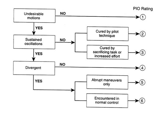
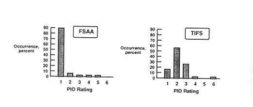
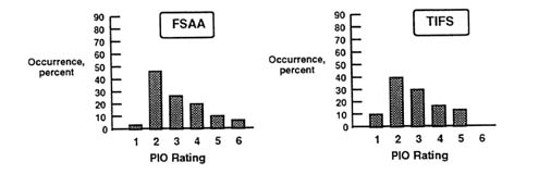
Figure 5-4 A comparison of PIO ratings for formation-flying by the NASA Flight Simulator for Advanced Aircraft (FSAA) and the U.S. Air Force Total In-Flight Simulator (TIFS).
Source: Powers.59
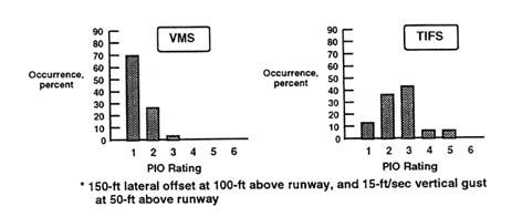
Figure 5-5 A comparison of PIO ratings for demanding landing tasks by the NASA vertical motion simulator (VMS) and the U.S. Air Force total in-flight simulator (TIFS). Source: Powers, 1984.59
A number of approaches were flown to the Niagara Falls airport in which the pilot initially aligned the aircraft to land in a ditch parallel to, but 300 feet offset from, the runway. During the approach, at an altitude of about 150 feet above the runway, the instructor pilot called for the flying pilot to maneuver the aircraft to land on the runway within a predetermined normal touchdown zone. This required aggressive manipulation of the controls, but the task was easily accomplished as long as the aircraft FCS was in its normal configuration.
When the FCS was modified to simulate less-responsive surface actuators, the aircraft flew in a normal manner until the high-gain task was called for. At that point, the aggressive action of the pilot rate-saturated the FCS, which resulted in an APC very close to the ground. The APC was terminated by the instructor pilot executing a missed approach. This change in aircraft behavior was described by the instructor pilot as a flying-qualities cliff. On a subsequent approach with the same FCS configuration, the pilot modified
his actions to avoid the flying qualities cliff, demonstrating the possibility of avoiding an APC problem once the potential for the problem is known.
Demonstrations like this are necessary to train test pilots to determine the APC potential of aircraft and to inform line pilots that APC events may be associated with FCS deficiencies rather than with poor piloting. It is extremely important that line pilots understand that flight characteristics of APC-prone aircraft can change and that they must modify their gains to accommodate the FCS. Pilots should understand that different pilots can have different gains at different times, and it may be possible for one pilot to control an aircraft in circumstances that could lead to an accident with another pilot.
If an aircraft has an APC tendency, sooner or later someone will encounter a problem. Pilots naturally hesitate to admit they have problems flying an aircraft that other pilots have flown without difficulty. With an APC-prone aircraft, the superior test pilot is the one who can detect a problem. A line pilot who discovers an APC characteristic may prevent a tragedy by sharing that information. Thus, it is important to educate both test pilots and line pilots about APCs and to encourage them to report suspected APC events.
Hot-Bench And Iron-Bird Simulation
Hot-bench simulations use actual flight hardware (flight computers, actuators, control surfaces, etc.), rather than simulations that employ mathematical models of these components. If the components just described are located in a frame that replicates their locations on the real aircraft, and if the actuators are subject to simulated aerodynamic loads, the name iron bird is applied to the simulation. Hot-bench and iron-bird simulations are used to verify hardware performance. Their utility in the assessment of a vehicle's susceptibility to APC problems includes verification that the performance requirements and specifications of various flight control subsystems have been met before flight and ensuring that control model switching (e.g., from a primary FBW FCS to a backup mechanical FCS) produces no unwanted transients that could serve as APC triggers. Hot-bench and iron-bird simulations can also be part of pilot-in-the-loop, fixed-base simulation studies that serve as fundamental tools for validating detailed FCS properties, especially in nonlinear regimes. Hot-bench and iron-bird simulations may also be "vehicles" used to develop key describing functions to support some FCS and PVS analyses.
Simulation Summary
The subject of pilot-in-the-loop simulation cannot be left without pointing out the small but finite probability that ground simulators (especially moving-base
simulators) might produce APC events attributable to the limitations of the simulator rather than to deficiencies in the aircraft being simulated. These are often referred to as artifacts of the simulation process. Foremost among simulator limitations are the computational time delays that accrue in generating digital scenes and the necessity of using washout filters and attenuating motion amplitude in the system that provides the simulator cab motion.
The deleterious effects of time delays in actual FCSs and their role in APC susceptibility are well known. Indeed, these delays contribute significantly to the frequency-dependent phase lags described in Chapter 2. Motion washout filters remove the low frequency (large amplitude) components of commanded cab motion, and attenuating motion amplitude further reduces the amplitude of cab motion at all frequencies. But the motion cues the simulation pilot receives are obviously distorted, compared to cues received by a pilot flying the actual vehicle. This distortion can modify pilot behavior in the simulator. It should also be noted that questions about simulator fidelity are sometimes used to explain away anomalies in simulator test results, even when the anomalies are, in fact, characteristic of the system being tested.
Piloted simulations, including fixed-base simulations, have a rich but checkered history as predictors of PIO potential. It is generally recognized that CH PRs (Cooper-Harper pilot ratings) and PIO ratings derived from simulator testing tend to be less discriminating than in-flight ratings, although the trends among comparative configurations may be similar. Ongoing attempts to use simulators to duplicate the severe PIOs from flight tests have shown the following:5
- Simulator tests duplicated some—but not all—of the PIOs demonstrated in flight. However, in all cases aircraft configurations that demonstrated severe PIO characteristics in flight exhibited PIO tendencies in the simulations for all pilots.
- CH PRs and PIO ratings obtained in the simulators indicated somewhat better aircraft performance than flight tests.
- Simulators indicated major differences in workloads and ease of control between configurations that were demonstrated to be PIO-prone and baseline configurations that were free of PIOs.
In short, simulator test results include many key features necessary to assess PIO potential accurately, but the cues and clues are more subtle and less distinct than they are in flight tests.
Overview Of Human Pilot Characteristics
Modern Piloting Tasks
Modern flight control and navigation systems are characterized by two features: (1) they employ FBW controls, and (2) they introduce extensive automation support into the cockpit, ranging from complex SASs in manual control modes to powerful flight management computers* and autopilots that assume responsibility for most flight control tasks (and which may operate the aircraft in ways that are difficult for pilots to monitor and understand). These modern systems leave the pilot in a supervisory control mode most of the time. Consequently, crew members monitor, supervise, plan, and, in essence, serve as information managers. Although pilots have experience flying their aircraft manually, they are seldom in active, direct control of the aircraft. However, if a failure or unexpected upset occurs, they are required to assume control immediately. To maintain situational awareness, pilots must be vigilant, continually aware of the state and characteristics of aircraft systems and continually anticipating situations that could compromise the safe operation of the aircraft; good pilots must "keep ahead of their aircraft."
Human Pilot Performance
Pilot performance can be thought of in terms of three steps: perception, decision making, and action. The pilot's perception involves sensing and interpreting available information. Decision making means the pilot determines what to do next and what control strategy to adopt on the basis of perceptions. Finally, the pilot takes action consistent with the perceived or expected world. Modeling human pilot performance has been a goal of engineers and psychologists for more than half a century. This effort has been most successful in modeling pilot performance in continuous flight-control activity. This is precisely the type of activity associated with PIOs, but not necessarily with non-oscillatory APC events.
Pilot action requires that the pilot act as an element in a feedback control system. Figure 5-6 is a stylized representation of this feedback structure, referred to here and elsewhere as the PVS (pilot-vehicle system). In Figure 5-6, the pilot is shown moving a cockpit control stick or inceptor in response to a visually perceived deviation in aircraft pitch attitude from some desired value. The motion of the cockpit inceptor is an input to the flight control computer. On the basis of information about vehicle motion, the computer then determines an appropriate command to apply to the actuator that drives the appropriate control surface, in this case, the elevator. Figure 5-6 is referred to as a feedback system because, when the pilot visually senses aircraft pitch-attitude
deviations and responds accordingly, he effectively closes a feedback control loop.
The flight control computer may receive signals from vehicle motion as well as commands generated by the pilot. For example, the flight control computer may form part of a SAS, which eases the pilot's burden or workload in piloting the aircraft. As discussed in Chapter 1 (see Figure 1-2), the combination of SAS and aircraft defines the effective aircraft dynamics, and the characteristics of the effective aircraft help determine susceptibility to APC events.
Although visually sensed aircraft motion is probably the most important feedback mechanism for the pilot from the standpoint of aircraft control, a variety of other feedback variables or cues can be sensed by the pilot. These include motion or vestibular cues that provide information about angular, normal, and lateral velocities and accelerations and proprioceptive cues that provide information about the position of the pilot's own limbs when moving the cockpit inceptor. The human sensors that provide both vestibular and proprioceptive cues inherent in human physiology will not be discussed in detail here. Their effects, however, are implicitly included in pilot models for aircraft control.
Discussions of modeling human behavior invariably give rise to questions concerning human variability, adaptability, and choice. Some of the factors that contribute to pilot variability on a global scale may have a cultural basis. For example, pilots from one culture might tend to quickly disconnect an automated system (such as the autopilot or autothrottle) if they do not understand what it is doing, whereas pilots of another might persist in the belief that automated controls outperform manual control.
The pilot-modeling efforts of direct interest to PIO applications are focused upon very well defined piloting tasks in which human behavior is, by necessity, highly constrained. For example, a well trained, well motivated pilot
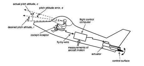
Figure 5-6 A feedback system involving the human pilot.
engaged in landing a large commercial aircraft is constrained by the task and environment to the extent that the pilot's behavior and performance can often be adequately described by what is referred to as a "describing function model."34,44 In its complete incarnation, such a model describes both the pilot's "linear behavior" (i.e., behavior that could be replicated by a relatively simple inanimate control device with linear characteristics), and the pilot's "nonlinear behavior" (i.e., behavior that can be attributed to the complex, nonlinear sensing and actuation capabilities of a human being).
Pilot Models And Pilot-Vehicle Analyses
Mathematical models of human pilots have been developed along the lines of control theory. Indeed, the control theory paradigm has become the primary way engineers view the human pilot in well defined piloting tasks. It is not surprising, then, that synthesizing models of the human pilot closely parallels synthesizing inanimate controllers in feedback control systems. Just as control-system design techniques can be conveniently partitioned into classical and modern approaches, so can techniques for modeling the pilot. In addition to the classical-modern dichotomy, one can also distinguish pilot models on the basis of their ability to model the physiological subsystems responsible for sensing and actuation (e.g., the sensors of the inner ear that provide human beings with information about self-motion and the neuromuscular combinations that allow precise movement of the limbs).
Classical Approach
Background
Classical control-system design techniques employ frequency-domain synthesis. In simple terms, these techniques transform the variable that describes duration (i.e., time) into one that describes the rapidity of change (i.e., frequency). Because time is such a natural measure, this transformation would seem to obscure the problem. However, the advantages of the frequency domain approach have been known to control system engineers since the 1940s.6
In the classical approach, the human pilot is represented by what is referred to as a describing or transfer function.34,44 The transfer function is a frequency-domain representation that can predict a system's output (in the time or frequency domain) as a function of its input. Figure 5-7 is a block diagram of this cause-effect representation. (This kind of representation was also used in Figure 1-2 in a much more detailed form.) The lines with arrows represent physical, time-varying signals. The directions of the arrows represent cause and effect; the line directed toward the block represents a "cause," or input,
and the line directed away from the block represents an "effect," or output. The block itself represents the transfer function of the system in question (e.g., the human pilot).
As an example, referring to Figure 5-6, the input to the pilot could be the time-varying signal that is the difference between the desired and actual aircraft pitch attitude; the output from the pilot could be the time-varying signal that is the cockpit inceptor motion. The use of the word "signal" for the variable in question can be traced to classical control-system design, which began with the work of electrical engineers.6
Crossover Model
One of the simplest, but perhaps most profound, models of the human pilot is called the "crossover model." The name derives from the particular frequency range (i.e., the crossover region) in the frequency response diagram of the transfer function for the combined system of the pilot and the controlled element where the model is most accurate. The crossover model effectively describes how a human pilot can adapt to the response characteristics of various aircraft. This model is an archetype of appropriate feedback control operations in that it follows the most fundamental rule of thumb for synthesizing inanimate control systems: the characteristics of the control system are adjusted so that the cause-effect relationship between system error and system output approximates integration in the time domain.
Consider Figure 5-8, where a second block has been added to the diagram in Figure 5-7. The second block represents the characteristics of the aircraft. The crossover model states that the transfer function obtained by a combination (multiplication) of the transfer functions of the pilot and the vehicle in Figure 5-8 will have a very simple form in a limited but important frequency range (called the crossover region). This form, which describes time integration (with a time delay) of the visually-sensed input error, is equivalent to a dynamic system element that includes a time delay (including human reaction time) and produces an output that is the time integral of the delayed input. This model has been applied several times elsewhere in this report.
A number of pilot model formulations can be traced to the crossover model. Some of these reflect feedback associated with detailed neuromuscular physiology. No descriptions of these models will be attempted here. Specific examples of relevant models for high-frequency PIOs can be found in other studies.33,37
Synchronous Pilot Model
An examination of the time histories associated with many PIOs indicates that, during a PIO, the cockpit inceptor motion is nearly in phase with, or
synchronous with, the vehicle oscillation. This suggests that, in analyzing the PIO, the pilot model can be reduced to a simple gain, with a magnitude that produces incipient instability from the standpoint of control system design. The quotation from Gibson given earlier reflects this form of pilot behavior. In another recent study,42 the utility of this approach was shown using data from a well documented series of flight tests.5 The obvious advantage of this approach is that it dramatically simplifies the pilot modeling procedure while simultaneously focusing attention upon the shortcomings of the dynamics of the effective vehicle, which are the underlying causes of the APC. The synchronous pilot model is, without doubt, the most valuable pilot model for providing insight and understanding of fully-developed PIOs. It is also by far the simplest. The synchronous model is also applied elsewhere in this report.
Modern Approach
Background
The advent of powerful computer algorithms to design control systems has led to the development of algorithmic pilot models, which are generated by sophisticated computer-aided-design programs for control-system synthesis. Although the modern approach emphasizes system description in the time domain as opposed to the frequency domain, models in this category can be compared with the classical ones by a simple transformation from one domain to the other.
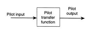
Figure 5-7 A block diagram representation of the human pilot transfer function.
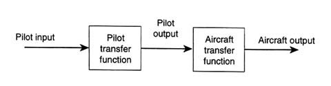
Figure 5-8 A block diagram of an open-loop PVS.
Optimal Control Model
One successful example of pilot modeling using the modern approach is the optimal control model (OCM) of the human pilot.34 The primary hypothesis behind the OCM is that the trained, motivated human pilot behaves in an optimal manner. Thus, in a well defined flight task, the pilot attempts to optimize an inferred performance measure, typically represented by a weighted sum of average control error and average inceptor rate. The latter quantity is often taken as a measure of pilot workload. The optimization of the performance function by means of mathematical algorithms derived from linear optimal control and estimation theory leads to a specific form for the model. (In the parlance of the classical approach, this model would be referred to as a specific transfer function.)
The OCM of the human pilot is well suited to modeling pilot behavior in well controlled experimental conditions, such as those occurring in ground or in-flight simulators. The model is ideally suited to handling multiple pilot cues (e.g., vestibular as well as visual cues) and to modeling pilot activity in which more than one vehicle response is being controlled by the pilot (e.g., controlling aircraft roll attitude as well as pitch attitude). Useful examples of applications of the OCM to pilot modeling can be found in the Handbook of Human Factors and Ergonomics.34 Unfortunately, because the OCM is based on optimal pilot behavior, it does not reproduce the incipient instability that accompanies APC events. It can, however, be used to estimate pre-transition and long-term post-transition pilot dynamics for Category III PIOs. Pilot rating predictions can also be made from OCM results. Such estimates can show workload changes implicit in the pilot's adaptation to changes in the effective aircraft dynamics. These changes can indicate the difficulties of possible transitions that are candidates for Category III PIO triggers.
Finally, the OCM or a variant can be useful in estimating pilot lead or lag time, which can be used in the Moscow Aviation Institute boundaries (described in Chapter 6).
Different Modes of Pilot Behavior
Compensatory Control
It should be emphasized that, except for the synchronous pilot model, the type of pilot behavior that has been discussed to this point is usually referred to as ''compensatory." That is, the pilot senses a discrepancy between a desired state and an actual aircraft state (e.g., pitch attitude), and the pilot compensates for the errors by providing a corrective input. Consider Figure 5-9, which describes a complete feedback system. To explain the diagram in more concrete fashion, assume that the input (i) is a time-varying aircraft pitch-attitude
command generated by the flight control computer and displayed electronically to the pilot in the cockpit. The pilot's task is to force the aircraft to follow this command with minimum error. However, in the example, the cockpit display only indicates the system error (e) to the pilot. The situation shown in Figure 5-9 defines the compensatory piloting task in which the pilot's actions respond to system error. Another example of compensatory behavior occurs when a pilot is using the instrument landing system display in the cockpit to conduct a landing. This display provides information regarding aircraft position above or below the desired glide slope.
The exquisite adaptability of the human pilot allows other types of behavior, most of which have been studied and categorized extensively.44 These are briefly described below.
Pursuit Control
Assume that a display modification in Figure 5-9 is undertaken so that the system input (i) and aircraft output (c) are displayed in the cockpit, the latter being the actual aircraft pitch attitude. Because both i and c are now available, the difference (e) could also easily be visually extracted by the pilot. If the pilot makes use of this added display information, "pursuit pilot behavior" would be in evidence. The word "pursuit" is used because the pilot's control action can be thought of as being generated by his pursuit of the command signal. That is, the pilot pursues the goal of matching c to i, thereby minimizing e. Under many circumstances, the pilot can actually sense the quantities needed for control and can "develop" his or her own internal pursuit display.
Precognitive Control
There is evidence of another model of pilot behavior that may not involve continuous feedback at all. Once the pilot has become completely familiar with the aircraft response characteristics and the perceptual field, a highly-skilled pilot can, under certain conditions, generate deft, discrete, properly timed, and
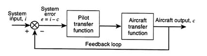
Figure 5-9 A block diagram of a closed-loop PVS.
sequenced outputs (i.e., movements of the cockpit inceptor) that result in aircraft responses that are almost exactly the ones desired. This mode of behavior has been referred to as "precognitive" control. Most highly skilled movements that have been thoroughly learned and practiced enough to become automatic (i.e., not requiring conscious thought) fall into this category. Synchronous behavior for sinusoidal inputs is, perhaps, the most common example and is certainly the most important for PIO considerations.
Organization of Perceptions
Given appropriate visual cues, the human pilot is capable of organizing his or her own perceptions (in essence, creating internal pathways) to adopt any one of the behavior modes described above. Indeed, a theory referred to as the successive organization of perceptions theory has been forwarded to describe this type of skill development.44 There appear to be distinct advantages to the pursuit and precognitive control models in terms of improved pilot-vehicle performance and reduced pilot workload.
Remarks
The modes of possible pilot behavior outlined above would certainly appear to complicate the issue of pilot-vehicle analysis. Each of the three pilot-modeling approaches (crossover, synchronous, and OCM) is capable of describing at least the compensatory and pursuit behavior modes.44 Pilots may trigger APC events by switching from one mode to another (e.g., from pursuit to compensatory control) if the underlying conditions for an APC event are present.
Applying Pilot Models to the APC Problem
If the crossover, synchronous, and OCM pilot models are indeed descriptive of human pilot behavior, the question naturally arises as to whether they can successfully describe conditions that lead to or catalyze PIO problems. Generally speaking, the answer to this question is "yes" for fully developed PIOs. A study by McRuer includes historical background to the successes that have been achieved in this area.42 Unfortunately, existing pilot models are not suitable for describing the transients of APC phenomena, including the developmental details of non-oscillatory APCs and the initial transient pilot changes involved in Category III PIOs.


