
2
Varieties of Aircraft-Pilot Coupling Experience
Introduction
From the pilot's perspective, aircraft-pilot interactions fall somewhere between two extremes—the pilot may be fully interactive, or the pilot may be effectively detached. In the fully interactive extreme, the pilot is said to be "in the loop," and the PVS operates as a closed-loop feedback control system. In this situation, the pilot's commands are more or less continuous and depend, at least partly, upon pilot-perceived "errors" or differences between desired and actual aircraft responses. Near the opposite extreme is the "open-loop" control system, in which the pilot operates as a forcing function, generating commands to the effective aircraft that are not directly related to the pilot's perception of aircraft motion. In either case, the PVS operations involve "aircraft-pilot interactions" that constitute an all-inclusive set.
The interactions may result in motions that are desirable and "benign" or "undesirable." For this study, the interactions of interest are primarily closed-loop in character. They can result in favorable PVS responses that converge to provide the desired PVS performance, or they can result in undesired responses, either oscillatory or divergent. The focus here is on unfavorable, closed-loop PVS responses, both oscillatory and divergent. Unfavorable responses need to be understood in the context of the all-inclusive set of all PVS operations. The hierarchical structure shown in Figure 2-1 provides a taxonomy that is useful for classifying, discussing, and analyzing APC phenomena.
At the highest level, aircraft-pilot interactions are divided into benign and undesirable. Routine piloting, which is the most prevalent form of aircraft-pilot interaction and which can involve both open-loop and closed-loop operations of the PVS, is shown on the far left of Figure 2-1 as the most benign (and desirable) class. Routine piloting includes all well-accomplished piloting tasks as well as two kinds of PVS oscillations. The first, which arises from incomplete pilot adaptation to the effective aircraft dynamics, is very common and, fortunately, usually benign. These oscillations usually occur when the pilot is adapting to the aircraft dynamics and performing high-gain, precision-control tasks. For example, 15 oscillation incidents occurred during testing of the SAAB J-35 in 1960; 7 of these occurred when a pilot was flying the J-35 for the first time.
From time to time in this learning process, the pilot's gain is momentarily high enough to create a closed-loop oscillation. The usual initial "cure" is simply for the pilot to get out of the loop by releasing the inceptor and relying on the stability of the effective aircraft dynamics to handle the recovery. Because this is basically a learning experience, the ultimate cure is practice.
The other kind of closed-loop PVS oscillations that can be considered normal is a low-amplitude, damped oscillation, which is often referred to as a "bobble." Bobbles are associated with short-duration, excessive pilot gain. They are, at worst, short-term, mild PIOs that do not cause difficulties in controlling the aircraft.
The next class of favorable and benign interactions includes oscillations deliberately introduced by the pilot to generate a periodic forcing function. The outstanding example of this is "stick pumping," when the pilot applies an oscillatory input to the aircraft either to "feel out" its effective dynamics or to counter large control-system nonlinearities (as a kind of "dithering control"). The pilot's input constitutes an open-loop forcing function, and the pilot's action and the resultant aircraft oscillation frequency are not directly conditioned by the aircraft's response.
The undesirable APC events that are the subject of this study appear in the right half of Figure 2-1. Within this group, PIOs are distinguished from non-oscillatory APC events like divergences. The oscillations are akin to the benign "learning experience" variety, but they are not associated with pilot maladaptation. In fact, the pilot may be very experienced with the aircraft and with the task in general. Sometimes, however, the task specifics suddenly become unusually severe, requiring a highly aggressive pilot response to exert precise control and regulation of the aircraft. In this situation, getting out of the closed loop is not always feasible, so the demands for recovery focus on the PVS rather than just on the effective aircraft. Forced by circumstances to retain some level of control while attempting to recover, the pilot's gain may be too high but cannot be relaxed. The result can be a severe or even catastrophic PIO even with the very best, most well adapted pilot. The pilot-vehicle closed-loop system is simply not up to the demands imposed on it.
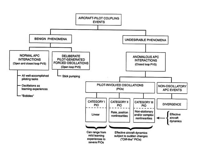
Depending on the effective aircraft dynamics, three categories of unfavorable PIOs can be distinguished. (Each of these categories is described in more detail in the following section.) For Category I PIOs, the dynamics are essentially linear; Category II and III PIOs involve nonlinearities in the effective aircraft dynamics. In Category II PIOs, the nonlinearities result from rate or position limits (the rest of the effective aircraft dynamics are essentially linear). The nonlinear features in Category III PIOs are more complex. The nonlinear properties in both Category II and III PIOs can cause sudden changes in the effective aircraft dynamics that result in the abrupt (sometimes referred to as "cliff-like") onset of PIOs.
The class in Figure 2-1 furthest to the right comprises non-oscillatory APC events. These Category III events can stem from several causes and tend to be highly idiosyncratic. Only a very few incidents have been identified to date, but the advent of FBW technology has introduced some new dimensions by permitting control mechanizations that can be troublesome, especially in highly limiting conditions.
The next section, Categories of Aircraft-Pilot Coupling Oscillations, begins with a description of the three categories of oscillatory APCs. This description is followed by discussions of nonlinear, "cliff-like" PIOs and of non-oscillatory APC events. The next major section, Triggers, presents a fuller description of the underlying conditions and the kinds of triggers thought to be involved in initiating adverse APC events of all classes. Finally, several varieties of PIOs are illustrated by case studies. Four detailed examples are presented, along with a separate discussion of APC issues related to rotorcraft. The case studies are typical incidents and accidents encountered in the development phases of recent FBW systems. They are particularly instructive in that each exhibits a PIO in a concrete and specific context. Taken together, they provide a broad picture of a variety of potential triggers, patterns of behavior, PIO frequencies, and so on.
Categories Of Oscillatory Aircraft-Pilot Coupling Events
Because of the diversity in control axes, frequency ranges, and other important characteristics of PIOs, several kinds of classification schemes could be used. In the discussion of historical antecedents in Chapter 1, some notable PIOs were grouped by primary control axis and PIO frequency. Analytical studies such as McRuer42 rely on pilot behavioral models and closed-loop analysis procedures. These studies are used to elicit understanding and explain the phenomena and their associations as well as to develop and assess system modifications to reduce the potential for PIOs. The pilot models and analysis procedures are not specific to any one group in Tables 1-1a through 1-1d. This suggests that a desirable classification scheme should accommodate existing
pilot behavior models, be consistent with procedures for analyzing appropriate feedback control systems, and have direct connections with the varieties of PIO as these are reflected in experimental databases for pilot and PVS dynamics, PIO experiments, etc. To fulfill these objectives, the categories described below have been adopted. The three categories organize PIOs into classes according to whether they are essentially linear, characterized by one or two common nonlinearities, or characterized by more complex and extensive nonlinear features.
Category I: Linear Pilot-Vehicle System Oscillations
In Category I PIO phenomena, the effective aircraft characteristics are essentially linear, and the pilot behavior is "quasi-linear" and "time-stationary." Quasi-linearity means that many nonlinear elements have specific input-response pairs that appear to be similar to the input-response pairs for linear systems. This similarity leads to the notion that the pilot's output response to certain inputs can be divided into two parts: (1) the response of a linear element (known as a "describing function") that is driven by the particular input; and (2) an additional quantity (called the "remnant") that is added to this response. In the PIO situation, the input is sinusoidal (or nearly so), and the pilot's output is a periodic function that constitutes the sum of (1) a sinusoid at the same frequency and (2) a remnant composed of higher harmonics. These harmonics will ordinarily be significantly attenuated as they proceed around the PVS loop, so they do not usually materially affect the input to the pilot. The causally significant part of the pilot's dynamics in the PIO is then the pilot's sinusoidal input describing function, which for a particular input amplitude acts like a linear transfer characteristic. The time-stationary aspect of the Category I PIO means simply that the effective aircraft dynamics and the pilot's dynamics do not change during the PIO.
In Category I PIOs, no significant frequency-variant nonlinearities28 operate in the controlled element dynamics. Simple amplitude-dependent series gain changes either in the pilot gain or the controlled-element gain can be considered special cases, so such things as nonlinear stick sensitivity or shifts in pilot attention may be admissible as features consistent with a Category I event. PIOs in this category may be deliberately induced by the pilot increasing his gain, in which case the situation is easily repeatable, readily eliminated by relaxing control (lowering pilot gain), and generally not threatening. In other circumstances (for example, when there are tight flight-path constraints and major triggering events or disturbances), the pilot may not have the option of reducing gain. Those cases may produce severe Category I PIOs.
For a given pilot cue structure, analyses of Category I PIOs can reveal pilot-vehicle, closed-loop system dynamics, bandwidths,* resonance properties, etc., for nominal and PIO-based pilot gain levels, estimated pilot
ratings and commentaries, and the sensitivity of closed-loop system properties to changes in the effective aircraft characteristics. The easiest feature to estimate for Category I events is the frequency range, which depends primarily on the pilot's behavior pattern (compensatory or synchronous) and the degree to which the higher-frequency dynamics of the pilot's neuromuscular system* may be involved. (Behavior patterns are well known in human-machine systems studies.42,45) A cross section of frequencies that have been observed appears in Table 2-1. In some PIOs, the pilot's behavior may initially be compensatory but may change to synchronous as the oscillation develops.
The two key effective-aircraft factors associated with susceptibility to an essentially linear PIO are those that unduly restrict the pilot's ability to close the PVS loop for a broad range of gains or to achieve adequate closed-loop system performance. Much of the existing data on PIOs and poor flying qualities could be used to exemplify these factors and define them more quantitatively. Some aircraft configurations and associated analytical studies are particularly well suited to detailing these factors5,42 Such analyses can provide a more quantitative understanding of the effects of various effective-aircraft dynamics. Appendix C compares PVS dynamic properties for two configurations with almost identical effective aircraft dynamics except for high-frequency phase lags.* Excessive phase (or time) lag is one of the two most important aircraft-associated factors in Category I PIOs because it limits both the possible range of pilot gain adjustments and the attainable crossover frequency. These limitations directly affect the closed-loop PVS bandwidth and performance. The criteria for Category I PIOs, which are examined in detail in Chapter 6, give a quantitative answer to the question of just how much lag is "excessive."
TABLE 2-1 Cross Section of Frequencies
|
PVS Characteristic |
Typical PIO Frequencies |
|
Compensatory (pilot closes PVS loop to minimize error) |
|
|
Extended rigid body effective aircraft and low-frequency pilot-neuromuscular system |
2 to 5 rad/sec (0.3 to 0.8 Hz) |
|
Extended rigid body effective aircraft and high-frequency pilot-neuromuscular system |
10 to 20 rad/sec (1.5 to 3 Hz); (sometimes referred to as "ratchet") |
|
Synchronous (pure gain pilot dynamics) |
|
|
Extended rigid body effective aircraft and low-frequency pilot-neuromuscular system |
4 to 10 rad/sec (0.6 to 1.5 Hz) |
|
Flexible mode effective aircraft and high-frequency pilot-neuromuscular system |
6 to 20 rad/sec (1.0 to 3.0 Hz) |
|
Source: McRuer.42 |
|
The other major factor in Category I PIOs is inappropriate effective aircraft gain. This can be either too high (aircraft is too sensitive to control) or too low (aircraft is too sluggish). Too-high aircraft gain is a more important factor in Category I PIOs.
Finally, it is important to reiterate that essentially linear (Category I) PIOs are not always severe. Linear PIOs are likely to occur whenever the pilot's dynamic adaptation is faulty. These PIOs can be commonplace learning experiences that disappear as the pilot becomes familiar with the aircraft's characteristics. However, linear PIOs that occur because of excessive time lag, inadequate available gain range, or both, do not disappear and can often be severe. They are likely to be encountered whenever the PVS is confronted with extreme demands, either for high-precision control or for control of large upsets or other unexpected events. Excessive time lag and inadequate available gain range are design flaws that should be eliminated as a matter of flight safety.
Category II: Quasi-Linear Pilot-Vehicle System Oscillations with Rate or Position Limiting
Category II PIOs are severe oscillations with amplitudes well into the range where rate and/or position limits become dominant. Rate limiting goes beyond the Category I scenario by adding an amplitude-dependent phase shift and by setting the amplitude of the limit cycle.* Category II events appear to be the most common jump-resonant, limit-cycle, oscillatory APC events. (An example of jump-resonance appears below in the section on Rate Limits.)
The characteristics of typical Category II PIOs are described in the discussion of rate limiting in the next section and in more detail in Appendix C. These events are classified as a separate category primarily because rate limiting is present in a large proportion of severe PIOs. Rate limiting can be analyzed readily, and it is, perhaps, the most easily identifiable cause of a flying qualities cliff. Category II is a transitional category between Category I PIOs and the most general, nonlinear Category III PIOs.
Category III: Nonlinear Pilot-Vehicle System Oscillations with Transitions
Category III PIOs depend fundamentally on nonlinear transitions in either the controlled element or the pilot's behavioral dynamics. Shifts in the controlled element can be associated with the magnitude of the pilot's commands (akin to the rate limiting onset property in Category II). Category III PIOs may also result from a change of mode, from other internal changes
in the FCS, or from changes in the aerodynamic or propulsion configuration of the aircraft.
Category III PIOs can be much more complicated than Category I or II PIOs because they necessarily involve transitions in the dynamics of either the pilot or the effective aircraft. Thus, a minimum of two sets of effective PVS characteristics are involved in Category III PIOs—pre-transition characteristics and post-transition characteristics. If these differ greatly, as they did in the T-38 and YF-12 incidents, very severe PIOs can occur.
Nonlinear, Cliff-Like, Pilot-Involved Oscillations
For years, the test pilot community has recited a litany of anecdotal observations such as the following:
- Severe PIOs are sudden and unexpected.
- Sometimes, just moments before the explosive onset of a severe PIO, the aircraft is docile and easily controlled.
- Flying qualities cliffs are "out there" awaiting the right circumstances to appear and create havoc.
The validity of these observations is demonstrated by the historical events described in Chapter 1 and the case studies at the end of this chapter. The "cliff" metaphor is used to convey a sense of unexpected, dramatic, and excessively large motions of the aircraft. When cliff-like changes result from an incremental increase in the amplitude of the pilot's output, the PVS is not behaving like a linear system. Instead, this indicates the presence of significant nonlinearities either in the dynamics of the effective aircraft or in the pilot's behavior. The resulting PIOs are severe and exhibit rate-limited responses or other limit-based response patterns. Many, if not all, Category II and III PIOs exhibit cliff-like behavior.
An interesting and instructive example of cliff-like APC events was encountered during flight tests of an F-14 backup flight control module with significantly restricted rate limits.
Of particular interest to fleet operators was the feasibility of inflight refueling and shipboard landing. Given the decrease in available stabilator rate from 35 to 10 degrees per second, the test team recognized the potential for APC due to rate limiting. An incremental build-up was designed,…progressively sampling the flying qualities at decreasing ranges from the tanker aircraft, and culminating in basket engagement. Throughout the approach to approximately 5 feet from the basket, the team was delighted to observe solid Level I handling qualities. They then confidently
proceeded to engagement. Immediately upon probe contact, a longitudinal APC event initiated. Though the pilot immediately selected idle power and extended the speedbrakes, the ensuing departure was so violent that his aircraft was above the top of the vertical tail of the tanker and in 90-degree angle-of-bank prior to the probe separating from the basket. The photo/safety chase [aircraft] 500 feet abeam had to aggressively maneuver to preclude being struck by the test aircraft, and the refueling store was badly wrenched from its position on the tanker's wing pylon. The test team's naive reliance on incrementalism had badly failed them.55
The results of a later flight test during which a similar APC event occurred gave more detailed information about the sudden shift in PVS behavior, including why the buildup did not reveal the severe handling qualities cliff.
Obvious from this second departure was a significant stab for the center of the basket after the probe had passed the lip of the basket. …the instrumentation revealed a three-fold increase in the magnitude of the pilot's longitudinal inputs in the seconds immediately prior to basket contact. In retrospect, this was attributed to a tanking technique in which the pilot flew formation off of the tanker fuselage up to within 2–3 feet of the basket. At that point, the pilot's point of reference shifted to the basket itself as he maneuvered the aircraft to seat the probe directly in the basket coupling. …In shifting the reference to the basket the control [precision demanded] abruptly tightened to inches [from feet], with a consequent abrupt increase in gain over that which had been required to maintain even very tight formation.55
These incidents reveal several features of cliff-like phenomena—sudden changes in the "architecture" of the closed-loop PVS as "constructed" or set up by the pilot and dramatic changes in the effective aircraft dynamics in response to changes in the pilot's commands. The consequence is the sudden onset of highly dangerous, closed-loop system behavior. The flight test doctrine of "incrementalism," in which potentially dangerous conditions are approached carefully and gradually can be a "cruel deceiver in obscuring PIO perils" in situations where the sudden onset of a highly nonlinear gain or phase lag can trigger an APC event.55 It is essential that reliable test procedures be developed for discovering and exploring the nature of sudden shifts in the PVS that may contribute to severe APCs.
Common Cliff Producers
The cliff metaphor evokes a picture of sudden, large changes in aircraft motions associated with relatively slight changes in pilot activity. Such changes can only occur if there are significant nonlinearities in the PVS dynamics.
In conventional manual control systems, the most common nonlinearities are rate and position limits in surface actuators and various design features (such as preloads, thresholds, and detents) of cockpit manipulators (inceptors) that are designed to offset unavoidable frictional and other unfavorable effects. APC problems that can arise from these characteristics are well known among the cognoscenti, and major attention is invariably paid to them in design and flight testing.
The actuator rate and position limits are central matters in design; conditions under which rate limiting is likely to be encountered, as well as pilot techniques for coping with it, are well understood. On some older aircraft, rate limiting in surface actuation occurs when mechanical stops in hydraulic control valves (e.g., servo valve bottoming) limit continued movement of cockpit manipulators so the pilot may have a direct cue that rate limiting is present. Such features are not present on more modern, mechanically signaled aircraft, where valve over-travel is provided, and the cockpit crew is not aware when actuators are operating at the rate limit. In FBW designs, the crew has no physical connection at all to the actuators, so surface actuator rate limits are not directly apparent to the pilot. However, it is possible to design FBW systems that synthesize direct-control feel to the pilot, including inceptor motions that reflect automatic system commands or even the current position of the control surfaces.
In contrast to classical aircraft, FBW FCSs offer a broad range of possibilities for nonlinearities that can be easily implemented. The greater variety of system mode possibilities requires a fairly large number of nonlinear elements just to cope with shifts in FCS mode and aircraft configuration with changes in various interfaces, etc. The easy-to-mechanize aspects of digital control also provide a fertile field for the introduction of special situation-sensitive features intended to offset events that designers perceive as unfavorable. Thus, limiters are deliberately inserted after command signal integrators; and elaborate nonlinear features are used to reduce the undesirable time lags caused by integrators (e.g., integrator windup). Limiters are also used to set relative degrees of command authority for various functions to keep the rate limiting intrinsic in actuators from destabilizing the SAS (stability augmentation system).
In other words, there may be good reasons to introduce nonlinear features into the FCS using FBW technology. Unfortunately, designers do not always have a comprehensive understanding and appreciation of the accompanying side effects, not the least of which can be an enhanced susceptibility to adverse APCs. To illustrate how these nonlinear features can affect PIO potential, two
examples of nonlinear features capable of producing cliff-like behavior in FBW systems are described below.
The two most common and significant nonlinear characteristics within the effective aircraft (see Figure 1-2) that affect closed-loop operations are command-path gain shaping and rate limiting. These are introduced by the FCS rather than the aerodynamics of the aircraft. Figure 2-2 shows a simplified view of these nonlinearities in a FCS-aircraft combination. In this system, rate limiters are present in several different locations.
In the primary manual control systems of yesteryear, the major source of rate limiting was fully powered, surface actuating subsystems. These are still present although they are sometimes ''protected" from becoming active by pre-actuator rate limiters. Because these nonlinear features are present by design, they are adjustable, in principle. Any unintended harm they may do, such as contributing to a severe APC event, should be viewed as a design flaw.
Rate Limiting
Extensive control-surface rate limiting has been observed in most recorded severe oscillatory APC events, but the initiation of these events has often been attributed to other causes, usually excessive time lags. It is assumed that these time lags build up to a rate-limited oscillatory amplitude. This thesis is based on analogies with linear systems. Such excessive lags have been shown to result in poor flying qualities and to be major contributors to PVS oscillations. The excessive time lag thesis can be further supported by flight test demonstrations indicating there is some merit in "alternate control schemes" designed to offset the effects of time lag caused by rate limiting.1,10,41 Detailed analyses also support the notion that rate limiting can exacerbate the effects of time lags.3,14,15,31,39,46
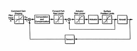
Figure 2-2 Most common FCS locations of command gain shaping, rate limiters, and position limiters.
Although it is clear that rate limiting phenomena are important factors in fully-developed, severe PIOs encountered in operational situations, the actual process by which rate limiting causes severe PIOs is neither well documented nor well understood. The possibility that rate limiting phenomena are primary initiating factors in the development of some severe PIOs has not received enough attention despite compelling evidence. In the F-14 example described above, for example, the sudden appearance of rate limiting features in the FCS contributed to an unexpected cliff-like situation. At its most insidious, rate limiting phenomena can cause the sudden, dramatic onset of a substantial incremental shift in the phase lag, which is instantly manifested by a change in pilot gain or command. This change is equivalent to suddenly increasing the time delay in the loop.
The general effects of rate limiting in a surface actuation system are shown in Figure 2-3. Figure 2-3a is a block diagram of a simplified surface
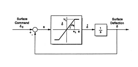
Figure 2-3a Surface actuator rate limiting effects for various input amplitudes in a closed-loop surface actuator system. Source: Klyde.39
eL = value of a corresponding to ![]() = VL
= VL
e = actuator error (i.e., the difference between the feedback signal, δ, which indicates control surface position, and the "goal position," δc, as indicated by the current surface command)
VL = actuator rate limit
ωa = bandwidth of the closed-loop actuator when operating in the linear region 1/s indicates integration
actuation system. Figure 2-3b illustrates that, for small amplitude commands, the actuator follows the command input with a small time lag (defined by the inverse of the bandwidth of the actuator as a linear system). The actuator command input, error, and output are all sinusoidal and show no effects of rate limiting. In Figure 2-3c, the amplitude of the command input is large enough to begin saturating the output velocity, but there is still little apparent effect on the output position. The time lag between input and output is essentially unchanged from the time lag of the linear system. Finally, when the command input is just a bit larger (as shown in Figure 2-3d), the actuator is rate limited (either positively or negatively) for most of the cycle. The output velocity is nearly a rectangular wave, while the output position approaches a triangular wave. Most important, the time lag between the command input and the command output is no longer even remotely related to the linear system bandwidth. Instead, it is a function solely of the rate limit and the input amplitude and frequency.
The increase in input amplitude necessary for the actuator to go from the marginal condition of Figure 2-3c to the condition of Figure 2-3d is relatively small in comparison to the input amplitude range consistent with linear operation. Thus, the onset of a significant change in phase lag can be sudden because it coincides with an increase in pilot command amplitude. From the pilot's perspective, the phase and amplitude characteristics of the actuation system change from a condition of almost no time lag (nearly pure gain) to a condition of major phase lag. In practice, this is sometimes called the "pilot overdriving the actuator," although there may be no indication to the pilot (other than an inconsistency in the aircraft's response) that the actuator is being "overdriven."
In aircraft with older versions of primary manual control systems, the onset of rate limiting may first become evident to the pilot by an increase in stick or control-column forces when the surface actuator servo valve "bottoms" (hits its internal stops). In these aircraft, the "position lag" between the pilot and the control surface seldom exceeds the valve displacement from its neutral position; as measured in degrees of control surface rotation this is typically small, on the order of 2 degrees. Thus, the pilot's output and the surface deflections are seldom far apart, and the time lag illustrated in Figure 2-3d is usually limited. Because of the mechanical connection, the sinusoidal nature of the input from the pilot shown in Figures 2-3a to 2-3d cannot be sustained except within the narrow confines of the ''position lag."
The situation can be very different in more modern, mechanically signaled, primary manual control systems or in FBW FCSs; in these systems, there may be no indication whatsoever of this or other varieties of rate limiting. Therefore, the type of time lag shown in Figure 2-3d can become fully developed without being detected.
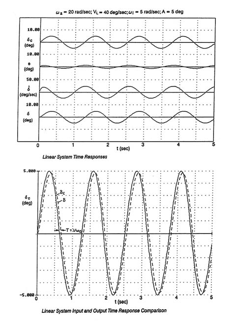
Figure 2-3b Surface actuator rate limiting effects for various input amplitudes showing linear system response times. Source: Klyde.39
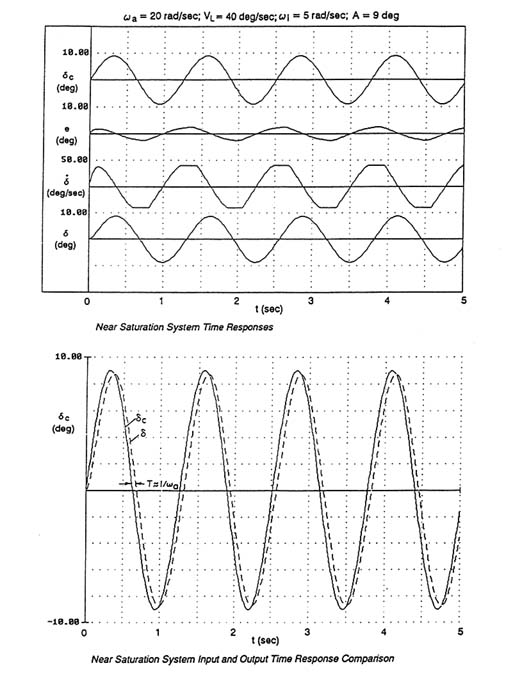
Figure 2-3c Surface actuator rate limiting effects for various input amplitudes showing near saturation response times. Source: Klyde.39
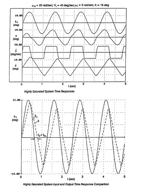
Figure 2-3d Surface actuator rate limiting effects for various input amplitudes showing highly saturated response times. Source: Klyde.39
A typical scenario begins with a pilot who is well adapted to an essentially linear, pilot-aircraft closed-loop system operating at high gain to satisfy task requirements for precision control (akin to the initial phases of the F-14 attempt to line up the refueling probe with the tanker drogue). If the pilot is confronted with task demands that call for a bit more pilot control amplitude or gain (like the pilot's attempt to finally couple with the drogue), slight increases in either pilot amplitude or gain (or both) may be sufficient to enter the nonlinear rate limiting regions, with the concomitant introduction of a sudden phase lag into the closed-loop system. In terms of the underlying physics of closed-loop systems, this is an example of a "jump resonance" phenomenon.28
This description suggests that rate limiting phenomena can be the main source of a flying-qualities cliff. This theory is based on the identification of rate limiting as a feature that can lead to the nonlinear oscillatory jump resonance phenomenon and is supported by studies done independently in Germany and in the United States.3,15,39,46 The jump resonance phenomenon also emphasizes nonlinear concepts consistent with the experience of test pilots.
Jump resonance phenomena are not, of course, confined to rate limiting paradigms. An illustrative example showing rate limiting in more detail can be found in Appendix C. This example is instructive in two respects. First, the onset of rate limiting is indeed sudden and can have an immediate and substantial cliff-like effect. Second, the conditions under which onset can actually occur demand that the PVS be closed at very high gain. The PVS is assumed to be compensatory, described by the simple crossover model, with the rate limiting describing function fully developed. With these assumptions, the linear system before the onset of rate limiting has to be closed with a very high gain, corresponding to phase margins* of less than 20 degrees. When the pilot's amplitude (or gain) is increased to put the system past the onset of rate limiting, the closed-loop system immediately becomes unstable and a limit cycle is established. Similar results assuming synchronous pilot-loop closures have been obtained in another study.17 There, a time domain simulation that demonstrated the jump resonance was used to validate frequency domain assessments that defined the onset conditions.
Because requisite circumstances are unusual, cliff-like phenomena are difficult to generate unless nearly exact conditions are present. In practice, this sensitivity to the conditions at onset parallels the unusual sequence that occurred with the F-14 refueling example cited above. This sensitivity also helps to explain the difficulties encountered when piloted simulations or even flight tests are used as a discovery process. The ability to analyze and pinpoint the precise conditions should make it possible to identify APC possibilities more accurately.
Command Path Gain Shaping
Almost all FBW FCSs incorporate gain shaping in the pilot's command path. Gain shaping adjusts the gain of the effective aircraft dynamics as a function of the pilot's command signal. A typical example is shown in Figure 2-4. The gain level is usually smallest for small pilot input signals. In Figure 2-4, gain shaping to provide precision control appears in the region where the absolute value of pilot input amplitude (A) is less than (a). In that region, the control gradient is equal to K1. For larger pilot input amplitudes, the gradient increases (e.g., for | A | > a, the gradient increases to K2) until maximum deflection of the control effector is achieved by maximum pilot input.
A typical APC scenario involving this nonlinear feature might start with the PVS operating with high gain to achieve precision control around neutral. In terms of Figure 2-2, the pilot's amplitude (A) for this condition does not exceed (a), although it can be very close. In the process of exerting very tight and precise control, the pilot will be closing the loop with a relatively low gain margin. (Gain margin is the ratio of the open-loop system gain for instability to the operating point gain. In a typical PVS engaged in a high-gain tracking task, experimental data indicate that the PVS gain margin will be a nominal factor of about 1.5 [in decibels this is 20 log 1.5 = 3.5 dB].45 An increase in the open-loop system gain of 50 percent, from either the pilot or the effective aircraft, would result in neutral stability.) If a large input, a disturbance, or even-greater task demand results in a pilot output amplitude of | A | > a, the effective open-loop gain of the PVS increases. If the increase is sufficient to consume the gain margin, a PIO can occur. Gains with this sensitivity to pilot input have been identified as a source of severe PIOs in the past; an example is the case study of the YF-22 described below.50 These gains can act independently or in concert with various rate limiting features.
To carry the example a bit further, a typical moderate value of K2 /K1 in Figure 2-4 is about 3, although larger values do exist. For the high-gain PVS closure assumed here, an oscillation will occur for any pilot input of more than approximately 1 1/3 a, just a 33 percent increase in the input amplitude beyond the slope break-upward point.
Non-Oscillatory Aircraft-Pilot Coupling
In a modern FCS, the flexible attributes of FBW technology are often used to perform functions, such as alleviating the effects of wind gusts, controlling loads during aircraft maneuvers, automatically controlling the aircraft operating point, and providing stability augmentation. To accomplish these functions, the FCS often uses the same control effectors as the pilot.
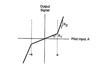
Figure 2-4 Example of command gain shaping for a nonlinear element.
Source: Kullberg and Elgcrona.40
Under limiting conditions, the FCS can sometimes remove the pilot from direct access to the control effectors in order to execute these functions. Thus, the auxiliary functions can become competitive rather than cooperative. FBW controls can further interrupt the pilot's connection with the aircraft's control surfaces by introducing features such as rate limiting. If not properly accommodated and coordinated, these functions and features of the FCS can lead to great uncertainties when the aircraft is operating at and near function or surface limiting conditions.
In conventional aircraft equipped with mechanical primary controls that operate the control surfaces through a fully powered surface actuation system (and no SAS), the pilot and the control surface are mechanically connected. There is little ambiguity about where the surface is relative to the cockpit control. This state of affairs is modified when dual functions are assigned to certain control surfaces. The most common examples are "elevons," "ailevators," and "tailerons," which combine longitudinal (i.e., pitch-axis) and lateral (i.e., roll-axis) control functions into one set of control surfaces. Therefore, when one or more of the surfaces is operating at or near its limits of position, rate, or acceleration, either longitudinal or lateral control functions must be given priority. Functional allocation and priority schemes, sometimes startling in mechanical complexity, are used to this day. Of course, the reason they almost always work effectively is that they were designed with exceptional foresight to provide adequate control power for contingencies. In all cases, however, present successes are also based on a past of overlooked possibilities, surprises, fortuitous "discoveries," and ad hoc fixes and developments. Sometimes even this relatively elementary sharing of controls
leads to major problems, including some of the so-called "three-dimensional PIOs" of Table 1-1.
The following APC events illustrate the kinds of problems that can occur. The first was encountered by a Tornado during a terrain-avoidance run.
During terrain-following flight a sequence of two autopilot actions near the ground were misinterpreted by the pilot, resulting in immediate counteractions by the pilot after deactivating the autopilot. At this point the APC was fully developed. The taileron became rate saturated. Compensating for a slow roll motion, the pilot command for differential tail was not fed through to the taileron due to internal CSAS [Command Stability Augmentation System] priorities giving the pitch axis priority over the roll axis. The pilot was finally trapped into a pitch/roll APC. Manual search along the CSAS switch/control panel took the pilot out of the loop.29
Thus, because the pitch axis had priority, the roll was not correctable, even though the pilot may have commanded proper inputs to compensate.
An excellent, well documented example of an ultimately non-oscillatory APC is the second JAS 39 accident listed in Table 1-2.
A time history of the second accident, which occurred during the public demonstration at the Stockholm Water Festival, is shown [in Figure 2-5]. The second accident featured a roll PIO consequent upon the pilot aggressively rolling to wings level to accelerate in front of the crowd watching the aircraft. The roll input was sufficient to drive the actuation to the deflection limit and shortly after the rate limit was reached. This caused the aircraft to roll more than expected, so the stick was reversed, driving well into the rate limiting [region] since the stick was demanding the limit of both deflection and rate. [Figure 2-6 shows]…the stick deflection in roll and pitch as a crossplot. With the rate limiting in effect, the inner stabilization loops were ineffective. Analysis has shown that the effective time delay between pitch stick and pitch acceleration response increased from less than 100 milliseconds to around 800 milliseconds. The subsequent response and pitch up to high angle of attack caused the pilot to eject after 5.9 seconds, fortunately without causing any harm to the crowds on the ground or the pilot.40
As this accident illustrates, APC problems may be complicated when additional functions share the pilot's direct authority over the control effectors.
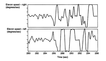
Figure 2-5 JAS 39 accident time history. Source: Kullberg and Elgcrona.40
Triggers
In most cases, severe PIOs are initiated by one or more stimuli acting as triggering events. These triggers typically excite an oscillation by altering a component of the closed-loop pilot-vehicle dynamics, resulting in an unstable or very lightly damped system.
A trigger may influence the pilot, the vehicle, or both. There may be a causal chain of trigger events in which one event initiates a series of secondary triggering events (e.g., a threat of collision that results in high-gain manual control). Triggers can originate in the external environment, the vehicle, or the pilot, but all triggers have the potential to result in adverse APC that leads to aircraft upsets. Three classes of triggers are discussed below: environmental triggers, vehicle triggers, and pilot triggers.
Environmental Triggers
Environmental triggers can initiate APC events in several ways. The most direct way is an environmental circumstance that requires destabilizing control actions. One example would be a threat of imminent collision that requires large-amplitude control actions, which may result in nonlinear control response. Another example of an environmental trigger is atmospheric turbulence. Turbulence at high altitude has been linked with several severe APC events in transport aircraft.
Environmental factors can also alter the pilot's dynamics. For example, an external threat may increase the pilot's stress level, with a resulting increase
in pilot gain. The external situation may also demand precision control that requires high-gain piloting, such as pitch control during landing.
Finally, environmental factors can sometimes alter the basic vehicle dynamics. For example, severe icing can alter both pitch and roll dynamics.
Vehicle Triggers
Vehicle-based triggering events most commonly involve changes in the effective aircraft dynamics that cause a mismatch between the pilot's control strategy and the aircraft dynamics. Three categories of vehicle-based triggers are discussed below.
Flight Control System-Aircraft Configuration Mismatches
A fairly common trigger, especially for a developmental PVS, is a miscalibrated FCS gain or other parameter change intended to adjust the FCS
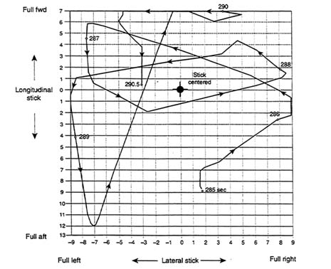
Figure 2-6 JAS 39 accident cross plot of stick deflection in roll and pitch during a roll PIO and unintended pitch up maneuver. Source: Kullberg and Elgcrona.40
properties as a function of the aircraft configuration. An example is the unanticipated level of the auto-speedbrake deployment in the Boeing 777 event (described in the Case Studies section of this chapter).
System failures
System failures can alter the effective aircraft dynamics either by changing the aircraft's response to control inputs or by changing the feedback to the pilot. Control system failures, such as failures in the hydraulic system, actuator failures, or uncontrolled changes in aircraft trim, may significantly compromise the controllability of the aircraft. Intermittent control system failures can result in highly nonlinear or discontinuous control responses that act as potential triggering events.
Sensor and display failures that alter the feedback dynamics to the pilot or the control system are also potential triggers. Even a simple mechanical failure, such as a loose pilot's seat, can alter the acceleration feedback the pilot receives and has been observed to trigger an APC event.
FCS Mode Shifts
Modern FCS technology significantly increases the ability of designers to tailor the effective aircraft dynamics for different tasks. However, it also has the potential to trigger APC events by allowing the flight control laws to change (i.e., switch modes) on the basis of numerous criteria, some of which may not be specified or understood by the pilot. If the pilot is unaware of the mode transition, a mismatch between the pilot's mental model and the effective aircraft dynamics can occur. The command path gain changes described earlier and exemplified by the YF-22 case study described later in this chapter are examples of this.
In FBW aircraft, the overall, effective response to pilot control input will depend on the inner-loop control laws and feedback gains programmed into the flight control computer. For a variety of reasons, these control laws may change during specific phases of a flight or flight conditions. For example, the ''response type" in some FCSs have longitudinal stick inputs that normally command changes in the flight path angle. However, during landing operations the response type is sometimes changed so that longitudinal stick inputs command elevator position, thereby making the touchdown handling qualities more conventional. Another example (noted earlier) is the control law for the Boeing 777, which changes between "air" mode and "ground" mode. Inner-loop control law and response type transitions are usually "task tailored" to improve handling qualities. Sometimes, however, it is difficult to anticipate
unusual situations where the control strategy is inconsistent with the pilot's intentions.
The lack of some inceptor-motion or other proprioceptive feedback in some FBW aircraft deprives the pilot of some "display" cues, and this lack of cues can, perhaps, trigger a Category II or III APC event. Rate limiting or other nonlinear control elements inserted after the pilot's command can introduce time lags that effectively disconnect the pilot from the aircraft, thereby leading the pilot to generate unreasonable inputs. The second JAS 39 accident discussed above is at least partly attributable to this problem.
Other new APC triggering mechanisms that have resulted from the extensive and common use of automation in modern aircraft stem from mixed-mode control. For some aircraft, it is common to fly in mixed manual and automatic control modes (e.g., pitch is controlled manually while speed is controlled by autothrottles). One mixed automation mode that has caused an APC event is the use of elevator trim for stability augmentation at high altitude. Elevator trim motions commanded by the SAS can interact with the pilot's manual inputs for controlling pitch, particularly in turbulent conditions.
Based on the available incident data, the potential for automation-related PIOs increases in situations where there is a sudden manual takeover from automated control, such as an autopilot disconnect in an out-of-trim condition. When pilots are in a supervisory status (i.e., out of the control loop), problems may arise if they are required to intervene suddenly. Slow response by the aircraft can result in inadequate control or over-control. Inappropriate mental models or incorrect situation assessment can lead to control actions that result in undesirable aircraft motion.
The manual takeover problem is exacerbated when the automation causes or masks significant changes in the underlying effective aircraft dynamics. In this case, the pilot is suddenly given a perhaps marginally stable aircraft to control. For example, degradation in lateral control during severe icing conditions is thought to have been the cause of the ATR 72 accident in Roselawn, Illinois, on October 31, 1994. The degradation was masked by the autopilot; when it was disconnected, the pilots were never able to regain stable flight. The manual takeover problem is an example of the "post-transition retention of pre-transition behavior." In this case, the transition is from automatic to manual control and the controlled element dynamics under manual control are not well modeled by the pilot.
In some cases, manual takeover problems have been combined with problems of mixed manual and automatic control modes. Examples include the China Airlines A 300-600 accident at Nagoya Airport near Tokyo on April 26, 1994, and the Tarom A 310-300 incident at Orly Airport in Paris on September 24, 1994. In the Nagoya event, the autopilot attempted to perform a go-around using the stabilizer trim while the crew attempted to fly the glide slope with the elevator. The resulting nose-up trim was so extreme that the aircraft pitched up uncontrollably when the pilot increased thrust. The accident
sequence started with the pilot manually flying the aircraft, although the flight director guidance system and autothrottles were engaged to maintain speed. During the approach, the pilot inadvertently activated the autopilot takeoff/go-around switch. Several seconds later, after the pilot noted that the switch had been activated, the autothrottles were disengaged, but the autopilots were then engaged, perhaps with the expectation that the autopilots would return the aircraft to the proper glide slope for approach. Instead, the autopilots used elevator trim to establish a large nose-up pitch consistent with a go-around. At the same time, the pilot attempted manually to get the nose down and return to the approach glide slope using control column commands to the elevators. By the time the pilot disconnected the autopilot and attempted a go-around, the aircraft was so out of trim that the aircraft reached a pitch angle of 52.6 degrees, slowed to 78 knots, and stalled at an altitude of 1,800 feet. The pilot was unable to regain control.61
Pilot Triggers
In many APC events, the precursor or trigger is pilot-related. Often an environmental or vehicle trigger precedes the pilot trigger, and the APC event results from an overreaction or lack of appropriate reaction on the part of the pilot.
Pilot gain often increases and can become excessive as a result of task-related or situation-related stress. The pilot's concentration on particular cues to the exclusion of others is often desirable. However, excessive exclusive concentration, called "tunneling," can lead to a momentary excessive gain and, subsequently, a pilot-triggered upset. Unexpected changes lead to the most severe situations. Pilot stress can be induced by an external threat that results in an adrenaline surge. Stress can also be task-induced when the pilot attempts a high-gain, high-stress task, such as aerial refueling or aircraft-carrier landing.
Pilot-triggered APC events can also be caused by inappropriate or incorrect control strategies. Pilot-triggered PIOs are common during initial pilot training when novice pilots attempt to control the aircraft using inappropriate control variables. For example, novice helicopter pilots often attempt (unsuccessfully) to hover by controlling position directly, rather than by controlling position indirectly through attitude. One of the basic objectives of flight training is for the pilot to identify the appropriate control variables to accomplish specific manual control tasks. During training, the pilot develops a mental model of the controlled element dynamics, which is used as a basis for control strategies.
Experienced pilots may use inappropriate control strategies if they do not fully understand or appreciate the situation or they are otherwise stressed. To carry the tunneling idea further, a pilot under stress may focus on an
inappropriate subset of the relevant control variables or may simply close the loop on the wrong variable.
As the complexity of modern FBW FCSs increases, the underlying effective aircraft dynamics can be task-tailored. The response type and dynamic characteristics are changed depending on a variety of criteria, such as phase of flight, airspeed, altitude, and flap settings. As the large number of potential flight-control response modes increases, so does the potential for a mismatch between the pilot's expectations of the effective aircraft dynamics and what the pilot actually experiences. If the automation is too complex, it may not be possible for the pilot to have an adequate mental model of the system. In the absence of a complete model, pilots develop ad hoc models of the effective aircraft dynamics based on nominal flight operations. In unusual or emergency situations, the pilot's ad hoc mental model of the aircraft FCS may lead to inappropriate control strategies and an increased potential for APC.
Case Studies Of Recent Aircraft-Pilot Coupling Events In Fly-By-Wire Systems
The following four sections describe APC events that illustrate the impact of adverse APC on developmental and operational aircraft. All four aircraft involved in these incidents used FBW FCSs. A fifth section discusses special considerations for APC events involving rotorcraft.
Case 1. Lockheed Martin/Boeing YF-22
The YF-22 is a test aircraft that was developed by Lockheed Martin and Boeing to demonstrate critical technology for the next-generation U.S. Air Force air superiority fighter. Flight testing was conducted in 1990. After the F-22 was selected for engineering and manufacturing development, additional flight evaluations were conducted on the YF-22 demonstrator aircraft in 1991 and 1992. The F-22 is scheduled for first flight in 1997.
Description of Event
On April 25, 1992, a YF-22 test aircraft was returning to Edwards Air Force Base after completing a test flight. As part of a planned photo session, the pilot performed an uneventful low approach and initiated a go-around, selecting military power and raising the landing gear. He then flew a closed pattern for a second low approach and initiated a second go-around, this time selecting afterburners. Upon raising the landing gear for the second go-around,
the aircraft began a series of pitch oscillations at an altitude of approximately 40 feet. After four or five oscillations, the aircraft impacted the runway. The pilot safely evacuated the aircraft after it came to a stop, but the aircraft was destroyed.
The flight data presented in Figure 2-7 indicate the following details of this PIO:
- The PIO frequency was approximately 0.67 Hz (4.2 rad/sec).
- Neither the horizontal tail nor the thrust-vectoring nozzles were position limited during the PIO, but they did exhibit extensive rate limiting.
- The horizontal tail reached a maximum deflection of approximately ±20 degrees, and it was rate limited at 60 degrees/sec.
- The thrust-vectoring nozzles reached a maximum deflection of approximately ±14 degrees, and they were rate limited at 40 degrees/sec.
- The aircraft experienced maximum pitch rates of approximately +17 degrees/sec and −26 degrees/sec, and maximum pitch acceleration of ±90 degrees/sec2.
- The response of the thrust-vectoring nozzle lagged behind the response of the horizontal tail by about 0.1 sec.
- There was no significant phase difference between the position of the thrust-vectoring nozzle and the pitch acceleration.
- The time difference between maxima (or minima) in pitch and pitch rate was approximately 0.45 sec. This corresponds to about 101 degrees, which is close to the expected 90 degrees (because the pitch rate is the derivative of pitch attitude for wings-level flight).
- The pitch rate lagged behind the horizontal tail position by approximately 92 degrees in the PIO. (This lag is expected to be about 90 degrees because the pitch acceleration is almost in phase with the horizontal tail, and pitch rate is simply the integration of pitch acceleration.)
Analysis
As with many APC events, the pilot initially thought that an aircraft failure had occurred. However, detailed analysis revealed that there had been no aircraft malfunction. Instead, it was determined that this event was triggered by an automatic change in pitch command gradients during the transition from gear-down to gear-up. This conclusion is substantiated by the flight recording for this accident. As illustrated in Figure 2-7, curve 2 shows a large increase in pitch rate response after the gear was raised at t = 2 sec.
Note that the large oscillations in pitch rate (curve 2), pitch attitude (curve 3), and normal acceleration (curve 4) start shortly after the gear is raised. The triangular wave appearance of curve 5, which depicts the position of the horizontal tail, indicates that the horizontal tail was essentially rate-limited throughout the event. In addition, the thrust-vectoring nozzle (curve 6) was also rate limited.
The YF-22 command gradients were largely developed in response to specific program objectives. For example, the thrust-vectoring control laws were optimized for high angle-of-attack flying qualities at high altitudes. In particular, the nose-down gradient was set to provide rapid nose-down recoveries from post-stall angles of attack.
The YF-22 control laws were not designed or analyzed for low-altitude, low-speed conditions with thrust vectoring engaged. Therefore, flight test procedures required that vectoring be turned off at low altitude. However, the flight test team did not comply with this restriction. Thus, on the second go-around, when the pilot raised the gear with thrust vectoring engaged, he unexpectedly encountered command gradients that were significantly larger than those intended for low-altitude, low-speed flight (see Figure 2-8). As a result of these large gradients, flight test data indicate that relatively small pitch stick movements by the pilot immediately prior to the PIO resulted in near-rate limiting of the horizontal tails. (A gain shift in the effective aircraft dynamics as a major source of the PIO is consistent with the analysis of command gain-shaping in Appendix C and in the section above on nonlinear, cliff-like PIOs). Thus, this PIO appears to involve the presence of (1) nonlinearities in the command path gain-shaping; and (2) nonlinear effects caused by rate limiting of the horizontal tail and the thrust-vectoring nozzle. The basic trigger was the unexpected change in pitch command gradients.
After the accident, the investigation team and the aircraft designers conducted separate evaluations of the YF-22 linear handling qualities metrics; the investigations conducted fast Fourier transform analyses to develop the pitch-attitude-to-pitch-stick frequency response* so that linear analysis such as the Aircraft-Bandwidth/Phase Delay, and Smith—Geddes Attitude-Dominant Type III criteria (see Chapter 6) could be used to determine the cause of the event. The linear analyses indicated that the YF-22 might have been susceptible to APC events with thrust vectoring engaged at low altitude. However, this conclusion has been questioned because of uncertainties about technical aspects of the analysis. For example, the coherence of the accident flight data used to generate the frequency response of the aircraft was not satisfactory because of the nonlinearity of the input signals and the rate limiting of the control surfaces.32
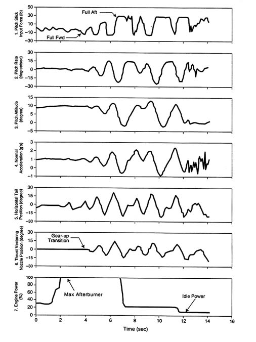
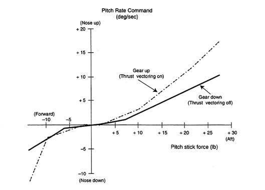
Figure 2-8 YF-22 pitch rate command stick gradients. Source: Harris.32
Post-Event Simulations
The accident review team attempted to recreate the YF-22 event using off-line and fixed-base pilot-in-the-loop simulators, but piloted simulations were unable to recreate the APC event.32
Case 2. Boeing 777
The Boeing 777 is a twin-engine, wide-body commercial transport with a typical seating capacity of 375. The 777 entered service in 1995, and as of January 1997, 45 aircraft had been delivered.
Description of Event
On July 24, 1994, during the thirty-fifth landing of the 777 developmental flight test program, a 777 airplane experienced an unusual PIO at the air-ground interface. Following touchdown, deployment of the auto-speedbrake
generated a vertical plunge and pitch down (see Figure 2-9, curve 3) that was checked by a rapid airplane-nose-up column input (Figure 2-9, curve 1). Airplane pitch response to this column input was excessive (Figure 2-9, curve 3) and caused the pilot to make a rapid airplane-nose-down column input. This cycle continued twice more before being terminated by a combination of intervention by the other pilot and nose gear contact with the runway. A similar incident (not shown) occurred later the same day following manual speedbrake deployment.
The flight data presented in Figure 2-9 indicate that the PIO frequency is 0.40 Hz (2.5 rad/sec) and the maximum travel of the elevators is approximately +25 degrees/−30 degrees. During the event, the elevators were rate limited at +40 degrees/sec to −45 degrees/sec, the aircraft experienced maximum pitch rates of approximately +3.9 degrees/sec and −6.1 degrees/sec; the time difference between elevator position and pitch maxima or minima was approximately 1.4 sec, which corresponds to a phase shift of 200 degrees; and the time difference between elevator position and pitch rate maxima or minima was approximately 0.6 sec, corresponding to a phase difference of 86 degrees.
Post-Event Flight Test and Simulation
As a result of the initial investigation into these incidents, the sequencing for on-ground speedbrake deployment was tuned to mitigate the plunge/pitch upset that had triggered them. Also, the management of the C*U integrator* in the elevator command path (see Figure 2-10) was modified to eliminate the delay observed when large-displacement column inputs reversed direction. A flight test investigation was then conducted to identify the source of the PIO susceptibility. The maneuver that was found most effective in reproducing the PIO behavior was on-runway attitude tracking. Following touchdown, the pilot was instructed to aggressively capture and hold a target pitch attitude on the primary flight display.
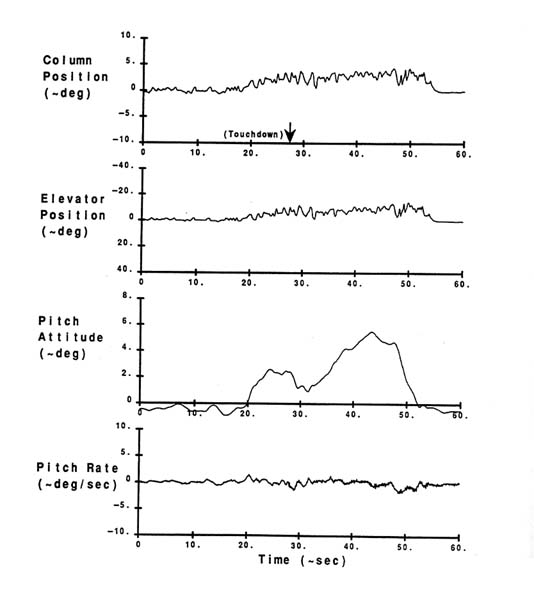
Figure 2-11 illustrates the first attempt to perform this maneuver in normal mode. A small Category I (linear) PIO developed when the pilot was closing the loop on pitch attitude, making the precision capture of a specified attitude extremely difficult. The maneuver was repeated in secondary mode and found to be much easier, with no unintended oscillations (Figure 2-12). Secondary mode pitch control consists of conventional column/elevator gearing with pitch rate feedback; the C*U terms in Figure 2-10 are not present. (During landing derotation in normal mode, the control law stays "in-air" until attitude passes below a specified threshold.) The results of these tests suggest that the C*U integrator terms were the prime contributors to the derotation instability; the speedbrake pitch/plunge upset was the trigger that caused the underlying Category I APC characteristic seen in this test to become a full-blown
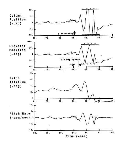
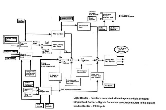
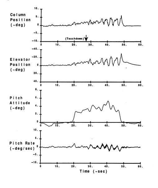
Figure 2-11 Time history for 777 attitude tracking on runway, baseline control law.
Source: McWha.47
Category II APC event. Normal acceleration cues sensed by the pilot may have aggravated the problem.
After the flight tests and subsequent analysis, piloted simulator, sessions were conducted in the 777 fixed-base simulator, which reproduced the characteristic shown in Figure 2-11. It should be noted that in the fixed-base simulator, the characteristic was manifested to the pilot in higher workload* and poorer task performance, not ''PIO." Further work led to a scheme to reduce the C*U integrator gain from a nominal value of 8.0 to 3.0 at touchdown. Validation of this scheme was conducted on the airplane, which repeated much of the earlier PIO investigation test conditions. In this test, normal mode on-runway attitude tracking was found to be significantly improved. Figure 2-13 illustrates the results of one portion of this test. In this example, the pilot progressively captured 7.5, then 6.0, then 5.0 degrees, with control considered positive throughout.
Implementation of a column feed forward command notch filter motivated a final round of tracking task tests, using the same on-runway maneuver described above. Figure 2-14 contains a time history showing two pilot captures of 6-degree pitch attitude. Again, control was considered positive.
Analysis
Spectral analysis was used to assess potential control law changes. Column-to-pitch rate and column-to-pitch attitude frequency response data for the four time histories shown in figures 2-11 through 2-14 are contained in Figure 2-15. The spectral analysis for these conditions was limited to the on-runway portion of the time histories, with the nose gear off the ground and the speedbrakes fully deployed. These data show significantly less bandwidth for the original normal mode configuration than with the secondary mode or the later normal mode configurations. Note that the 180-degree frequency for the original PIO-prone normal mode configuration is essentially the same as the observed PIO frequency in Figure 2-11.
Another way of looking at the pitch control system characteristics, which was found to be useful for on-ground operation, was to examine the net column-to-elevator gearing and phase behavior. Figure 2-16 contains column position to elevator position frequency response data from the same time histories. The original normal mode configuration is seen to have excessive gain at low frequencies, with significantly greater phase lag than the secondary mode or the later normal mode configurations. This additional elevator activity was caused by the C*U integrator acting at the original high-gain values.
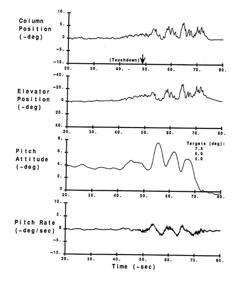
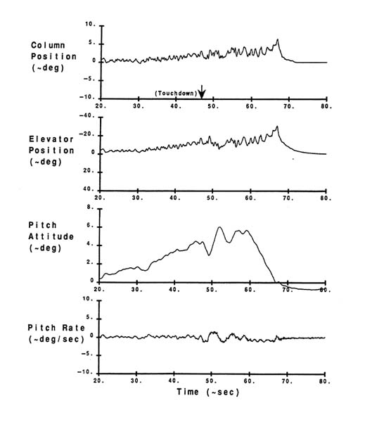
Figure 2-14 Time history for 777 attitude tracking on runway, revised control law plus command filter.
Source: McWha.47
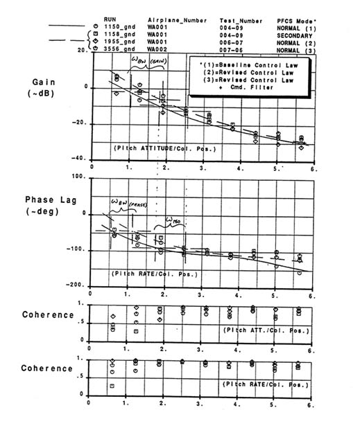
Figure 2-15 Bandwidth criteria applied to landing derotation, effect of 777 control law changes on pitch attitude/column position frequency response.
Source: McWha.47
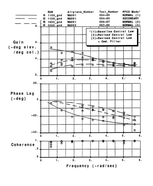
Figure 2-16 Elevator/column gain and phase, effect of 777 control law changes on landing derotation.
Source: McWha.47
Conclusions
The incident described above was a classic Category II PIO, with large-amplitude pilot inputs and both rate- and position-limited elevator activity (as indicated by curve 2 of Figure 2-9). Because of the air-to-ground transition aspects of these incidents (involving airplane, control laws, and pilot), a case could also be made that this was a Category III event.
Landing and derotation is a time of high pilot urgency and gain. For this reason it was assumed during control law development that fixed-base piloted simulations would not be adequate for realistic evaluation in this regime. One lesson from this event is that pilot urgency can be replaced to a significant extent by artificially boosting pilot gain via a suitable tight-tracking task. For example, on-runway attitude tracking showed clear trends in the time history and associated frequency response data. Derotation is a key flight phase and deserves special attention in preflight evaluation. The 777 simulator had the same characteristic as the airplane but was not evaluated as effectively prior to flight test. Also, none of the first five flight test pilots experienced any difficulty during landing, thus illustrating the need for carefully designed flight tests by as many different pilots as possible.
Case 3. McDonnell-Douglas C-17
The C-17 is a four-engine military transport aircraft with a quadruply redundant FBW control system. The aircraft can deliver cargo to austere airfields and land on unpaved runways.
Description of Event
On June 22, 1993, during mission number 176 of the C-17 flight test program, test aircraft T1 experienced a lateral APC event. The test was an approach to landing with hydraulic system #2 inoperative. On final approach, as the pilot corrected for crosswinds using rudders (at about 2 seconds, curve 2, Figure 2-17), he experienced a wing rock. The pilot initiated a lateral command to correct for the wing rock and entered a cycle of oscillatory lateral commands (3 to 12 seconds, curve 1, Figure 2-17). When the aircraft neared 10 degrees of roll attitude, right wing down (at about 8 seconds, curve 1, Figure 2-18) at approximately 15 feet from the ground (curve 3, Figure 2-18) the co-pilot initiated corrective action and attempted commands opposite to the pilot for two cycles (curve 1, Figure 2-17). The aircraft was finally stabilized and a go-around was initiated.
The APC frequency (pilot) was about 0.5 Hz (3.14 rad/Hz) (curve 1, Figure 2-17). During this event, the maximum aileron command was +26
degrees/−39 degrees, as was the actual maximum position of the right aileron (curves 3 and 4, Figure 2-17). The ailerons were rate limited at ±37 degrees/sec (curves 3 and 4, Figure 2-17). Maximum roll attitudes were +10 degrees/−6 degrees (curve 1, Figure 2-18), and maximum roll rates, were +14 degrees/sec /−16 degrees/sec (curve 2, Figure 2-18).
Analysis
Analysis showed that the APC event was caused by rate limiting of the ailerons. The rate limiting was caused by overcommanding the surfaces. The overcommand was caused by high gains on both the pilot command path and the feedback paths.
Corrective Action
The total lateral loop gain was reduced, thereby reducing the magnitude of aileron commands for the same stick movement. The overall phase lag of the system was also reduced by optimizing the existing structural filters and removing unnecessary filtering. The use of ailerons was reduced by using spoilers for manual commands only and continuing the use of ailerons for both commands and automated stability augmentation.
Case 4. Airbus A 320
The Airbus A 320 is a twin-engine narrow-body commercial transport with a typical seating capacity of 150. The A 320 entered service in 1988, and approximately 560 A 320s and A 321s are currently in service. (The A 321 is a stretched version of the A 320.)
Description of Event
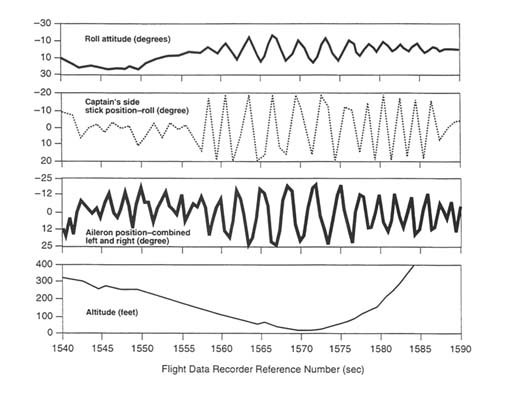
On April 27, 1995, at about 5:30 p.m. local time, an Airbus A 320 operated by Northwest Airlines was approaching runway 18 at Washington National Airport. Winds were from 220 degrees at 17 knots, gusting to 25 knots. At an altitude of 140 feet, the airplane began a series of roll oscillations that persisted for 30 seconds, reaching a maximum roll of about ±15 degrees (see Figure 2-19, curve 1). Approximately 12 seconds after the start of the roll oscillations, at an altitude of less than 50 feet, the crew initiated a missed approach procedure. The aircraft subsequently made a successful landing. No injuries were reported, and the aircraft was not damaged.
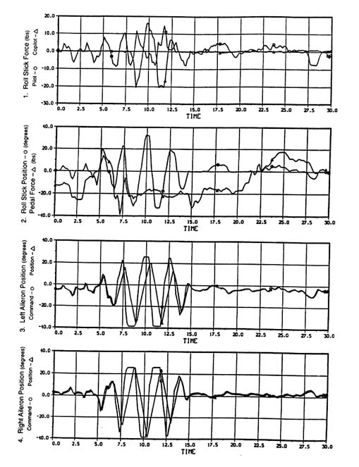
Figure 2-17 C-17 test aircraft lateral oscillations during approach to landing with hydraulic system #2 inoperative.
Source: Kendall.38
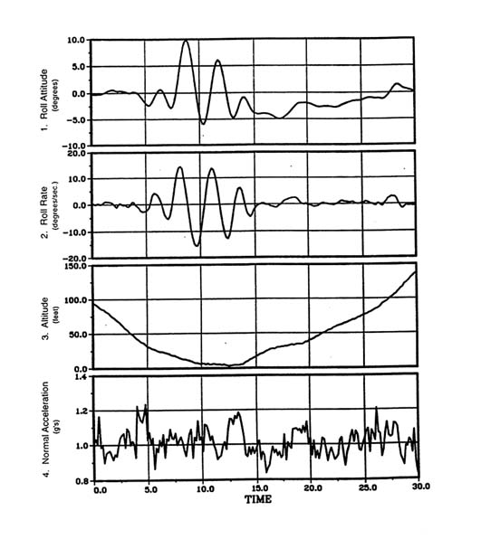
Figure 2-18 C-17 test aircraft lateral oscillations during approach to landing with hydraulic system #2 inoperative, continued.
Source: Kendall.38
As this is an operational airplane, the flight data presented in Figure 2-19 suffer from sampling limitations associated with the data recorder. However, the approximate estimates that can be made indicate the following:
- The PIO frequency was approximately 0.31 Hz (2.5 rad/sec).
- The ailerons achieved maximum deflection of approximately +24 degrees/−20 degrees, and they achieved maximum deflection rates of 35 to 40 degrees/sec.
- The aircraft experienced maximum rolls of approximately +15 degrees (right wing down) and −16 degrees (left wing down). (The National Transportation Safety Board [NTSB] reported a maximum roll of +12.3 degrees/−15.3 degrees.)
- The aircraft experienced maximum roll rates of +23 and −24 degrees/sec.
- During the maximum rolls, the phase difference between stick position (in roll) and aileron position was approximately 216 degrees.
- During the maximum rolls, the phase difference between aileron position and roll was approximately 144 degrees.
Analysis
Data from the flight data recorder (FDR) indicate that, after performing the final turn to align with the runway, the captain made a series of 12 large, rapid, cyclic deflections on his sidestick controller. Most of the deflections were to the maximum values allowed by the mechanical stops on the controller (±20 degrees) (see Figure 2-19, curve 2). Although the pilot had reported experiencing an uncommanded roll of 30 degrees, data from the FDR indicated that aircraft control surfaces operated normally. The NTSB subsequently concluded that this incident was consistent with a PIO and that it was not the result of an uncommanded roll.52
During the approach, the flaps were deflected to the 20-degree position, (which is referred to as the CONF 3 position) as part of a noise abatement procedure. Prior to this incident, there had been approximately 10 similar incidents involving other A 320s. In each case, aircraft were landing in gusty wind conditions with flaps in CONF 3, and some pilots experienced difficulty maintaining lateral control. Airbus initially responded to these incidents by issuing a temporary revision to its flight crew operating manual recommending that flaps be set at full deflection (35 degrees, which is referred to as CONF FULL) whenever possible during turbulent landing conditions, to reduce the workload when flying manually. Airbus then developed a flight control software modification to improve the PIO characteristics of the A 320 in CONF 3. This modification reduced the sensitivity of the aircraft to lateral sidestick inputs.
Although the Airbus service bulletin did not clearly indicate that the modification made important improvements in the handling qualities of the A 320 in CONF 3, Airbus promulgated the information widely. However, neither the French certificating authority (Direction Generale de l'Aviation Civile) nor the FAA made it mandatory. As a result, various A 320 operators handled the matter differently. Some airlines, especially European airlines, disseminated the recommendations and incorporated the modification. Others, including Northwest Airlines, did not. Consequently the aircraft involved in this incident had not been modified, and the pilots were unaware of the Airbus recommendation to use CONF FULL rather than CONF 3 in turbulent conditions. After the event, Northwest Airlines voluntarily installed the modification on all of its A 320s, and subsequently installation of the modification was made mandatory. Operators have reported no problems since incorporating these changes.
Conclusions
Although this problem was corrected by procedural changes and software modifications, the committee concludes that this PIO was probably associated with the lateral flying qualities of the A 320 with flaps in the CONF 3 position. It was probably triggered by a wind gust as the pilot was completing his final turn prior to landing. This incident illustrates that information on APC problems (and solutions) is not always effectively disseminated to the pilots who need it. In fact, incidents such as this one that do not involve injuries or equipment damage often escape scrutiny by government agencies. As a result, unless there are multiple incidents or a serious accident occurs, relevant issues may not be fully resolved.
Case 5. Special Considerations for Rotorcraft
Rotorcraft (i.e., helicopters and tilt rotors such as the V-22 Osprey) have several characteristics that make them prone to PIO:
- limited stability
- significant delays in control effectors because of the time required for rotor response (typically 70 msec) and power actuation (20 to 30 msec)
- coupling of rigid body modes with rotor and transmission modes
- significant inherent cross-coupling of control that is highly nonlinear
- potential coupling with external slung loads
FBW technology has only recently been incorporated into rotorcraft (e.g., V-22, RAH-66 Comanche, and NH-90). Thus, there has been relatively little opportunity to encounter FBW-related PIOs in rotorcraft. However, experience with research helicopters, which is described below, shows that there is reason for caution if not concern.
FBW on rotorcraft can add delays to the FCS response time because of stick filtering and control law computation. For example, one FBW technology demonstrator aircraft (the Advanced Digital Optical Control System, ADOCS) exhibited PIOs in several high gain tasks, including vertical landing, dart-quickstop, and slope landing. End-to-end delays occurred as shown in Figure 2-20. A time history for a landing task is shown in Figure 2-21.67
A second example demonstrating the potential for rotorcraft PIOs occurred in an in-flight simulator.7 The command model was attitude command for pitch and roll; the yaw axis had heading hold. The pilot's inceptors consisted of a spring-loaded force feel system with very little damping, linear stick forces, and relatively low breakout forces.
Another test used a lateral-position tracking task. A hover board mounted on a target vehicle was used to guide the helicopter into a hover over a given point at a given altitude (Figure 2-22). The lateral hover tolerance was ±3 m,
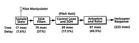
Figure 2-20 Response time analysis for the advanced digital optical control system demonstrator. Source: Hamel.30
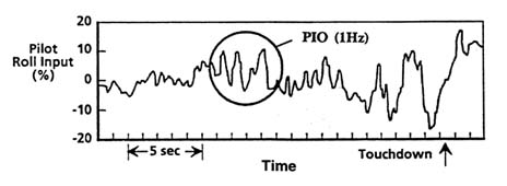
Figure 2-21
Sample time history for a rotorcraft vertical landing task. Source: Hamel.30
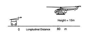
Figure 2-22 Schematic drawing of a helicopter tracking a vehicle-mounted hover board. Source: Ockier.56
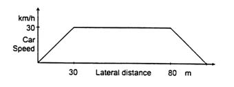
Figure 2-23 Helicopter lateral-position tracking task, velocity profile for the lateral vehicle displacement. Ockier.56
and the horizontal tolerance was ± 1.5 m. The task was to maintain the hover position relative to the hover board while the target vehicle moved a distance of 100 m in 20 seconds using the velocity pattern shown in Figure 2-23. At the end of the maneuver, a stabilized hover was to be regained.
Figure 2-24 shows the lateral stick input and the bank angle response for the lateral-position tracking task. With no time delay added to the inherent helicopter dynamics (τ = 90 msec), the attitude command model gave a bandwidth of 2.6 rad/sec and a phase delay of 0.1 sec. Although the response is not free of oscillations, there is no PIO tendency and the task was rated as having a CH PR (Cooper-Harper Pilot Rating)* of 5.
Figure 2-25 shows the lateral stick input and bank angle for the same attitude command model with an added time delay of 100 msec (so that τ = 190 msec), resulting in a bandwidth of 2.2 rad/sec and a phase delay of 0.17 sec. A very clear PIO tendency can now be recognized, and the configuration was rated as having a CH PR of 7. Although the time delay is a partial reason for the PIO, there may also be a more important contributor—the biomechanical coupling between aircraft and stick/pilot.
Figure 2-26 shows the two command systems versus the ADS-33D requirement for hover and low speed aggressive maneuvering.68 The second (PIO-prone) configuration is incorrectly predicted to have Level 2 handling qualities (''adequate to accomplish the mission flight phase, but some increase
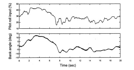
Figure 2-24 Time history of the helicopter lateral-position tracking task with no added time delay. Source: Ockier.56
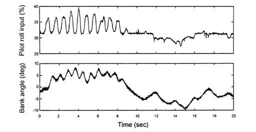
Figure 2-25 Time history of the helicopter lateral-position tracking task with 100 msec of added time delay. Source: Ockier.56
in pilot workload … exists"71). This discrepancy underlines the fact that other effects, such as the (biomechanical) aircraft-stick/pilot coupling may have an impact on the introduction of this particular PIO. Such effects are not included in any of the current criteria and would certainly be difficult to predict. It also
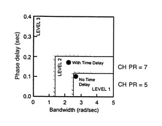
Figure 2-26 Small-amplitude handling qualities criterion (target acquisition and tracking) from ADS-33D.
Source: Ockier.56
illustrates the importance of appropriate force-feel systems for helicopter handling qualities and for the onset of PIOs. For helicopters flying with an attitude command system, additional damping, rapid follow-up trim, or even active, non-linear controllers may be necessary.56
A comprehensive review of rotorcraft-pilot coupling potential and experience, including the two cases outlined above, has recently been published.30


