
Appendix B
Modern Sensor Technology
This appendix presents several examples of sensors that would be particularly sensitive to the parameters that might change in concrete during processing and setting.
Figure B-1 shows a densitometer/viscometer for measuring the density and viscosity of a fluid. Although the sketch of the prototype shown in this figure was originally developed to measure the density and viscosity of oil, it could easily be modified to measure the density and viscosity of unset concrete. This would allow such measurements to be made in situ and in line for concrete in the mixing and pumping equipment. In this device, the response of the high-frequency electrodes on the rough resonator differs from the smooth resonator as a function of the viscosity and density of the fluid. Given calibration data, viscosity and density can be measured. The RTD measures temperature to accommodate for density and viscosity changes with temperature.
Figure B-2 shows a sensor based on a Surface Acoustic Wave (SAW) device. In a SAW, the input electrode is oscillated at a high frequency. The mechanical wave created by the electrode is transmitted across the surface of the SAW and received by the other electrode. If the nature of the surface across which the wave is transmitted changes, the amplitude and frequency of the wave will be altered. Typically, a selective film is deposited on the surface that absorbs/adsorbs only a limited number of chemical species. The adsorption/absorption of these species will change the characteristics of the transmitted wave. A variety of films could be used to sense various components in the concrete. For example, films sensitive to pH could be made.
Measuring a certain parameter on a small cheap sensor is only half of the desired total functionality. It is desirable to perform some, if not all, of the data processing on the chip. This creates an integrated microsystem. Properly configured, the microsystem will process and digitize the data and pass it into a network. Figure B-3 shows an example of an integrated sensor designed to detect hydrogen gas.
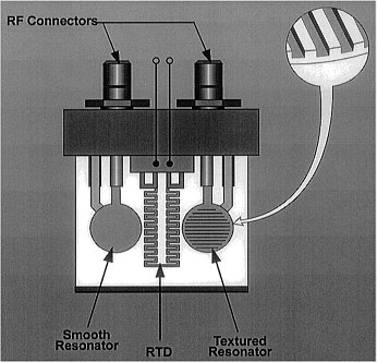
FIGURE B-1 The Sandia densitometer/viscometer. Source: Martin et al, 1994. Reprinted with kind permission from Elsevier Science S.A., P.O. Box 564, 1001 Lausanne, Switzerland.
In some applications, it may not be possible to place the sensor at the desired location, regardless of its miniaturized size. In such cases, it is possible to construct a sensor that senses remotely, as shown in Figure B-4. This particular sensor is designed to detect gaseous species, but it could be constructed to detect liquids as well. The optical fiber has a thin layer of reflective materials, often a metal, deposited onto the end. The film has an intrinsic reflectivity, and light transmitted down the fiber is reflected back up the fiber to a photodetector. If a chemical species is absorbed/adsorbed onto the film, the reflectivity will be changed and measured. Given the proper calibrations, chemical composition can be determined. In this case, it would be possible to embed the sensor in setting concrete so that the cure could be observed and appropriate environmental adjustments made.
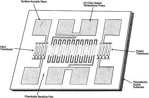
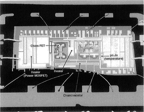
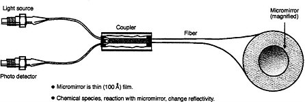
FIGURE B-4 Micromirror sensor. Source: Butler, 1994. Reprinted with kind permission from Elsevier Science S.A., P.O. Box 564, 1001 Lausanne, Switzerland.
REFERENCES
Butler, M.A. 1994. Micromirror optical-fiber hydrogen sensor. Sensors and Actuators B 22(1994):155–163.
Martin, S.J., G.C. Frye, and K.O. Wessendorf. 1994. Sensing liquid properties with thickness-shear mode resonators. Sensors and Actuators A 44(1994):209–218.
Rodriguez, J.L., R.C. Hughes, W.T. Corbett, and P.J. McWhorter. 1992. Robust, wide range hydrogen sensor. IEDM Technical Digest 1992:521–524.


