
limit has been a design constraint, because the diminished modulus causes stress amplification. An illustration is presented for a drum rotor [63] (Figure 12). Transverse stresses are induced by the rotations. When these exceed the elastic limit of the TMC closest to the center of rotation, the hoop stresses increase on the remainder of the TMC. This stress elevation causes the UTS to be reached at lower rotational velocities as σ e diminishes. This factor is of particular concern upon thermal cycling. Beyond a thermal range ∆Tc, dependent on the transverse stress, rachetting occurs [13] and the residual stress decreases, causing σe to diminish and eventually approach zero. This phenomenon results in a maximum temperature range allowing shakedown [13], plotted in Figure 13 .
The transverse responses in CMCs are quite different. The major concern is delamination, particularly in attachments and transitions [31, 64-66] (Figure 14). There are two motivating forces: one caused by the loads and the other by the heat flux [66]. Manufacturing flaws interact with these forces to initiate cracks, which then extend along interlaminar planes. Usually, the delaminations arrest, because they extend into regions that diminish the energy release rate. Some load-bearing capacity is thus retained [31]. The noncatastrophic nature of delamination is an attribute, but the remanent load-bearing capacity is small. Designing to this remanent strength would lead to excessive mass in the attachments and transitions. This factor requires that designs be made based on the initiation loads. Then, the key issue is that delaminations initiate subject to weakest-link scaling, with extreme variability arising from manufacturing flaws; that is, in this orientation, CMC performance is dominated by the low toughness matrix.
Manufacturing flaws and other transverse cracks induce local temperature variations. The temperature gradients create an energy release rate, through the thermal strains, even when there are no applied loads. This phenomenon has a steady state, wherein the energy release rate is independent of the flaw size. The steady state result is [67]
EGs/H(α∆T)2= λ(h/H) (13)
where H is the CMC thickness, ∆To the temperature drop through the CMC, h the flaw location, and λ the function plotted in Figure 15 . Thermal delamination occurs when Gs reaches the matrix toughness, Γm.
The design implications are so debilitating that a delamination strategy is needed to enable successful implementation. There are no evident mechanisms for elevating the matrix toughness, subject to the constraints of affordable processing. Moreover, there are only limited means for ameliorating the manufacturing flaws. A preferred approach is to use braiding or cross stitching of the fibers in the attachments and in sections subject to high heat flux. The fibers that cross over the delamination plane have a major effect on the transverse toughness, through large-scale bridging [65]. Order-of-magnitude improvements in toughness are induced by a relatively small fraction of fibers (< 0.1) in the thickness orientation [67]. While the benefits are clear, there has been minimal technical progress. The limitation has been the difficulty in weaving ceramic fibers with high modulus into the required configurations, without either fracturing or inducing large bending stresses.
LIFE-LIMITING MECHANISMS
Fatigue
Cyclic degradation occurs in both CMCs and TMCs [23, 68-72]. At ambient temperature the degradation is minimal for CMCs but substantial for TMCs—a consequence of their relative notch sensitivities [71]. However, CMCs have problems at intermediate temperatures, where corrosion fa-
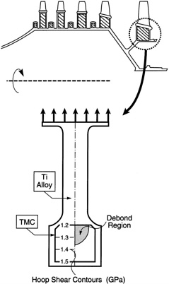
FIGURE 12 FEM calculations for a drum rotor with a TMC annulus. The debonded regions within the TMC, caused by the transverse loads, are indicated on the right, while the hoop stresses in the TMC are on the left. Note that debonding has elevated the hoop stresses in neighboring regions of the TMC. These stresses would cause premature failure.
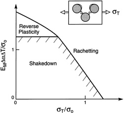
FIGURE 13 The shakedown and ratchetting regions in a TMC subject to transverse loads, σT, and cyclic temperature, ∆T: here, σo is the matrix yield strength. SOURCE: Reprinted (modified) from Jansson and Leckie (1994) [32], copyright 1994, with permission from Elsevier Science.
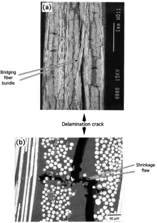
FIGURE 14 Delaminations induced in I-sections by applied bending moments. The load deflection response is indicated. SOURCE: Reprinted from Heredia et al. (1996) [31], copyright 1996, with permission from Elsevier Science.
tigue mechanisms operate, as elaborated in the following section on corrosion fatigue [73]. Composites are subject to a diminishing friction stress upon load cycling. The changes can be diagnosed by using hysteresis loop measurements [68] (Figure 16). The reductions in τ are attributed to interface wear. This process is not understood, but it exhibits a limiting friction, τs [23]. The diminished τ increases the stress intensity range at the matrix crack tip, ∆Ktip [70,71], as well as the mean value, ![]() tip. The consequences differ for TMCs and CMCs. For TMCs, the ∆Ktip causes the crack to extend in accordance with a Paris Law [70] (see Figure 16). But even though τ diminishes and increases ∆Ktip, the crack growth rates are considerably lower than those for the monolithic alloy, because of the strong fiber bridging (LSB) effect [70,71]. The principal problem arises from the notch sensitivity of TMCs, because they are embedded within a monolith. The TMC is subject to residual compression, whereas the monolith is in tension. This increases the R-ratio in the monolith, which accelerates crack formation. Should such a crack extend through the monolith and penetrate the TMC, the composite notch sensitiv-
tip. The consequences differ for TMCs and CMCs. For TMCs, the ∆Ktip causes the crack to extend in accordance with a Paris Law [70] (see Figure 16). But even though τ diminishes and increases ∆Ktip, the crack growth rates are considerably lower than those for the monolithic alloy, because of the strong fiber bridging (LSB) effect [70,71]. The principal problem arises from the notch sensitivity of TMCs, because they are embedded within a monolith. The TMC is subject to residual compression, whereas the monolith is in tension. This increases the R-ratio in the monolith, which accelerates crack formation. Should such a crack extend through the monolith and penetrate the TMC, the composite notch sensitiv-
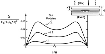
FIGURE 15 Delamination caused by a through-thickness thermal gradient in a CMC. Also shown are the steady-state energy release rates. Here ∆To is the temperature difference across the CMC, and α is its thermal expansion coefficient.
ity would become a factor [23]. The implications become apparent upon equating the monolith thickness, h, to the notch size, and the peak stress, σmax, to that from the combined residual and cyclic stresses. When h and σmax are small, the stresses on the fibers in the TMC never reach their UTS and the cracks extend benignly, only in the matrix. Conversely, at larger stresses, the outer fibers in the TMC fail. This causes the entire bridging zone to rupture, resulting in rapid crack acceleration. This fiber failure transition thus represents a design limit, or threshold. Life prediction methods require that the parameters governing the fatigue limit are manufacturing-insensitive and well-controlled.
For CMCs, there is no mechanism for cyclic growth of matrix cracks. A more important factor is the increase in ![]() tip, which causes cracks to extend upon reaching the matrix toughness [68,69]. However, this is a benign phenomenon, since matrix cracking is stable and, moreover, is the source of the inelastic strain that imparts stress redistribution capacity to the material.
tip, which causes cracks to extend upon reaching the matrix toughness [68,69]. However, this is a benign phenomenon, since matrix cracking is stable and, moreover, is the source of the inelastic strain that imparts stress redistribution capacity to the material.
Corrosion Fatigue
High-temperature forms of stress corrosion with attendant embrittlement pose major materials development and life prediction challenges [73,74]. When one or more material constituent is susceptible to oxidation, a rapid degradation in performance may ensue, particularly when the process is accelerated by stress. The clearest illustration is oxidation embrittlement in nonoxide CMCs. In this case, oxidation decreases the fiber strength and increases the interface friction stress. These effects act synergistically to cause premature fiber failure at small cracks in the matrix. The consequence is rapid crack growth, with diminished crack “blunting,” resulting in low rupture life. The behavior has all of the characteristics exhibited by stress corrosion, with the active species now being oxygen. The phenomenon is illustrated in Figure 17 .
Matrix cracks created upon loading become pathways for the relatively rapid ingress of oxygen. The oxygen reacts to form solid and gaseous products. There is a threshold stress below which the phenomenon does not occur, given by [74]
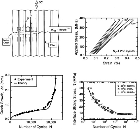
FIGURE 16 Cyclic loading effects found in TMCs. There are changes in the friction stress diagnosed by using hysteresis loops. But the crack growth rates are still much lower than those in the matrix without the fibers.
This stress is typically small, of order 10 to 15 MPa, and too low to enable efficient, lightweight design. Degradation when σ < Sth occurs according to two rate-limiting phenomena. (i) When the oxygen flow within the cracks is relatively rapid, all reinforcements bridging surface-connected cracks oxidize and weaken simultaneously. When they have degraded sufficiently to fail, the surface cracks extend across the weakened zone and form new crack segments bridged by pristine reinforcements (see Figure 17). This new bridged region again gradually weakens and fails. The process continues in a manner resembling reaction-controlled stress corrosion cracking. This is the more important regime, because it governs the rupture life at long times. (ii) When the matrix crack opening is narrow, oxygen gradients develop along the crack, resulting in a degradation front that progresses into the material. This process is similar to diffusion-controlled stress corrosion cracking.
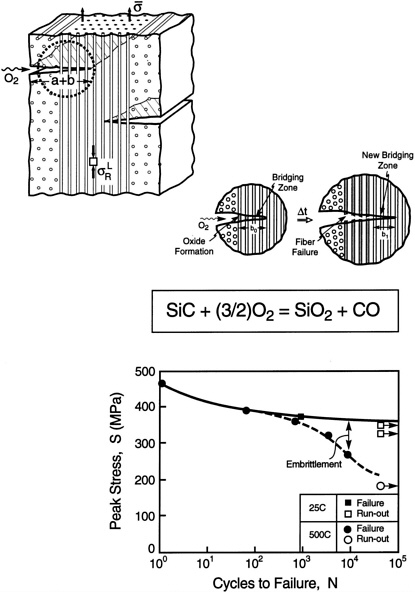
FIGURE 17 A schematic illustrating the stress oxidation effect. Oxygen penetrates the material through the matrix cracks. Local oxidation interacts with the stress concentrations on the fibers to diminish their failure strength, causing the fibers to fail at the matrix crack. This process repeats, and the crack extends in a manner analogous to stress corrosion. SOURCE: Reprinted (modified) from Evans et al. (1997) [75], with permission from the American Ceramic Society.


