
5
Integrated Aircraft
This chapter concentrates on technology and systems integration—combining disparate units into a unified whole to achieve a common goal.1 The biggest systems integration challenge faced by the HSR Program is designing an integrated aircraft with acceptable flight dynamics and handling qualities. Achieving this goal requires overcoming adverse interactions involving the pilot, airframe, propulsion system, and flight control system. This report refers collectively to the last three as the APSE (aero/propulsive/servo/elastic) system.
Additional challenges are associated with the flight deck system (particularly with regard to the external visibility system [XVS]), community noise requirements (because minimizing noise involves design of the airframe, flight control system, and propulsion system), certification (because the FAA and industry need to understand how to certificate an aircraft that incorporates the advanced technologies being developed by the HSR Program), and aircraft operations (to examine the impact of HSCT characteristics, such as length, wingspan, and speed, on airline, airport, and air traffic control facilities and operations). Many of these integration issues are exceedingly complex, and final resolution will require inflight testing (which would occur during the advanced technology demonstration phase recommended by the committee).
|
1 |
Additional information on program planning issues associated with systems integration appears in Chapter 6. |
SYSTEMS INTEGRATION, FLIGHT DYNAMICS, AND CONTROL
Background
The design of the TCA, which is representative of the HSCT designs currently envisioned by NASA and industry, specify a very large aircraft. The structural weight and aerodynamic drag of this aircraft must be minimized to meet the flight performance requirements established by the HSR Program. As a result, aerodynamic stabilizing surfaces (such as the horizontal stabilizer) will be relatively small, and the vehicle will be dynamically unstable in one or both axes over at least a portion of the flight envelope. Thus, the flight control system will need to include high-authority, multiloop feedback control systems, both for basic attitude stabilization and for tailoring the vehicle's dynamic responses. This tailoring must deliver maximum range performance, superior handling characteristics, and excellent ride qualities.
The large size of the HSCT will also result in structural vibration mode frequencies2 lower than for any existing aircraft. In fact some vibration frequencies will be within the bandwidth of the pilot and the flight control system. Hence, dynamic interactions between rigid-body and elastic responses of the airframe will be significant; piloted, ground-based simulations have already verified that these interactions will have an enormous and unfavorable impact on HSCT handling characteristics (Waszak, Davidson, and Schmidt, 1987; Coleman, 1996). Furthermore, these low-frequency elastic effects can lead to catastrophic pilot-vehicle dynamic coupling, and even low levels can produce unacceptable passenger discomfort. However, there is a dearth of flight-control design criteria (flying qualities criteria) for highly elastic aircraft, which further complicates the design challenge.
Gain stabilization3 of low-frequency structural vibration mode frequencies will not be possible because of fundamental limitations on the achievable performance of feedback systems. (For the HSCT, the essential problem is the small difference in frequency between the unstable attitude mode4 and the lowest structural vibration mode frequency, as shown schematically in Figure 5-1.) As a result, some active structural mode control5 will be necessary. This mode control system would be in addition to any other higher-frequency active flutter-suppression system that may be required.
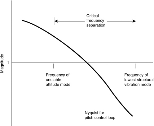
FIGURE 5-1
Difference in frequency between unstable attitude mode and the lowest structural vibration mode frequency of the TCA design.
Another area of concern is the amount of flow distortion at the engine inlets caused by non-zero side-slip angle or angle of attack. This distortion can induce an engine unstart.6 The sudden loss of thrust caused by an engine unstart would cause additional excursions in side-slip angle and angle of attack, possibly causing other engines to unstart. To avoid this, either flow distortion must be regulated or the response of the aircraft to an unstart must be tightly controlled. In the event of an unstart, the ability to provide the necessary control depends a great deal on both the integrated feedback-system design and the magnitude of elastic deformations of the aircraft structure following the disturbance created by an unstart. A recent simulation study of an HSCT-like vehicle concluded that ''structural flexibility effects are expected to be significant for aircraft controllability during unstarts'' (Shelton and Harris, 1994).
|
6 |
See Box 3-1 for an explanation of engine unstart. |
Aero/Propulsive/Servo/Elastic Phenomenon
Integration of the HSCT airframe, propulsion system, and flight control system produces a highly interactive multidisciplinary dynamic system, herein referred to as the APSE (aero/propulsive/servo/elastic) system. The ability of the flight crew to control the APSE system requires a tightly integrated flight-management/flight-control/propulsion-control system. Developing and certifying such a system is completely outside industry's experience base. Existing vehicles are either aerodynamically stable (e.g., the Concorde and B-1) or much smaller and rigid, with much higher structural vibration mode frequencies (e.g., fighter aircraft). HSCTs will be both unstable and highly flexible, with very low mode frequencies. This combination creates an incredibly difficult technical and organizational challenge.
Industry's limited experience base is not the only problem. The effort required to resolve APSE problems is huge and requires the close integration of a wide variety of technologies and organizations within the HSR Program. Flight-control design criteria are virtually nonexistent for highly flexible vehicles, and it is physically impossible to make a flexible structure behave dynamically as if it were rigid. In addition, the frequency spread between the TCA's unstable attitude mode and its first elastic mode may be too small to create a safe and effective control system because of a fundamental limitation on feedback control systems (i.e., Bode's integral). As a consequence, it is possible that the APSE system incorporated in the TCA may have design requirements for dynamic performance and stability robustness that are unattainable.
In other words, the structural flexibility of the TCA design simply may be too great. If this is true, (1) the flight control design requirements must be relaxed (e.g., to reduce the stability gain/phase margins7), which would make certification more difficult; (2) the level of aerodynamic instability must be reduced, which would reduce cruise L/D—perhaps as much as 4 percent; and/or (3) structural stiffness must be increased, which would almost certainly lead to an unacceptable increase in structural weight. For example, increasing stiffness enough to produce structural vibration mode frequencies similar to the B-1 would probably more than double the structural weight of the TCA design. In any case, the efficacy of the TCA design would be severely diminished. The committee believes that this is an area of significant technical risk and urges the HSR Program to develop and implement appropriate risk abatement strategies (including full-scale flight tests during the proposed advanced technology demonstration phase).
The HSR Program seems to perceive flight control and flight management as an area of low risk. For example, the HSR Program's list of top-level enabling
technologies (see Figure 1-1) does not include the development of analysis and design tools, techniques, or criteria applicable to dynamic control of a highly interactive aircraft design. Furthermore, structural-dynamic effects and APSE interactions were not included in either the process used to select the TCA design configuration or the piloted simulations used to define the desired dynamic characteristics of and specifications for the flight control system. As a result, the committee believes that the current TCA configuration does not adequately address APSE effects.
Although APSE effects may be of great concern to some members of the HSR flight-control technical community, control-law design activities in the HSR Program include little consideration of elastic effects. Also, the structures portion of the HSR Program has not identified low-frequency structural-dynamic interactions as a critical issue, and APSE considerations seem to be absent from the HSR Program's weight assessments.
APSE effects also seem to have been left out of the planning for the HSR Program's Aeroelastic Concept Engineering (ACE) Project, which only considers static-elastic deformations and classical aeroelastic flutter. APSE effects are related to entirely different phenomena, are much broader in scope, and have greater significance than the factors considered in the ACE project (see Figure 5-2). Addressing static deformations and traditional flutter adequately will be impossible until basic research discovers how to solve problems caused by APSE
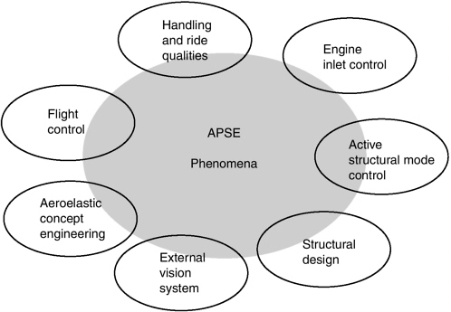
FIGURE 5-2 APSE effects interact with many other issues and design activities.
effects. The next step will be to develop techniques to incorporate this newly discovered fundamental knowledge into an appropriate (and perhaps quite different) multidisciplinary design methodology.
The committee noted that development of guidance and control systems is organizationally separate from the development of control laws; the former is in the flight deck organization, and the latter is in the aerodynamic performance organization. The committee could not ascertain why these groups, which have very closely related technical responsibilities, are not in the same organization. The organizational distance between the groups increases the possibility of miscommunication and unclear delineation of responsibilities.
Finding 5-1. An HSCT similar to the TCA will experience complex dynamic interactions involving the pilot and the APSE system, which includes the airframe (e.g., aerodynamic effects and elastic properties of the airframe structure), the propulsion system, and the flight control system (including the XVS). It is not yet clear how to design an HSCT that overcomes these effects and provides safe flying and handling qualities. Furthermore, the current HSR Program does not adequately address this problem.
Finding 5-2. The impact of APSE effects on flight dynamics and handling qualities may require changes in the aerodynamic and/or structural design of the TCA that would significantly reduce aerodynamic efficiency and/or increase structural weight, thereby reducing maximum range.
Finding 5-3. It is unlikely that the technical risk associated with APSE effects can be adequately addressed without building and flight testing an aircraft like the FAST (full-scale advanced supersonic technology) demonstrator.
Recommendation 5-1. The development of design tools and techniques for synthesizing and validating a highly integrated flight and propulsion control system and for properly addressing APSE effects on flight control and flight management systems should be established as a top-level research issue within the HSR Program during Phase II and the subsequent phases proposed by the committee. How to address APSE effects early in the aircraft-design cycle, before detailed structural models are developed, requires special attention.
Recommendation 5-2. The HSR Program should reevaluate the current TCA configuration in light of APSE effects. Because structural mode control will almost surely be required to achieve adequate flight dynamics and handling qualities, the optimum vehicle configuration may include additional and/or nontraditional aerodynamic surfaces. If necessary, such "control-configured" concepts should be included in future evaluations of aircraft design configurations.
Recommendation 5-3. An interdisciplinary team should be formed to fully address relevant aspects of the APSE problem, and the organizational distance between the groups responsible for (1) guidance and control systems and (2) control laws should be reduced or eliminated.
FLIGHT DECK SYSTEMS
Background
Aerodynamic considerations require that supersonic transports have a long nose that extends in front of the flight deck. This nose partly obscures the flight crew's forward vision. This is a significant problem during approach and landing because the flight crew cannot see the runway. Concorde supersonic transports have a moveable front section (i.e., a "droop nose") that is lowered during approach and landing to solve this problem (see Figure 5-3). This solution, however, adds significant weight and mechanical complexity to the aircraft design. The HSR Program intends to avoid these penalties by developing an XVS for the flight deck. The XVS would consist of external video and radar sensors, digital terrain databases, and displays mounted on the front bulkhead and instrument panels. The system would provide the flight crew with "synthetic vision" equal to or better than the unaided human eye through all phases of flight, including approach, landing, and ground operations. Like the flight deck systems on other large commercial transports, HSCT flight deck systems will be highly reliable and multiply redundant.
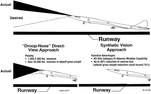
FIGURE 5-3 Droop nose versus synthetic vision for approach and landing. Source: NASA.
Flight Deck Displays
Two areas of the flight deck will display information to the flight crew: the forward bulkhead, which will be used in lieu of the front windows, and the front instrument panel. The front instrument panel will contain a series of displays similar to those found on today's newest subsonic aircraft, (e.g., the B-777 or A-340). Because this type of display is already in service, it poses minimal risk. The HSR design concept for the bulkhead displays uses a projection system (see Figure 5-4). Bulkhead displays have never been used on a commercial aircraft, and manufacturing a suitable projection display system will require technology that does not yet exist. Both types of displays are discussed in detail in the following sections.
Panel Mounted Displays
The HSR Program has selected active matrix liquid crystal displays (AMLCDs) as the baseline concept for the front instrument panel. AMLCDs are included in the designs of every new commercial and military aircraft, both fixed and rotary wing. In addition, a new display technology (field emission displays) may be mature by 2002 (Marticello and Hopper, 1996) and could be included by industry in the design of a commercial HSCT.
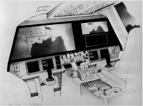
FIGURE 5-4 Artist's concept of one possible flight deck. Source: Boeing.
Because the HSCT flight deck will have a solid forward bulkhead instead of windows, the levels of sunlight will be somewhat reduced compared to conventional aircraft. As a result, HSCT flight deck displays will probably have reduced luminance requirements. Luminance requirements will be further reduced if the HSR Program succeeds in its effort to develop side windows that will darken automatically as a function of ambient light.
Bulkhead Displays
There are two alternatives for the design of the bulkhead display: (1) projection or (2) a "video wall" consisting of multiple panel-type displays (such as AMLCDs). Both alternatives are expected to be viable by 2002 (Hopper, Blanton, and Marticello, 1995). The HSR Program currently favors a projection system because of its potential to overlap the scenes from individual projectors, thereby creating a single, continuous, wide field-of-view image. A video wall of AMLCDs, on the other hand, would have visible seams between each AMLCD in the wall.
Display Resolution Requirements
HSCTs must provide a level of safety and performance that is equal to or better than other commercial transport aircraft in order to meet certification requirements and win the trust of airlines and airline passengers. This means the resolution of XVS displays must be comparable to the human eye. That is, the detail depicted by the XVS displays must enable the flight crew to see other aircraft and airfield features just as well (or better) than they could by looking through the windows of a conventional flight deck.
The resolution limit of the eye is 0.5 minutes of arc (Gille et al., 1994). However, empirical research within the HSR Program has determined that a resolution of 1 arc minute should be sufficient for visual tasks associated with the flight deck. Therefore, the XVS must have picture elements (pixels) that are no more than 1 minute of arc in size (as viewed by the flight crew), or 60 pixels per degree. Based on the field of view required by the TCA flight deck design, a minimum of about 7 million pixels will be required for the bulkhead displays.
The highest-resolution high-definition television (HDTV) requirement is 1,920 horizontal lines of video by 1,280 pixels per line, which corresponds to a total of about 2.1 million pixels (FCC, 1995). Four such displays would provide more than the 7 million pixels required for the XVS. In fact, the XVS concept currently under development by the flight deck contractor (Honeywell) fuses the output of four HDTV-quality cameras with four projectors into a tiled mosaic projection. If either the cameras or the projectors cannot provide the expected resolution, additional cameras and/or projectors will be required. This would increase system complexity and make it harder to create a single display image
without unacceptable variations in brightness or discontinuities between the scenes created by individual projectors.
As an alternate approach for achieving HDTV-level resolution, the XVS could employ digital micromirror devices, which are under development by Texas Instruments. These devices use millions of micromirrors as the image-producing "engine" in the projector—one micromirror for each pixel. By 2002, advances in micromirror technology may enable construction of an XVS bulkhead display by combining four devices for each bulkhead display (just as four projectors would be combined to create a single bulkhead display large enough to meet the requirements of the HSR Program).
No full-scale, flight testable XVS system will be built as part of the HSR Program; Honeywell is demonstrating component feasibility only. A full resolution system (60 pixels per degree) will be simulated during ground tests at Langley Research Center. The HSR Program will also conduct flight tests of XVS technology using the Air Force's Total Inflight Simulator (TIFS) aircraft. These flight tests will use the highest resolution displays that can be obtained at a reasonable cost (i.e., commercially available displays). However, these displays will not offer the full resolution required for an operational HSCT system. As a result, the display configuration on the TIFS will require more than four projectors, which could make it more difficult to create a single, consistent display image.
Flight Deck Program Challenges
The XVS will have the potential to help make the HSCT safer than current or future subsonic aircraft by creating visual meteorological conditions for the flight crew regardless of actual weather conditions. In order to achieve this goal, the XVS and other flight deck systems must, at a minimum, enable the flight crew to accomplish three crucial functions: avoid collisions with other aircraft; land the aircraft (even in adverse weather); and perform ground operations (e.g., taxi and position the aircraft at the gate).
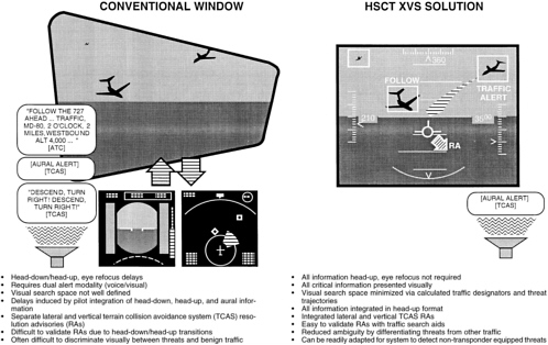
Aircraft Avoidance
Three key components of the XVS will help the flight crew avoid collisions with other aircraft (see Figure 5-5):
-
video cameras—high resolution cameras for takeoff, approach, and landing; and low resolution cameras for cruise
-
Traffic Collision and Alerting System, which is currently available on subsonic aircraft
-
X-band weather and windshear radar modified to detect noncooperative targets (i.e., aircraft not equipped with transponders) as small as a Cessna 150
As part of the HSR Program, a combined NASA-industry team headed by Langley Research Center has already flown variations of the X-band radar, and it plans to flight test an integrated system in 1999.
Studies by the HSR Program indicate that flight crew visual searches (with conventional windows) locate only 45 to 55 percent of other aircraft within terminal areas. The goal for the XVS is 99 percent; achieving this goal would constitute a significant safety improvement relative to conventionally equipped subsonic aircraft.
Ground Operations
Because the HSCT flight deck (and flight crew) is positioned so far forward of the nose gear (54 feet for the TCA design, compared to just 12 feet for the B-777), and because the HSCT flight crew will have no direct forward view, ground operations—such as taxiing—could pose a problem. The flight crew will not be able to see either the taxiway centerline or the taxiway itself during turns.
To investigate ground operations, the HSR Program is developing the Surface Operation Research and Evaluation Vehicle (SOREV) (see Figures 5-6 and 5-7).
The XVS on the SOREV will have bulkhead displays with a full field of view (as specified for the TCA). Like the TIFS, the SOREV XVS will use cameras, projectors, and displays with the highest resolution that is economically feasible (i.e., commercially available). Thus, the resolution of the SOREV XVS will probably be less than the goal of 60 pixels per degree. A lower resolution should be adequate for the SOREV, however, because ground tasks are less visually demanding than flight tasks. Construction of the SOREV is scheduled for completion during the summer of 1997. Initial testing will take place at a Boeing test facility in Seattle, Washington.
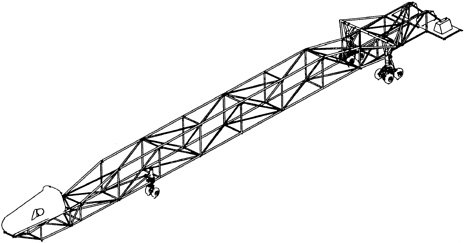
FIGURE 5-6 Surface Operation Research and Evaluation Vehicle (SOREV). Source: NASA.
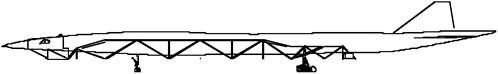
FIGURE 5-7 Comparison of the SOREV and TCA designs (side view). Source: NASA.
Adverse Weather Landing
Many aircraft landings have been made with limited or no external visibility. In the 1920s, Jimmy Doolittle made more than 100 landings with a hood to eliminate external visibility, and in 1929 he made a successful instrument landing in thick fog (Glines, 1989). Because of limited visibility through the cockpit windows, Charles Lindbergh used a periscope to land after his historic flight across the Atlantic Ocean. The Royal Air Force's Blind Landing Unit and the U.S. Air Force's All Weather Landing Program both have made numerous landings with severely restricted or no external visibility. All of these landings were made under very special circumstances (Lindbergh) or as part of research efforts designed to explore landing in poor visibility. There was no intention to develop a cockpit design that eliminated forward visibility during routine flight operations in clear weather. However, numerous landings have been made on blacked out runways at night by U.S. Air Force F-15E and F-16C aircraft using infrared images generated by the LANTIRN (landing, navigation and targeting-infrared, night) system.
The flight deck technology under development by the HSR Program is intended to enable HSCTs to land regardless of visibility. Under the worst visibility conditions (known as Category IIIc), the HSR Program anticipates that HSCT flight crews will monitor their aircraft while the on-board automatic landing system lands the aircraft. Subsonic transports already use similar systems, but the flight crew of an HSCT will have a visual image of the runway. In less severe conditions, the XVS is expected to allow flight crews to control their aircraft manually during approach and landing.
Redundancy and Graceful Degradation of the External Visibility System
The XVS will be the sole means of providing HSCT flight crews with forward visibility. Therefore, the XVS must be designed to operate reliably, with no catastrophic, total failures. (The level of reliability specified by the FAA for flight critical systems is 10-9: one failure per billion flight hours.) One way to achieve this level of reliability is to provide redundancy with multiple backup components and subsystems. For the XVS, these would include multiple cameras, software processors, and projectors. In addition, the displays would be independent for each member of the flight crew to ensure that a failure in the displays for one pilot would not affect the displays for the other pilot.
It is also critical that the XVS demonstrate graceful degradation so that failure
of an individual component or subsystem would have minimal impact on the overall operation of the aircraft. For example, suppose each bulkhead display had two projectors, one showing primary flight control symbology on the upper portion, the other displaying a navigation map on the lower portion. If the display projector for the top portion fails, the other projector should automatically shift function and display primary flight symbology instead of the navigation map, because the map is of lower priority. Validating that the XVS includes adequate redundancy and graceful degradation would be done during the HSCT design, development, test, and certification process.
Flight Deck System Conclusions
Almost all HSCT flight deck system technologies already exist or will be developed by industry and government programs other than the HSR Program. Even so, determining how to integrate these technologies into a system that can provide the required levels of performance and reliability is a formidable challenge. The HSR Program expects the flight deck development schedule (see Figure 5-8) to achieve its goals by 2002. The committee views this as an aggressive schedule and believes that the flight deck will remain a high risk area until flight testing validates technical feasibility.
Finding 5-4. Validating the performance of the XVS and other key flight deck technologies being developed by the HSR Program is crucial to the public acceptance and economic viability of an HSCT. Flight testing XVS technology using displays with lower resolution than the resolution needed for an operational HSCT increases the risk that test results will be unsatisfactory, which could reduce public acceptance of the XVS design concept.
Recommendation 5-4. To address flight deck system risk adequately, the preliminary flight tests planned during Phase II of the HSR Program should be supplemented by additional flight tests during the proposed technology maturation and advanced technology demonstration phases. These additional flight tests should use displays with resolution equal to the resolution needed for an operational HSCT.
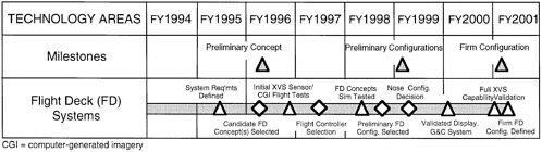
FIGURE 5-8 Flight deck system program schedule. Source: NASA.
COMMUNITY NOISE
Community noise refers to noise during takeoff and landing, not noise associated with sonic booms. Because the HSCT will operate subsonically over populated land masses, the major noise requirements being addressed by the HSR Program are associated with certification standards and community noise levels. Determining whether noise levels of a particular aircraft satisfy certification standards is based on three ground measurements: sideline noise (which is measured during takeoff at a specified point to the side of the runway); cutback noise (which is measured at a specified point under the aircraft after takeoff); and approach noise (which is measured at a specified point under the aircraft prior to landing).
Allowable levels of aircraft noise are defined in Federal Aviation Regulations (FARs); current levels are referred to as ''FAR 36 Stage 3.'' More restrictive noise requirements (a hypothetical and yet-to-be-defined "Stage 4") could be in place by the time an HSCT is ready for certification. Thus, the HSR Program is striving to meet and exceed Stage 3 noise goals.
All major U.S. airports have filed environmental impact statements for community noise. These statements are based on Stage 3 noise standards, but they are community specific because they define the ground area that is impacted by aircraft noise. Airports are required to file a revised impact statement if the size of this area increases by more than 17 percent. The HSR Program has established noise goals for the HSCT that will not exceed this threshold, based on a traffic analysis of five major airports and assuming a global fleet of 500 HSCTs. These noise goals are more restrictive than Stage 3 noise limits and are referred to as "Stage 3-X," where "X" represents the amount of additional reduction (in decibels) that is required in sideline, cutback, or approach noise. The HSR Program's current noise goals are Stage 3-1 for sideline noise, Stage 3-5 for cutback noise, and Stage 3-1 for approach noise. Cutback noise is currently the limiting condition driving noise-reduction efforts.
High-specific-thrust engines optimized for supersonic cruise have high jet velocities and are inherently noisy. Thus, unconventional designs for the engines and/or nozzles are required to meet the HSR Program's noise goals while providing acceptable subsonic and supersonic cruise performance. The HSR Program is using a multidisciplinary approach to meet these goals without exceeding the MTOW for an economically feasible design. This approach combines advanced engine cycles (such as a mixed flow turbofan) with a high thrust-to-weight ratio; advanced nozzle designs (mixer-ejector technology); advanced high lift devices (flaps); and specialized operational procedures (that allow engine power—and noise—to be reduced as soon as possible after takeoff).
The committee believes that the greatest risk associated with noise is not technical; it is the political risk that during the time it will take to develop an HSCT, noise standards will be lowered beyond the point that is feasible for an economically viable HSCT design.
Finding 5-5. HSCTs must be able to meet applicable regulatory noise standards. However, the HSR Program has established appropriate noise goals and is using an effective approach to achieve them.
CERTIFICATION
Certification is a critical issue for the HSR Program. Before making a product launch decision on any aircraft, industry must be confident that the FARs will permit timely certification of the aircraft design. For certification of an economically viable HSCT design, however, some regulations will need to be modified. This can be a lengthy process, especially in situations involving advanced technologies (such as those under development by the HSR Program) if additional data is needed to determine what certification standards are appropriate and how industry and the FAA can ensure that an aircraft design meets those standards. Thus, early action should be taken to understand and resolve certification issues associated with HSR technologies.
In January 1994, the FAA prepared a proposal for developing a long-range plan for certification of an HSCT. On September 13, 1995, NASA and the FAA signed a memorandum of agreement to formally initiate a cooperative program to address certification issues. The agreement states that the FAA will form a team of certification specialists to do the following:
-
Evaluate HSR Program technologies for safety, reliability, regulatory compliance, and economic impact relating to certification.
-
Work with NASA to plan research necessary to develop a certification basis for new and unique HSCT technologies.8
-
Develop a preliminary certification basis by 1998 and a final basis by 2001.
NASA agreed to do the following:
-
Provide the FAA with research data to support development of an HSCT certification basis.
-
Integrate key certification issues into the HSR Program.
-
Establish a certification issues program element in each of the key technical disciplines (viz., aerodynamics, structures and materials, flight deck, propulsion, and environmental impact).
As of April 1997, the FAA had established Certification Issues Coordination Teams (CICTs) for the flight deck, propulsion, structures, and noise/emissions (i.e., environmental impact); a fifth CICT for aerodynamics will be established
later. The CICTs are identifying specific certification issues related both to the designated system areas (e.g., flight controls and propulsion system) and to broader areas (e.g., safety, manufacturing, and operations). For example, the CICT for the flight deck is using ground simulators (at Langley Research Center, Ames Research Center, Boeing, and McDonnell Douglas) and the TIFS aircraft to examine HSCT certification criteria for collision avoidance, ground operations, manipulation of control surfaces during takeoffs,9 and other areas related to certification of an HSCT flight deck and the XVS. However, it is not clear how future activities by the CICTs will relate to other HSR Program activities.
Even when appropriate regulations are in place, the certification program for an advanced aircraft can be a lengthy and costly process, typically lasting five years for a subsonic commercial transport. Resolving critical technology issues is required to support timely approval of an HSCT certification basis and to avoid excessive delays during the HSCT certification program. This is especially important because of competitive pressures on manufacturers to shorten the aircraft design and development time and get products to market quickly.
Recommendation 5-5. The FAA and NASA (i.e., the HSR Program) should develop and periodically update a master certification plan that supports timely resolution of key HSCT certification issues and shows how the activities needed to resolve these issues are related to other HSR Program efforts.
AIRCRAFT OPERATIONS
The TCA design anticipates an HSCT that is significantly different from any subsonic aircraft because of its extended length (more than 80 feet longer than the largest subsonic aircraft currently in commercial operation), large delta wing, and high speed. Differences like these could have a significant impact on airline, airport, and air traffic control operations.
To be successful, the technologies developed by the HSR Program must be compatible with an HSCT design that is reasonably compatible with existing airline operating procedures, airport facilities (including taxiways), and air traffic control procedures. This does not mean that an HSCT should not require any modifications to current facilities, systems, or procedures. However, before an airline commits to purchasing HSCTs, and before a manufacturer agrees to build them, incompatibilities will need to be identified and evaluated. Industry has conducted several studies for this purpose. Although often anecdotal in nature, these studies have identified several areas of concern, including the following:
-
Deicing. Deicing fluids are used to remove snow and ice from the wings of aircraft prior to takeoff. Holdover time is the maximum allowable time between the completion of deicing and takeoff. Holdover times are reduced for large aircraft because there is more time for snow and/or ice to accumulate on portions of the aircraft that were deiced first. The TCA design configuration has a delta wing with about twice as much surface area as a large subsonic aircraft, such as a Boeing 777. It will take more time to deice HSCTs than subsonic aircraft, and new equipment or procedures may be needed to ensure holdover times are not reduced below operationally acceptable times.
-
Fueling. The HSCT will require four in-ground fuel pits per gate; subsonic transports require just one.
-
Airport gates. The HSCT will fit in a Boeing 747 gate when parked at an angle. However, 747 gates used for HSCT operations will probably require modifications for jet bridge positioning (in addition to the extra fuel pits), and these modifications may reduce the number of aircraft positions at some airports. Also, HSCT door sill heights, which are significantly higher than subsonic transports, will require modifications to existing jet bridges. However, there is ample precedent for airports to modify existing gates or to construct new gates to accommodate new classes of aircraft.
-
Taxi. The distance between the cockpit and nose gear (see the previous section on XVS ground operations) will probably require new taxi procedures. Also, depending on the taxi philosophy adopted, many taxiway turns may require fillets.
-
Air traffic control. The difference in cruise and climb speed between HSCTs and subsonic transports will require changes in current procedures and regulations.
Studies to date do not indicate that conceptual changes in the TCA design are required to meet operational needs of airlines, airports, or the air traffic control system. However, the committee believes that additional studies are needed to assess potential incompatibilities accurately, and the time, cost, and impact of corrective action. These studies should include dialogues with airlines, airport operators, and air traffic controllers to develop cost-effective, community-acceptable solutions. These solutions may not impact the TCA/TCn design, but they are likely to improve the prospects for early acceptance of HSCTs by airlines, airport operators, and air traffic controllers.
Lessons learned from operating experience with the Concorde will provide some useful information for addressing HSCT compatibility issues. However, an HSCT will be quite different from the Concorde in terms of design, the size of the expected fleet (500 for an HSCT, whereas only 13 Concorde aircraft remain in commercial service), and environmental requirements (the Concorde is exempt from community noise standards, and NOx engine emissions are four times higher
than the goal for the HSCT). Thus, solutions used for the Concorde will not necessarily apply to an HSCT.
Finding 5-6. The design and operating characteristics of an HSCT will require some changes in airline, airport, and air traffic control system facilities and procedures. However, making changes to airport facilities (including taxiways) and air traffic control procedures, although technologically simple, may be difficult from a funding and environmental/community acceptance perspective. Failure to anticipate problems and make required changes could reduce HSCT market demand below current estimates.
Recommendation 5-6. During the recommended advanced technology demonstration phase, industry and the HSR Program should identify and evaluate changes in airline, airport, and air traffic control system facilities and procedures that may be required to accommodate an HSCT. In particular, industry should conduct a detailed study of infrastructure issues at key airports worldwide that an HSCT is expected to service. As a first step, these issues should be included in the recommended effort to validate HSCT market size (see Chapter 2).
REFERENCES
Coleman, E.E. 1996. Personal communication from Edward E. Coleman to Dr. David K. Schmidt, December 20, 1996.
FCC (Federal Communications Commission). 1995. Advisory Committee on Advanced Television Service. Final Technical Report, October 31, 1995. Washington, D.C.: Federal Communications Commission.
Gille, J., R. Samadani, P. Martin, and J. Larimer. 1994. Grayscale/Resolution Tradeoff. Pp. 47–59 in Proceedings, Society of Photo-Optical Instrumentation Engineers (SPIE) Conference: Human Vision, Visual Processing, and Digital Display V, held February 8–10, 1994, in San Jose, California. Bellingham, Washington: Society of Photo-Optical Instrumentation Engineers.
Glines, C.V. 1989. Flying Blind. Air Force Magazine. Vol (Sept.): 138–141.
Hopper, D.G., R.B. Blanton, and D.N. Marticello. 1995. Large Area High Definition Cockpit Displays. Journal of the Society of Photo-Optical Instrumentation Engineers. 2462: 184–197.
Marticello, D.N., and D.G. Hopper. 1996. Insertion of Field Emission Displays into High Performance Cockpits. Journal of the Society of Photo-Optical Instrumentation Engineers. 2734: 32–36.
Shelton, D.R., and O.C. Harris. 1994. The Effect of Inlet Unstart on Flight Control and Passenger Discomfort for a High Speed Civil Transport Aircraft. NASA Contractor Report 195318. Los Angeles, California, Lockheed Aeronautical Systems Company.
Waszak M.R., J.B. Davidson, and D. K. Schmidt. 1987. A Simulation Study of the Flight Dynamics of Elastic Aircraft. NASA Contractor Report NAG1254. Washington D.C.: National Aeronautics and Space Administration.


