
Analysis of Interactions Between Nonlinear Waves and Bodies by Domain Decomposition
G.-X.Wu, Q.-W.Ma (University College London, United Kingdom), R.Taylor (University of Oxford, United Kingdom)
ABSTRACT
The paper extends to the three dimensions a previously described two dimensional finite element analysis of non-linear water waves interacting with bodies. The domain decomposition method is used to divide the computational domain into manageable regions, in each of which the computation is performed independently of the other regions. Results are given for standing waves in a rectangular container; waves generated by a wave maker in a rectangular tank; and the interaction between such waves and a vertical cylinder.
INTRODUCTION
Many problems in naval hydrodynamics are fully non-linear. Well known examples include motions in rough seas, slamming, ship capsize etc. The fully non-linear theory is usually solved by a time marching method. This assumes that the wave profile and the position of the structure are known at a particular instant. The problem can then be solved by numerical techniques. The Bernoulli equation enables us to find the force on the structure. If the structure is not fixed, Newton's law will give the new acceleration. The acceleration then gives a new velocity which further gives the new position of the structure. Similarly, the velocity obtained on the free surface will give a new free surface profile. All these will enable the problem to be solved at the next time step. The procedure can be repeated for any desired number of time steps.
The solution of the velocity potential at each time step can be obtained by various numerical methods. The three dimensional boundary element method has been adopted in many publications (Liu & Yang [9], Zhou & Gu [10], Broeze & Zanbergen [11], Xu & Yue [12], Ferrant [13]). In this paper we shall adopt the finite element method. The method has been recently applied to the two dimensional problem by Wu & Eatock Taylor [5]. It has several distinct features. When triangular elements are used together with linear shape functions, the global matrix can be calculated explicitly. All it requires is the areas of the elements. This reduces CPU time dramatically. Also the global matrix is banded and symmetric. Experience with the two dimensional problem shows that in many cases the memory required by the finite element method is not much more or even far less than that required by the boundary element method which corresponds to a fully populated matrix. Our preliminary investigation suggests that the finite element method does have several advantages.
One of the difficulties in this problem is the radiation condition. Unlike the fully linearised problem, no explicit equation has been established for the condition when the problem is non-linear. In numerical calculation, various schemes have been proposed (e.g. [ 1], [4]). They
can absorb waves efficiently in some cases, but are not always effective in general. Even when they are effective, they have to be placed sufficiently far away from the body. This means that the computational domain is usually big, which will require a large number of elements. On the other hand, when the required memory exceeds the physical memory of the computer, only a small percentage of CPU will be used. This makes the calculation extremely inefficient. Wu and Eatock Taylor [5] therefore adopted domain decomposition. The required memory will then depend on the sizes of the subdomains which can always be subdivided if necessary. The continuity across the subdomain is achieved through iteration.
In this work, we shall use the three dimensional finite element method to consider the problem of a vertical cylinder in a wave tank. The methodology is first verified using the analytical solution for a two dimensional wave maker. The case may seem simple enough, but it is found that care is needed in dealing with cross waves. The computer code is also verified by the linearized analytical solution for three dimensional standing waves. The relative merits of various domain decomposition schemes are discussed. Results for the vertical cylinders in the tank are provided.
MATHEMATICAL FORMULATION AND NUMERICAL TECHNIQUE
We consider the problem of a vertical cylinder in a wave tank as shown in figure 1. (x,y,z) denotes a Cartesian co-ordinate system with x axis pointing in the longitudinal direction of the tank and z upwards. The origin of the
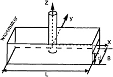
Fig. 1 The layout of the wave tank
system is located on the mean position of the free surface and the centre of the cylinder. B, L and d in the figure indicate the width, length and depth of the tank, respectively.
Based on the usual assumptions of ideal flow, the velocity potential ![]() satisfies Laplace's equation:
satisfies Laplace's equation:
![]() 2
2![]() =0 (1)
=0 (1)
in the fluid domain Ω. The condition on the piston wave maker can be written as
(2)
where U(t) is the velocity of the wave maker. On the fixed boundary the condition is:
(3)
where n is the normal of the surface pointing out of the fluid domain. On the free surface z=η(x,y,t), the kinematic and dynamic conditions can be written as
(4)
(5)
where g is the gravitational acceleration. These are then combined with the initial conditions which usually assume that the wave elevation and the potential on the free surface are zero.
When the wave generated by the wavemaker encounters the cylinder, it will be diffracted. The reflected wave will travel back towards the wave maker. The transmitted wave, on the other hand, will propagate towards the other end of the tank. As the time step increases, the waves reflected by the wavemaker and the far end of the tank will arrive at the cylinder. This will distort the wave loading on the cylinder. Several approaches have been proposed to absorb the reflected wave (e.g. [1]) and the transmitted wave (e.g. [4]). They are effective in some cases but they all have their limitations. Here we do not intend to investigate the effectiveness of various wave absorption schemes at the far end. Instead we simply use a relatively long tank and the computation is
terminated before the reflection at the far end has significant effects on the desired results.
At each time step, the above problem can be solved by a finite element method. The fluid domain will be discretised using finite elements and the velocity potential written in terms of the shape function Nj(x, y, z):
(6)
where N is total number of nodes and ![]() j are the values of the potential at the nodes. Using the Galerkin method and Green's second identity, we have
j are the values of the potential at the nodes. Using the Galerkin method and Green's second identity, we have
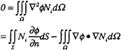
(7)
where S is the boundary surface of fluid domain. When the boundary conditions are imposed and equation (6) is used, equation (7) becomes
(8)
where Sf is the free surface and Sm is the wetted surface of the wave maker. If linear shape functions are used as in this paper, the integration in equation (8) can be obtained from the volumes of the elements. Once the solution is found, the force can be calculated using an equation similar to that in the paper of Wu & Ma [6].
DOMAIN DECOMPOSITION TECHNIQUE
It has been noted in the work of Wu & Eatock Taylor (5) on a two dimensional body, that the finite element method has some advantages over the boundary element method in terms of both CPU and memory requirement. The reason is that although the finite element method discretises the fluid domain rather than the boundary alone, the nodes influence each other only when they are physically connected. As a result, the matrix is banded. In the boundary element method, on the other hand, each node will influence all other nodes through the Green function. This leads to a full matrix. Furthermore, the influence coefficients in the finite element method can be obtained from the volumes of the elements when linear shape functions are used, while in the boundary element method they are calculated from logarithmic and triangular functions, which requires more CPU.
The finite element method has been applied with some success in the two dimensional problem. For the three dimensional problem, however, the computational domain is increased dramatically. One hundred divisions in each direction will lead to over one million nodes. This is not helped by lack of a suitable radiation condition. The memory requirement is therefore usually beyond the limit of most computers. We therefore make use of the domain decomposition.
The domain decomposition technique has been used in many cases (see for example Glowinski et al. [2]). Wu & Eatock Taylor [5] have also adopted this method for the two-dimensional non-linear water wave problem. The essence of this technique is that it divides the computational domain into several subdomains, which may overlap. The computation is then performed in each subdomain. The continuity at the interface of the subdomains is achieved by iteration.
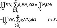
We consider an example shown in Fig.2a in which two subdomains are used.
Fig. 2 Illustration of domain decomposition
γ12 in the figure is the interface of the two subdomains Ω1 and Ω2, on which the following continuity conditions are imposed
(9)
where ![]() 1 and
1 and ![]() 2 are the potentials in the corresponding subdomains. The problem is then solved in each subdomain and the continuity is achieved by the following iteration scheme
2 are the potentials in the corresponding subdomains. The problem is then solved in each subdomain and the continuity is achieved by the following iteration scheme
(10)
where
(11)
and λ(0) can be taken from the normal derivative at the previous time step. It can be shown that if ρ is properly chosen the iteration will converge [2].
The case in Fig.2b is similar to that in Fig. 2a, but there is an overlap between the two subdomains. Their common part is Ω12. γ12 is the interface between Ω2 and Ω12; γ21 is the interface between Ω1 and Ω12. Continuity is achieved by imposing the following condition
![]() 1=
1=![]() 2 in Ω12 (12)
2 in Ω12 (12)
which can be found to be equivalent to:
![]() 1=
1=![]() 2 on γ12 and γ21 (13)
2 on γ12 and γ21 (13)
as these functions satisfy the Laplace equation.
The solution starts by assuming ![]() 1 on γ12 to be known. This allows us to find
1 on γ12 to be known. This allows us to find ![]() 1 which gives its value on γ21 for
1 which gives its value on γ21 for ![]() 2. The solution in Ω2 can then be obtained which in turn gives a new boundary condition for
2. The solution in Ω2 can then be obtained which in turn gives a new boundary condition for ![]() 1. This can be written as
1. This can be written as
(14)
(15)
where µ is the relaxation coefficient and
(16)
The initial condition is again taken from the solution at the previous time step.
RESULTS AND DISCUSSION
In the analysis below, the various parameters are nondimenionalized by redefining them as follows:
![]() → d(gd)1/2
→ d(gd)1/2![]() (x,y) → d(x,y)
(x,y) → d(x,y)
t → (d/g)1/2t ω → (g/d)1/2ω
where ω is a frequency.
The fluid domain is divided into many small hexahedra. Each hexahedron is then divided into six tetrahedra. A typical example is shown in Fig.3.
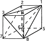
Fig 3. Division of hexahedron
We first consider the problem of a wave maker which starts moving suddenly. The length of the tank is L=5d and the width is d/2. The fluid domain is discretised by J+1 transverse planes, M+1 longitudinal planes and N+1 horizontal planes. This forms JMN hexahedra and 6JMN tetrahedra. The number of nodes is equal to (J+1)*(M+1)*(N+1). Cosine spacing is used in the x direction and the z-coordinate of each node is determined from an exponential distribution as used by Wu and Eatock Taylor [5].
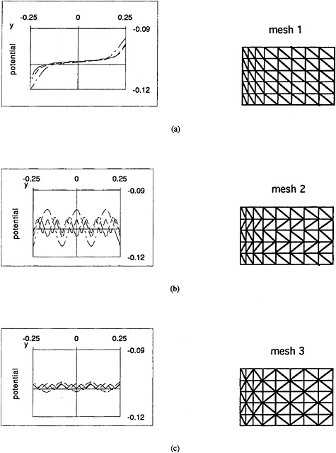
Physically, this problem is two-dimensional. The potential is not a function of y. In our analysis, however, it is found that the variation of the potential with y greatly depends on the mesh structure. Fig.4 gives the velocity potentials at z=–.0375 on the wave maker obtained from different meshes. It shows that the variation of the potential with y decreases and the results tend to the analytical solution [8] when the number of elements increases, but the rate is quite slow. The difficulty here is that any error will cause a bigger error at the next time step. Before long, the accumulated error will cause instability. One way to solve this problem is to use a sufficient number of elements, but this would not be economical. Here we use the mesh in Fig.4c which has the least variation and combine this with a 5-point smoothing scheme [3] in the y direction. Fig.5 gives the results after this treatment. Fig.5a shows that there is no variation visible. Indeed it is found that the results are identical up to the fifth figure after the decimal point. They are also found to be in good agreement with the analytical solution [8]. Fig.5(b,c) give the results for the potential and the vertical velocity on the wave maker. They are in good agreement with the analytical solution.
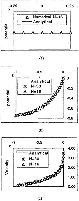
Fig 5 The potential and vertical velocity on the wave maker at t=0+ for the sudden motion with U=1.0(mesh generated with J=60, M=6 and different N)
We next consider the problem of the wave maker undergoing the following oscillatory motion:
U(t)=aωsin(ωt) (20)
where a is the nondimensionalised amplitude. The length of the tank is taken as L=20d and width B=d/2. The calculation is made with ω=1.5 and a=.016. In this analysis, the fluid domain is divided by J=200, M=6 and N =16. Fig.6 gives the wave elevation history on the wave maker and at the centre of the tank. Some typical wave profiles in the tank at times t=10,15, 20 and 25 are shown in Fig.7.
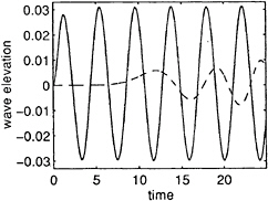
Fig 6. Wave elevation history (solid line: on the wave maker; dashed line: x=0)
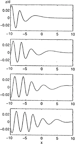
Fig 7 Wave profiles at different time steps
Next considered is the problem of a standing wave in a tank with L=B=d which is discretised by J=M=N=20. The initial free surface elevation is given as:
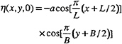
(21)
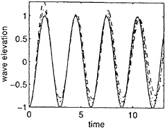
Fig 8 The standing wave elevation history at x=L/2, y=B/2 (——— analytical;
············ numerical for a=0.01;
—— —— numerical for a=0.05;
— — — numerical for a=.1)
and the potential on the free surface is zero. The linearised solution can be found as
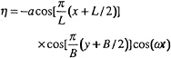
(22)
where
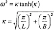
(23)
Fig.8 gives the wave elevation (divided by a) at x=L/2, y=B/2 a=0.01, a=0.05 and a=0.1 respectively. The results have been compared with the linear analytical solution. It can be seen that the results agree well with the analytical solution when the amplitude is small. As the amplitude increases, nonlinear effects become more important.
We now consider the case of a vertical cylinder located at the centre of the tank as shown in Fig.1. The radius of the cylinder is R=0.05d. The length and width of the tank are taken as L=10.5d and B=d/2 (or L=210R and B=10R), respectively. We shall use the domain decomposition to solve this problem. Before that
we shall first investigate the effectiveness of this technique by considering the case of the wave maker which starts moving suddenly. It is found that the scheme used by Wu and Eatock Taylor [5] without overlapping is less efficient than the one with overlapping. The latter is therefore adopted. It has also been found that the efficiency very much depends on the relaxation coefficient µ and the sizes of the overlapping zones.
Several tests have been conducted to find a suitable value for µ. In the calculation the whole fluid domain is divided into five sudomains: one enclosing the cylinder and two on each side. The details are shown in Fig.9, in which Cij is the length of the overlapping zone. Fig.10 shows the number of iterations against µ with Cij=0.2d. It can be seen from the figure that µ=1.382 is a suitable choice.
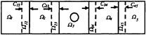
Fig 9 A typical configuration of subdomains
Further tests have been made for the sizes of the common domains (i.e. Cij). The total CPU depends on the number of iterations and the CPU required for each subdomain. A bigger overlapping zone usually leads to a smaller number of iterations, which will reduce CPU. On the other hand, a bigger overlapping zone will lead to bigger subdomains, which will increase CPU. A proper balance is therefore needed. Fig. 11 gives some preliminary results which were obtained by taking the relaxation coefficient as µ=1.382 and all Cij being the same. CPU for Cij=0.1d in the figure is taken as unity. It is seen that Cij=0.2d leads to least CPU.
It should be pointed out that the optimised values mentioned above may depend on other parameters such as the sizes of elements, the wave length and the number of the subdomains etc. Further investigation is needed to achieve a better understanding of the dependence of CPU on relaxation coefficient and the length of the overlapping zone.
We now give the results for the cylinder in the wave tank. The subdomains used are similar to those shown in Fig.9. The motion of the wave maker is similar to that given in equation (20) but
ω=2.0 a=.008
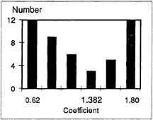
Fig. 10 The number of iterations against relaxation coefficients
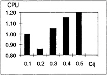
Fig. 11 CPU against Cij
Fig. 12 gives wave runup on the surface of the cylinder at t=15, 20 and 25, where θ representes the angle measured from x-axis. Fig 13 provides the horizontal force acting on the cylinder which has been nondimensionalsed by ρgR2a, (ρ is the density of water). The total number of elements used in this case is 203,520. The calculation takes about 193 hour CPU on a DECalpha 400 workstation for 1,000 time steps. Due to this extensive CPU demand, no systematical investigations using finer mesh and smaller time steps have been taken regarding the accuracy of the results shown. Further work is clearly needed.
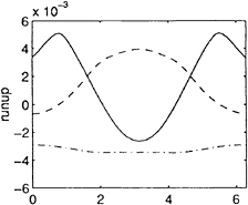
Fig 12 Runup on surface of the cylinder (— · — · — t=15; — — — t=20; ———— t=25)
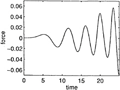
Fig 13 Horizontal force acting on cylinder
CONCLUSIONS
This paper has shown how the domain decomposition method may be extended to a three-dimensional finite element analysis of non-linear water waves interacting with bodies. A scheme of overlapping adjacent domains is found to be more effective than an earlier scheme used by the authors for the two-dimensional problem, and a study has been conducted into the optimum amount of overlap and the optimum relaxation coefficient in the iterative scheme. Preliminary results have been obtained for the case of a vertical cylinder in a wave tank. The method requires extensive computer run times when implemented on a workstation, and further work is required to improve the methodology. This includes the development of a procedure for combining the domain decomposition method with wave absorbing techniques to allow the imposition of appropriate radiation conditions close to the body.
The results shown are for the case of a fixed cylinder. For a floating structure, body motions need to be taken into account, and it is intended to achieve this by using the method described by Wu and Eatock Taylor [7].
ACKNOWLEDGEMENT
This work forms part of the research programme “Uncertainties in Loads on Offshore Structures” sponsored by EPSRC through MTD Ltd and jointly funded with: Amoco (UK) Exploration Company, BP Exploration Operating Co Ltd, Brown & Root, Exxon Production Research Company, Health and Safety Executive, Norwegian Contractors a.s., Shell UK Exploration and Production, Den Norske Stats Oljeselskap a.s., Texaco Britain Ltd.
REFERENCES
1. Cointe, R., Geyer, P., King, B., Molin, B. and Tanoni, M., 1990, “Nonlinear and linear motions of a rectangle barge in a perfect fluid, ” 18th Symp. on naval hydrody., Univ. of Michigan, Ann Arbor, pp. 85–98.
2. Glowinski, R., Dinh, Q.V. & Periaux, J., 1984, “Domain decomposition for elliptic problems”, in Finite Element Methods, John Wiley and Sons, Chichester, Vol. 5, pp. 45–106.
3. Longuet-Higgins, M.S. & Cokelet, E.D., 1976, “The deformation of steep surface waves on water: I. a numerical method of computation” , Proc. R. Soc. London, A Vol. 350, pp.1–26.
4. Romate, J.E., 1992, “Absorbing boundary conditions for free surface waves”, J. Comp. Physics. Vol. 99, pp. 135–145.
5. Wu, G.X. and Eatock Taylor, R., 1995, “Time stepping solutions of the two dimensional
non-linear wave radiation problem,” Ocean Engng, Vol. 22, No. 8, pp 785–798.
6. Wu, G.X. & Ma, Q.W., 1995, “Finite element analysis of nonlinear interactions transient waves with a cylinder”, OMAE'95, Vol. 1, part A, pp329–339.
7. Wu, G.X. & Eatock Taylor, R., 1996, “Transient motion of a floating body in steep waves”, 11th international Workshop on Water Waves and Floating Bodies, Hamburg, Germany.
8. Peregrine, D.H., 1972, “Flow due to vertical plate moving in a channel”, unpublished note, Department of Mathematics, University of Bristol.
9. Liu, Y.Z. and Yang, C, 1987, “Nonlinear radiation of an axisymmetric cylinder,” Adv. in Hydrodynamics ( China), Vol. 2
10. Zhou, Z. and Gu, M., 1990, “A numerical research of nonlinear body-wave interaction, Proc. 18th Symp. on Naval Hydrodynamics, Ann Arbor, Michigan, pp.103– 117.
11. Broeze, L and Zandbergen, P.J., 1992, “The development of a three-dimensional panel method for nonlinear free surface waves,” 7th Intl. Workshop on Water Waves and Folating Bodies, Val de Reuil, France.
12. Xu, H and Yue, D.K.P, 1992, “Numerical study of three-dimensional overturning water waves,” 7th Intl. Workshop on Water Waves and Folating Bodies, Val de Reuil, France.
13. Ferrant, P., 1994, “Radiation and diffraction of nonlinear waves in three dimensions, ” BOSS, MIT, pp.507–524.


