
4
Potential Surfactant Additives: The Search for the Oxymoron
Paul Becher
Paul Becher Associates Ltd.
According to the program, I am expected to discuss potential surfactant additives. This is a difficult problem, because prior to hearing the talks at this meeting, it was impossible to determine what these additives were, in fact, to be added to. I may say that this problem has not become much easier, but I shall return to that point a little later.
Let me concentrate instead on the subtitle of my presentation, namely, ''The Search for the Oxymoron." Since this is an educated audience, I will assume that everyone knows what an oxymoron is. However, on the statistically small chance that some member of the audience has not come across this word, I give you the following definition (American Heritage Dictionary, 1996):
ox·y·mo·ron (![]() ) n., pl.ox·y·mo·ra (
) n., pl.ox·y·mo·ra (![]() ) or ox·y·mo·rons. A rhetorical figure in which incongruous or contradictory terms are combined, as in a deafening silence and a mournful optimist. [Greek
) or ox·y·mo·rons. A rhetorical figure in which incongruous or contradictory terms are combined, as in a deafening silence and a mournful optimist. [Greek ![]() , from neuter of
, from neuter of ![]() , pointedly foolish: oxus, sharp; see OXYGEN +
, pointedly foolish: oxus, sharp; see OXYGEN + ![]() , foolish, dull.] —ox´y·mo·ron 'ic (
, foolish, dull.] —ox´y·mo·ron 'ic (![]() ) adj.—ox´y·mo·ron'i·cal·ly adv.
) adj.—ox´y·mo·ron'i·cal·ly adv.
However, the oxymoron for which we are searching is (as you might guess) "nonflammable fuel." You will at once assure me that what we are seeking is actually "reduced flammability," and I will agree. But the further target is, at least, worth thinking about.
The oxymoron in question is not particularly new. I recall using it in, I believe, 1945. At that time, I was serving as an enlisted research chemist in the Air Force laboratories at Wright Field, Dayton, Ohio. My general area of activity was work on petroleum products used in military aircraft, including fuels, lubricants, and hydraulic fluids. A principal target was the development of a nonflammable hydraulic fluid.
We did, in fact, succeed in developing a usable fluid, and I share in a patent (U.S. Patent 2,470,792) which, to the best of my knowledge, has never actually been tested, much less used, by the Air Force (or for that matter, anyone else). I am not too unhappy about this result because I have since developed some doubts about the toxicity of the principal ingredient. Nonetheless, I may perhaps be able to claim priority in this area over most attendees to this workshop. I should point out that even in 1945 we recognized that the term nonflammable fuel was an oxymoron. However, we also understood that it was, in principle, obtainable and, perhaps, important.
While teaching in the Georgia University system, I did a small amount of research into the synthesis of the principal ingredient of our patented hydraulic fluid. This resulted in my one and only citation in the Beilstein Handbook of Organic Chemistry. However, subsequent employment by the Colgate-Palmolive Company and the Atlas Powder Company, which I followed through its various name changes finally to ICI Americas, shifted my interest to surface-active materials. So I allowed this particular oxymoron to fall into disuse.
Although my research interests have changed, my fate seems to be involved in this problem. About 20 years ago, I was invited to participate in a study by a Bureau of Ships committee to consider the problem of the flammability of hydraulic fluids in submarines. Flammability, as anyone who has ever been inside a submarine knows, is an even greater hazard in a submarine than in aircraft. Nowhere in a submarine is one more than a few feet from a hydraulic line. In addition, one has the option of parachuting from an airplane, but the same option does not present itself in a submerged vessel. The committee met here in Washington, D.C. to consider the problem. Although the Navy's not unreasonable lack of interest in retrofitting the entire submarine fleet limited our options rather severely, a report was issued. As far as I know, none of the recommendations was ever implemented.
My final experience with this problem actually completed my tour of the military services, as well as resurrecting, at last, the oxymoron. I was called to join a committee at the U.S. Army Fuels & Lubricants Laboratory in San Antonio, Texas, to consider problems involving fuel fires in military vehicles. This is a substantial problem because many military vehicles, tanks and the Bradley vehicle, for example, are run by diesel engines where the fuel doubles as engine coolant. Thus, at any time there may be as many as 400 gallons of diesel fuel sloshing about the vehicle.
The Army also proved to be unwilling to retrofit, and other restrictions seriously reduced the possible solutions to the problem. Nonetheless, a report was issued. To the best of my knowledge, the recommendations for further study were not implemented.
It will be noted that I have qualified the results of my tour of the services by saying in each case, "to the best of my knowledge" or "as far as I know." The reason for the qualification is obviously the possibility of "military secrecy" (another oxymoron?). The fact that we are here today suggests, however, that no great measure of success has been achieved in the intervening years.
Now, to return to my principal theme: in what way can surface-active agents, new or old, contribute to progress in this area? The obvious answer is as stabilizers in multiphase systems. Some form of emulsion seems an obvious approach. The limitation that no water be included in the formulation has been imposed. It should be noted that hydrocarbon-water systems have been used extensively as fuels, notably in diesel engines. Generally, these have been water-in-oil systems and have been investigated with a view to reducing emissions and costs, rather than to reducing flammability. An interesting review of some research in this area was recently given by Thompson (Thompson, 1990). In addition, some work has been done on using oil-in-water emulsions as heating or power-plant fuel, namely using emulsions of heavy crude, as exemplified by Orimulsion fuel (Briceno et al., 1990; Marcano et al., 1991).
These studies reveal that fuel emulsions can indeed burn. Unfortunately, I have not been able to determine if studies on the prevention or limitation of burning have been carried out. I have identified a suggestive paper by Kitamura and coworkers dealing with water-in-oil emulsions (Kitamura et al, 1991). This paper suggests that the flash point decreases with increasing surface area per unit volume of the emulsion. Since the utility of the emulsion as a fuel depends on its ability to burn, it is obvious that this clue must be employed with some caution.
All of the papers I consulted in preparing this presentation on the use of surface-active agents have included very conventional surfactants in the formulations. This is not surprising because there are literally thousands of surface-active materials available to the investigator or formulator. The laws of thermodynamics being what they are, one may expect that all of these materials will act in pretty much the same way. For any given system, these thousands of surfactants may shrink to a few suitable ones. The methods of determining the appropriate ones are well known and are described in a number of places, including in my own work.
In conclusion, new approaches to this problem may be rather limited. Although it may be that no current product meets the needs of a new system subjected to, for example, environmental extremes, the synthesizer of new materials will be guided by the wealth of previous experience, as well as by the laws of thermodynamics.
REFERENCES
American Heritage Dictionary (3rd ed.). 1996. CD-ROM version.
Becher, P., and W. Schelsinger. 1949. U.S. Patent 2,470,792.
Becher, P. In press. Emulsions: Theory and Practice (3rd ed.). American Chemical Society (ACS) Monograph. Washington, D.C.: ACS.
Briceno, M.I., M.L. Chiroinos, I. Layrisse, G. Martinez, G. Nunez, A. Padron, L. Quintero, and H. Rivas. 1990. Emulsion technology for the production and handling of extra heavy crude oils and bitumens. Revista Tecnica Intevep 10(1):5-14.
Kitamura, Y., Q. Huang, Y. Oka, and A Williams. 1991. Flashing of superheated water-in-oil emulsions. Journal of Chemical Engineering of Japan 23:711–715.
Marcano, N., M. Pourkashanian, and A. Williams. 1991. The combustion of bitumen-in-water emulsions . Fuel 70(8):917–923.
Thompson, R.V. 1990. To fly to float: a half life of research and development. Transactions of the Institute of Marine Engineering 102(1):1–16.
5
Fire Safety in Military Aircraft Fuel Systems
Robert G. Clodfelter
AFP Associates Inc.
INTRODUCTION
Because of the large quantity and dispersed storage of fuel on board aircraft, there is a high probability that aircraft accidents will involve fire in one way or another. The probability of fire is increased by the aircraft design requirement for lightweight structures for fuel containment. Fire could result from a fuel explosion in a fuel tank, fuel leakage into dry bays, cabin areas, cargo bays, or engine compartments, or from a fuel release on impact. Whether the fire or explosion is caused by the initial event or by a secondary cause, the result is often catastrophic.
One way to reduce the aircraft fire problem is to develop a fuel that is less susceptible to combustion in locations other than the engine. This is a challenging technical and economic goal, especially considering the requirements of aircraft operation and fuel availability. Candidate "fire-safe" fuels should have the availability, reasonable cost, and suitable physical and chemical properties for direct utilization in operational aircraft without extensive fuel system modifications or serious degradation of aircraft performance. Because of these stringent requirements, most of the successful efforts to reduce the aircraft fire hazard have been improvement in prevention and protection areas rather than development of fire-safe fuel. This paper uses the term fire-safe in the broad sense, i.e., any change in fuel that improves fire safety.
The Air Force's recent conversion from JP-4 (which has Jet B as its commercial equivalent) to JP-8 fuel is a step in the right direction from the standpoint of fire safety. Army aircraft use the same fuel as the Air Force. The Navy has used JP-5 fuel for many years for fire safety reasons. Properties of these military fuels and commercial fuels (Jet A and Jet A-1) are given in Table 5-1. The production of these fuels is illustrated in Figure 5-1 as a percentage obtained by simple distillation of an average crude oil. By using refinery techniques, such as hydrocracking, hydrotreating, and reforming, these percentages can be adjusted on demand. However, fewer added refinery costs are associated with converting heavy bottom fuels to high vapor pressure fuels (low flash point temperature) than vice versa.
The use of JP-5 and JP-8 was implemented to reduce the availability of fuel vapors for ignition and to reduce the amount of fuel vapor which could support a reaction. The use of antistatic additives in aircraft fuels (a specification requirement for JP-4 and JP-8 but not for Jet A or Jet A-1) is helpful for minimizing static as a potential ignition source. The lack of an antistatic additive may have been a contributing factor in the recent TWA 800 accident (17 July 1996). Other
TABLE 5-1 Comparison of the Properties of Aviation Fuels
|
|
JP-4 |
JP-8 |
Jet A-1 |
Jet A |
JP-5 |
|
Minimum Flash Point, °F |
-20 |
100 |
100 |
100 |
100 |
|
Maximum Freeze Point, °F |
-72 |
-53 |
-53 |
-40 |
-51 |
|
Lbs/gal |
6.3 |
6.7 |
6.7 |
6.8 |
6.8 |
|
BTUs/gal |
118,900 |
124,500 |
124,500 |
125,700 |
126,000 |
|
Vapor Pressure, psi |
2-3 |
|
|
|
|
|
Viscosity, cSt@-4°F |
2.4 |
4.2 |
4.2 |
5.5 |
5.5 |
|
Acid NR, mg KOH/g |
0.015a |
0.015a |
0.1 |
0.1 |
0.015a |
|
a Allow up to 0.022. |
|||||
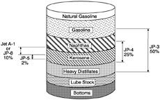
FIGURE 5-1 Availability of distillate fuels.
attempts to make fuels more fire safe have included developing modified fuels, such as gels, emulsions, and antimisting kerosene (AMK). Tests on modified fuels have demonstrated potential reductions in ignition and flame propagation by the mists and sprays normally associated with "neat" fuels in the event of a crash landing and structural failure. All of the currently known modified fuels, however, have serious operational and logistical problems mainly associated with fuel transfer, storage, and engine performance. Many of the proposed solutions for these problems have inherent negative safety factors and present new design challenges. Needless to say, modified fuels have only been used in test programs and not operational service.
The search for a less hazardous fuel has taken two fundamental approaches. The first entails reducing the availability of fuel vapors for ignition and limiting their availability for feeding the combustion process. This may be accomplished by increasing the flash point temperature of the fuel (lowering the vapor pressure), a fuel property that can be easily measured. Fuels with a wide range of flash point temperatures are currently available. Gasoline has a flash point temperature of about -60°F, whereas aviation jet fuels have flash points in the 100¹ to 150°F range (with the exception of JP-4 [Jet B] which has a flash point near 0°F). Unfortunately, increasing the flash point temperature of a fuel has negative operational and performance effects, such as increased viscosity, increased freeze point temperature, and problems with engine starting and engine relight at altitude. These problems can be minimized by refinery techniques and design or procedural changes with some increase in fuel cost and operational inconvenience.
The second approach to the search for fire-safe fuel involves modifying the fuel to reduce the ignition and flame propagation of mists and sprays normally associated with neat fuels in a crash situation. This approach has few fire safety benefits for neat fuels with high vapor pressures, i.e., for low flash point fuels (Gandee and Clodfelter, 1974). This is one reason the Air Force showed limited interest in the many modified fuel programs that were being conducted in the U.S. and United Kingdom in the 1960s, 1970s, and into the 1980s. The Air Force was using JP-4, a high vapor pressure fuel, during this time and had many other concerns to address associated with their planned conversion from JP-4 to JP-8. This conversion was completed, at all but a few locations, in 1995. Since the changeover to JP-8 fuel, the Air Force and commercial airlines are using fuel with the same vapor pressure. The Air Force fuel (JP-8), however, contains several additives, some of which are not required in the commercial fuel (Jet A and Jet A-1). See Table 5-2.
Based on the experience of the Air Force during their conversion to JP-8, operational fuel changes are very complex and time-consuming in addition to being expensive. In 1967, when the Air Force initiated efforts to evaluate the combat benefits of JP-8, commercial airlines had more than 15 years of operational experience with Jet A and Jet A-1, the commercial equivalent of JP-8. Even with this long-term experience, the first JP-8 conversions at NATO bases didn't occur until 1978.
A study team of the Coordinating Research Council (CRC) reviewed the JP-8 (Jet A and Jet A-1) and JP-4 (Jet B) accident experience from 1952 to 1974 (CRC, 1975). The study team reported that:
TABLE 5-2 Characteristics of Current Military Fuel Additives
|
Fuel Additive |
Comments |
|
Antioxidants |
Reduces or prevents formation of gums and peroxides Key ingredient in JP-8+100 |
|
Metal Deactivator |
Deactivates trace metals Maintains thermal oxidate stability |
|
Corrosion Inhibitors/Lubricity Enhancers |
Originally required to protect pipelines Removal from fuel caused significant wear problems Minimum adjusted to protect F-111 NATO, ASCC investigating potential of lowering minimums |
|
FSII |
Water in fuel caused crashes Prevents biological growth Allows A/C and ground storage sumps to be drained in winter |
|
Static Dissipator |
1960s USAF experienced 1 or 2 static-initiated fires per year Rash of fires when A/C equipped with foam A/C currently equipped with conductive foam With conversion to JP-8, need to continue is being evaluated |
|
Source: Personal communication from C.L. Delaney and W.E. Harrison III, USAF Wright Laboratories, November 1996. |
|
-
In 200 survivable accidents with spilled fuel that were reviewed, there were 7 to 19 percent fewer fires with JP-8 than with JP-4 at the 95 percent confidence level.
-
In 13 in-flight accidents involving fuel releases or fuel tank explosions that were studied, there were more fires with JP-4 (100 percent) than with JP-8 (44 percent).
-
Ground accidents with JP-4 resulted in more aircraft destroyed (78 percent) than ground accidents with JP-8 (0 percent). 13 events were analyzed.
Even after these CRC fire-safety results had been released, and combat benefits of using JP-8 had been identified (Beery et al, 1975), the Air Force conversion was not completed until 1995. Considering that fire-safe fuel has greater pay offs in terms of flight safety and combat survivability for the military than for commercial aviation, and considering that the military uses only one-tenth of the fuel used by U.S. airlines (see Figure 5-2), the fuel change of this type should have been easier to justify and less difficult to implement for the military then for commercial aviation. The total time for the military's conversion to JP-8 was 28 years. The number of aircraft involved in commercial aviation, combined with the number of airports and airlines and their associated infrastructures, suggest that a commercial fuel change would involve a significant phase-in time. Operational compatibility between the old and new fuels will therefore be essential.
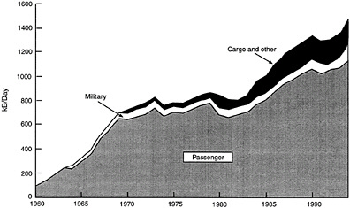
FIGURE 5-2 Demand for kerosene jet fuel in the United States. Source: Personal communication from C.L. Delaney and W.E. Harrision III, USAF Wright Laboratories, November 1996.
Despite these concerns, it is appropriate to address periodically opportunities for the development of a fire-safe fuel. Technical people tend to be optimistic about achieving the short-term goals but pessimistic about the long-term possibilities. It is possible that an AMK-type fire-safe fuel could be developed in the distant future. Against this backdrop, a brief discussion of jet fuels, fuel flammability, the fire problem (including fire prevention and protection techniques), cost/benefit analysis, and future aircraft trends follows.
JET FUELS
Jet fuels in the United States have been evolving since the 1940s (Martel, 1987). JP-1, the first jet fuel specified in the United States (1944), was a kerosene with a freeze point temperature of -77 °F and a minimum flash point temperature of 109°F. The availability of JP-1 was limited to about 3 percent of the average crude oil. JP-2 (1945) was an experimental fuel that was found to be unsuitable because of its viscosity and flammability.
JP-3 (1947 to 1951), the second operational fuel, had a high vapor pressure similar to aviation gasoline. Because of its high vapor pressure and because jet aircraft tend to fly at higher altitudes than reciprocating engine-powered aircraft, losses from fuel boil-off and vapor lock were problems.
JP-4 fuel (1951 to 1995), also designated as NATO F-40 and Jet B, a blend of gasoline and kerosene with a Reid vapor pressure restriction of 2 to 3 psi has fewer problems with boil-off and vapor lock. JP-4 has a freeze point of -77°F and a flash point temperature of about 0°F (not a specification requirement). JP-4 was the primary jet fuel used by the U.S.
Air Force from 1951 to 1995. In the mid 1980s an antistatic additive was added to JP-4 for fire-safety reasons.
JP-5 fuel (1952 to the present), also called NATO F-44, has a 140°F minimum flash point temperature. This kerosene fuel is currently the primary fuel used by the U.S. Navy and was developed mainly in response to fire-safety concerns on ships. JP-5 fuel has a freeze point temperature of -51°F and does not contain an antistatic additive.
JPTS (1956), developed for the U-2, is a highly refined kerosene with a low freeze point of -64°F and a thermal stability additive package (CJFA-5). Its minimum flash point temperature is 109°F.
JP-6 (1956), developed for the XB-70, is similar to JP-5 but has a lower freeze point (-66°F) and more thermal stability. The flash point temperature is not a specification requirement. JP-7 (1960s), developed for the SR-71, has a low vapor pressure and excellent thermal stability for high altitude and mach 3+ operations. It has a freeze point of -47°F and a minimum flash point temperature of 140°F.
Jet A and Jet A-1 (1950s to the present) are the two fuels used by commercial airlines. Both fuels have a 100°F minimum flash point temperature for fire-safety reasons. Jet A has a freeze point of -40°F and Jet A-1 has a freeze point of -53°F. Because of its lower freezepoint, Jet A is more widely available and is, therefore, more widely used. Commercial fuels in the United States are not required to contain antistatic additives and generally do not.
Finally, JP-8, also known as NATO F-34, was first introduced at NATO bases in 1978 and is currently the primary fuel used by the U.S. Air Force. JP-8 is very similar to Jet A-1, but it contains an icing inhibitor, a corrosion/lubricity enhancer, and an antistatic additive (see Table 5-2). The U.S. Air Force conversion to JP-8 was virtually complete in 1995 and was undertaken for fire-safety and combat survivability reasons.
FUEL FLAMMABILITY
The classic fire pyramid or fire tetrahedron (shown in Figure 5-3) illustrates the four elements necessary for a sustained hydrocarbon fire: heat for ignition, fuel, oxygen, and free radicals. The first three elements must be in the proper range and state for ignition and chain branching reactions must occur to maintain the reaction process. The first three elements must also be available in the proper balance for a sufficient period of time for ignition to occur. The required time increases near the flammability and ignition energy limits. All fire prevention, fire protection, or fire-safe fuel must negate at least one of these elements in some way. By this criterion, the two basic fuel properties used for first order assessments of a fuel's hazardous nature were established.
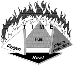
FIGURE 5-3 The fire pyramid.
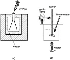
FIGURE 5-4 Autoignition temperature (AIT) and flash point temperature measurement apparatus.
The first and most important fuel property in many fire-safety scenarios is flash point temperature. Figure 5-4 is a simplified sketch of the equipment used to determine the flash point temperature of a fuel. The test fuel is placed in a container, the liquid fuel is slowly and uniformly heated and its temperature monitored. Periodically, as the temperature is increased, a large ignition source is inserted into the fuel container, until the lowest temperature at which a flash occurs is identified. This temperature is called the flash point and is
a measure of the availability of fuel vapors for ignition. In relation to the fire pyramid, the flash point temperature is a good estimate of the minimum fuel-air ratio necessary for ignition. The flash point temperature is close to, but slightly higher (5 to 10°F) than, the lower flammability limit. The flash point test involves downward flame propagation whereas the lower flammability limit test involves upward flame propagation. Because upward flame propagation is easier to achieve than downward flame propagation, it requires fewer fuel vapors at a lower temperature.
The apparatus used to determine the minimum autoignition temperature (AIT), or spontaneous ignition temperature, of a fuel is also illustrated in Figure 5-4. A 500-ml flask is slowly and uniformly heated. At a known temperature, a small amount of fuel is injected. This is followed by a 10-minute period during which any flash or light emitted from the flask is noted. This procedure is repeated a number of times with varying amounts of injected fuel at various temperatures to determine the lowest temperature at which an indication of ignition is observed.
In terms of the fire pyramid, the AIT of a fuel can be viewed as the lower limit at which a hot surface can cause ignition. Unfortunately from a fire-safety point of view, these two properties (flash point temperature and AIT) relate to each other in different directions for most fuels. For example, aviation gasoline (Grade-100) has a flash point temperature of -50°F (bad) and an AIT of 824°F (good). JP-8 has a flash point temperature of 100°F (good) and an AIT of 435°F (bad). In most real world situations, however, JP-8 is considered much less hazardous than aviation gasoline (see Figure 5-5 for the fuel hazard classification used by the National Fire Protection Association [NFPA] and in the Hazardous Substances Act). The relative fire hazard of a fuel can be better estimated from the flash point temperature than the AIT. However, many fuel combustion characteristics must be evaluated under real world conditions and then assessed against operational problems to evaluate potential fire hazard benefits as a function of fuel properties.
Can the number of aviation fatalities and injuries be reduced in a cost-effective manner by using a fuel with a higher flash point temperature, a lower probability of ignition in a crash situation, or some combination of other fuel properties? A commercial aviation switch to a higher flash point fuel (similar to JP-5) seems possible with reasonable effort and would result in some fire-safety benefits. An AMK-type fuel may have more potential fire-safety benefits, but a conversion of operational aircraft may be impractical in the final analysis. Before a conversion in initiated, detailed study of the aircraft fire problem covering these two fire-safe fuel approaches and their potential operational problems must be done.
Some fuel characteristics that should be assessed when evaluating the fire-safety benefits of a fuel are:
-
volatility/atomization
-
flash point
-
autoignition temperature (AIT)
-
flame spread rate over a pool
-
burning velocity (vapor-air mixture)
-
fuel-air mixture, including equilibrium and nonequilibrium (venting, sloshing, vibration, spray, mists, foams) conditions
-
electrical characteristics (static accumulation)
-
extinguishing characteristics
Some environments that should be considered when assessing the fire-safety benefits of a fuel are:
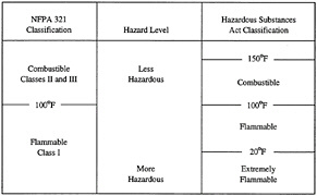
FIGURE 5-5 Flammable liquids classification from the National Fire Protection Association (NFPA) and Hazardous Substances Act as related to flash point.
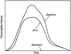
FIGURE 5-6 Rate of flammability volume buildup.
-
in-flight operations
-
ground operations
-
combat threats (projectiles, fragments, high explosive incendiary, etc.)
-
terrorist activities
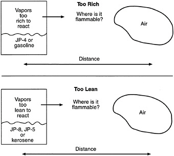
FIGURE 5-7 Flammable zone between leaking fuel-rich vapors and ambient air.
Figure 5-6 illustrates the relative rate of fuel-vapor generation and the flammability volume associated with a fuel spill at ambient conditions for kerosene, JP-4, and gasoline. Fuels with a flash point temperature above the ambient temperature have no flammable zone. Figure 5-7 illustrates the flammable zone between a leaking fuel rich mixture and ambient air. Leaking fuels with a flash point temperature above the ambient temperature have no flammable zone, assuming that no sprays or mists are present. Flammable regions for JP-4 under equilibrium conditions are shown in Figure 5-8, including the important flammable zone below the flash point temperature when sprays and mists may be present. The rates of flame spread across a spill of JP-4, JP-8, and JP-5 are shown in Figure 8. The flame spread rate is strongly dependent on flash point temperature. The flammability properties of several common aircraft fluids are given in Table 5-3, where the safe hot surface temperature is the temperature at which the probability of ignition is about 10-3 (Clodfelter, 1990).
THE FIRE PROBLEM
The general fire problem is the same for military and commercial aircraft, except for the combat threat to military
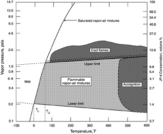
FIGURE 5-8 Flammable regions for JP-4.
aircraft (the projectile threat is illustrated in Figure 5-10). Some fire prevention, detection, and control measures are given in Table 5-4. In addition to the measures in Table 5-4, several active and passive fuel system and dry bay fire protection techniques have been studied over the years. Some of these techniques are listed below:
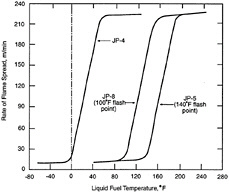
FIGURE 5-9 Flame spread across a jet fuel spill.
-
flame arrestor foam
-
inerting (nitrogen enriched air [NEA], N2, CO2, halon 1301 [CF3Br]) systems
-
explosion suppression systems
-
self sealing fuel tanks
-
crash resistance fuel tanks
-
dry bay protection (void filler materials, extinguishing systems, purge mats, powder packs)
-
fire proofing, fire resistance, fire hardening
-
gelled/emulsified fuels
-
antimisting kerosene (AMK)
-
fuel fogging
All but the last three protection techniques have been successfully used on operational aircraft. Flame arrestor foams have been used very successfully on many military fighter aircraftto prevent fuel tank explosions. Inerting systems are currently used to protect the fuel tanks of SR-71, C-5, OV-22, C-17, AH-64, and F-22 aircraft. As a result of the recent TWA 800 accident, fuel tank inerting systems will be conscientiously reconsidered for commercial aircraft.
COST/BENEFIT ANALYSIS
Changing fuels or adding fire protection hardware to an aircraft will require cost/benefit analysis prior to approval and
TABLE 5-3 Flammability Properties of Aircraft Fluids
|
|
Fuels |
Hydraulic |
Lubricants |
|||
|
|
JP-4 (Jet B) |
JP-8 (Jet A, Jet A1) |
JP-5 |
Mil-H 5606 |
MIL-H 83282 |
MIL-L 7808 |
|
Flash Point (°F) |
-10 to 10 |
100 |
140 |
210 |
435 |
425 |
|
Auto Ignition Temperature (°F) |
445 |
435 |
435 |
435 |
650 |
750 |
|
Lower Flammability Limit (vol pct) |
1.3 |
0.6 |
0.6 |
1.2 |
1.4 |
|
|
Upper Flammability Limit (vol pct) |
8.2 |
4.7 |
4.5 |
7.1 |
7.7 |
|
|
Hot Surface Ignitiona Temperature (°F) |
840 |
820 |
820 |
625 |
675 |
915 |
|
Safe Hot Surfaceb Temperature (°F) |
690 |
670 |
670 |
475 |
525 |
765 |
|
a Minimum based on six different references. b For bleed air ducts and fluids at ambient temperature. |
||||||
funding. A cost/benefit analysis for specific protection techniques may also include similar cost/benefit analyses for other prevention/protection techniques that may achieve the same safety goal. Some of the effects of fuel properties on aircraft operations/performance and fire safety are shown in Table 5-5. Unfortunately, in many cases, the fuel characteristics desired for optimal operation are different from those desired for optimal fire safety.
The factors in Table 5-5 should be included in any decision regarding a fuel change. In addition, a minimum number of operational factors regarding aircraft performance should be addressed. These include:
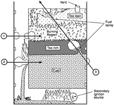
FIGURE 5-10 Fire problem associated with projectiles piercing the fuel tank.
-
cold engine starting (viscosity at low temperature, fouling/coking)
-
engine relight envelope (viscosity, vapor pressure, fouling/coking)
-
engine control anomalies (fouling/coking)
-
augmentor performance
-
engine maintenance (fouling/coking)
-
fuel transfer (viscosity, freeze temperature, vapor pressure)
-
fuel system maintenance
-
range (BTU density)
The following economic factors (at a minimum) should be considered:
-
price per gallon
-
ground handling (storage, transfer, special procedures and equipment)
The following strategic factors regarding fuel availability should be considered:
-
local
-
worldwide
-
interchangeability
The following safety factors should be considered:
-
ground handling (storage, transfer)
-
combat (fuel tanks, dry bays, weapons bays, engine compartments)
-
flight safety (fuel tanks, dry bays, engine compartments)
-
safety hazards
TABLE 5-4 Fire Prevention, Fire Detection, and Fire Control Techniques (MIL-F-87168)
|
Aircraft Fire Safety Goals |
Techniques |
|
Fire and Explosion Hazard Prevention |
Combustible material hazard reduction Subsystem hazard reduction Isolation Separation Ventilation Cooling Drainage Electrical Bonding and Lightning Protection Post crash fire prevention |
|
Fire and Explosion Hazard Detection |
Detection system location Performance Alarm output alerm set point and clearance |
|
Fire and Explosion Hazard Control |
Control adjacent area hazards Fluid control Ventilation termination Electrical ignition source control Fire barriers Fire hardening Smoke and hazardous vapor control Overheat control Fire extinguishing Ground fire fighting |
|
Source: Department of Defense, 1992. |
|
A cost/benefit analysis includes the cost of an item/system over its useful life compared to the benefits of the item/system during the same time period. The total cost or life cycle cost (LCC) of a system is the total cost at the end of its lifetime, including all expenses for research and development, production, modification, transportation, introduction of the item/system into the inventory, new facilities, training, performance, operations, support, maintenance, disposal, and any other
TABLE 5-5 Effects of Fuel Properties on Aircraft Performance and Fire Safety
|
Fuel Property |
Best for Operations |
Best for Fire Safety |
|
Heat of Combustion |
high |
low |
|
Flash Point |
depends |
high |
|
Viscosity |
low |
high |
|
Density |
high |
|
|
Atomization |
high |
low |
|
Vapor Pressure |
depends |
low |
|
Freeze Point |
low |
|
|
Thermal Stability |
high |
|
|
Resistivity |
unknown |
low |
costs of ownership penalties, less any salvage revenue at the end of its lifetime. LCC by itself is useful only when two or more competing items/systems provide the same total benefits or the same performance. On the other hand, the benefits of an item/system include performance enhancement, increased probability of mission completion, risk reduction benefits to personnel, equipment, facilities, products, lost revenue, and any other benefits during the ownership period.
The cost/benefit analysis involves determining the difference between prevention/protection system costs (LCC) and the benefits over a specific period of time, usually 20 years for aircraft systems. These costs and benefits will not occur in the same year. Therefore, all values must be converted to present value. For aircraft fire protection systems and fire-safe fuels, the parameters associated with a cost/benefit analysis are affected by the number and type of aircraft, the different types of air bases and airports affected, domestic vs. overseas operations, number of military and commercial aircraft affected, peace/war, sortie rate, flight hours, weight, volume, fuel costs, and performance factors.
FUTURE TRENDS
Research and development of aircraft fire-safety should be compatible with current and future treands in aircraft design.
Higher performance aircraft and higher thermally efficient engines are a given for the future. Also, composite fuel tanks have the potential for more effective fuel containment on ground impact. Heat sink requirements will increase because of increased electronic equipment cooling, hotter engines, and associated thermal loads. Because engines will be more efficient, there will be less fuel flow to the engines for cooling; therefore, more hot fuel will be recirculated to the fuel tanks.
The overall effects of these trends will be higher fuel system temperatures and higher engine surface temperatures. The upper limit for the fuel temperature at the engine combustor nozzles is about 325°F for current fuels. The Air Force is currently conducting operational tests on JP-8 fuel with antioxidant additives (personal communication with C.L. Delaney and W.E. Harrison III, USAF Wright Laboratories, November 1996). This test fuel is designated as JP-8+100. The ''+100" denotes an increase in the upper limit for the fuel at the combustor nozzles from 325°F to 425°F. In terms of fire safety, these trends mean a higher probability of flammable mixtures in fuel tanks with the current fuels, a higher probability of hot surface ignition, a faster buildup of flammable zones, and larger flammable zones associated with fuel release into aircraft compartments or on the ground.
SUMMARY
The search for a fire-safe fuel involves many complex operational issues and technical challenges. To be successful, a long-term commitment will be required. Given the always limited resources available to address safety concerns, the potential for the highest payoff, the greatest reduction in aircraft related deaths/injuries, must be determined in relation to the technical risks. It appears to this author that a switch to a higher flash point fuel similar to JP-5 is possible with reasonable effort and that this would result in some fire-safety benefits. An AMK-type fuel may have the potential for more fire-safety benefits, but a conversion to operational aircraft may be impractical in the final analysis. Fuel tank inerting and antistatic fuel additives may be the next big steps for improving the fire safety of commercial aircraft. In any case, a detailed study should be done of the aircraft fire problem and the two fire-safe fuel approaches and the potential operational problems of each before a fire-safe fuel program is initiated.
REFERENCES
Beery, G.T., R.G. Clodfelter, G.W. Gandee, D.M. Spear, and D.C. Wight. 1975. Assessment of JP-8 as a Replacement Fuel for the Air Force Standard Jet Fuel JP-4: Part I. AFAPL-TR-74-71. Wright-Patterson Air Force Base, Ohio: Air Force Aero Propulsion Laboratory.
Clodfelter, R.G. 1990. Hot surface ignition and aircraft safety criteria. Society of Automotive Engineers Transactions 99(4):521–539.
Coordinating Research Council (CRC). 1975. Aviation Fuel Safety 1975. CRC Report No. 482. New York: Aviation Fuel, Lubricant, and Equipment Research Committee, CRC.
Department of Defense (DOD). 1992. Fire and Explosion Hazard Protection Systems: General Specification for Aircraft. MIL-F-87168. Washington, D.C.: DOD.
Gandee, G.W., and R.G. Clodfelter. 1974. Evaluation of the Effectiveness of Anti-Mist Fuel Additives in Prevention of Aircraft Fuel Tank Ullage Fires and Explosions. AFAPL-TR-73-111. Wright-Patterson Air Force Base, Ohio: Air Force Aero Propulsion Laboratory.
Martel, C.R. 1987. Military Jet Fuels: 1944–1987. AFWAL-TR-87-2062. Wright-Patterson Air Force Base, Ohio: Air Force Wright Aeronautical Laboratories.
6
Rheology: Tools and Methods
Saad A. Khan, Joseph R. Royer, and Srinivasa R. Raghavan
Department of Chemical Engineering
North Carolina State University
INTRODUCTION
In this paper, we attempt to give the reader a basic understanding of rheology, a scientific discipline of great utility in characterizing complex, microstructured media. Rheology is formally defined as the study of deformation and flow behavior in various materials (Macosko, 1994). Since its humble origins in the 1920s in the laboratories of Eugene Bingham at Lehigh University, rheology has developed into a mature field of wide-ranging applicability.
Systems investigated using rheology can typically be classified as soft condensed matter or as complex fluids. Examples include macromolecular systems, such as polymer melts and solutions, gels, and biological fluids, as well as colloidal and multiphase systems, such as dispersions, emulsions, foams, and surfactant solutions. Typically, these materials are viscoelastic, i.e. they exhibit a combination of viscous and elastic properties. Such complex behavior cannot be characterized purely in terms of simple parameters, such as the material viscosity or elastic modulus.
One of the objectives of this paper is to indicate the possible applications of rheology towards designing improved aviation fuels. Although an aviation fuel typically behaves like a viscous liquid, the introduction of certain additives can cause the system to show a viscoelastic response (Hoyt et al., 1980). In that case, the rheology of the system becomes important, and rheological studies will be necessary for accurately modeling the flow in the aircraft engine. Moreover, it is possible that a controlled amount of viscoelasticity may prove to be beneficial to the overall performance of the aviation fuel. For instance, the addition of an "antimisting" component to the fuel can reduce the fire hazard in case of a fuel leak (Chao et al., 1984).
Our agenda for this paper is ambitious: we would like to cover the most important rheological principles, techniques, and methods, as well as indicate specific applications—all within about 20 pages. Clearly, we have to be very selective in the topics we choose to describe. Our focus will be on reviewing the material parameters obtained using rheology and the correlation of these parameters to material microstructure. In this context, the microstructure implies the spatial disposition of molecules, particles, or other entities in the system over length scales on the order of microns (Barnes, 1993). We will consider the three most common kinds of rheological techniques, viz. steady-shear rheology, dynamic rheology, and extensional rheology. We will then provide some specific examples for the applications of rheology to materials characterization and design. For the interested reader, we have supplied an extensive list of references for obtaining more detailed information on various aspects of rheology as well as on specialized rheological methods.
VISCOELASTIC BEHAVIOR
The science of rheology attempts to bridge the gap between solid mechanics (which deals with perfectly elastic solids) and fluid mechanics (which deals with perfectly viscous liquids). Thus, the rheologist is typically interested in viscoelastic systems that exhibit a combination of elastic and viscous behavior. To understand viscoelasticity, it will be helpful to consider first the cases of perfect elasticity or viscosity, which can be interpreted in terms of simple relationships such as Hooke's law for solids and Newton's law for liquids, respectively. We will now consider these two laws and indicate their applicability, or lack thereof, for various materials.
Fundamental relationships linking force and material deformation are called constitutive equations (Bird et al., 1987). For an elastic solid, the constitutive equation is Hooke's law, which states that the applied shear-stress (τ) is proportional to the produced shear-strain (γ) or alternately:
τ=Gγ
(1)
Here, the shear-stress (τ) is the shear force per unit area, and the strain (γ) is defined as the relative change in length. The proportionality constant (G) is called the shear modulus
and is an intrinsic property of an elastic solid. For Hookean solids when the stress is removed, the strain becomes zero and the material regains its original shape and structure. Thus, the elasticity of a material represents its ability to regain its shape and structure after deformation, i.e., to store deformation energy. Most metals and ceramics obey Hooke's law at small strains.
A similar constitutive equation exists for a viscous or Newtonian liquid. Newton's law of viscosity states that the shear stress (τ) is proportional to the rate of strain, or shear rate (![]() ).
).
![]() (2)
(2)
The proportionality constant (η) is defined as the viscosity of the material. Thus, a Newtonian liquid will undergo a constant rate of deformation under an applied stress, and when the stress is removed it will remain in the shape and structure it has adopted. The viscosity of a material is a measure of its internal resistance to flow and reflects the rate at which energy is dissipated in the material. Many small-molecule liquids, such as water, honey, and various oils, obey Newton's law.
As we have indicated, there are several materials that obey these constitutive equations. These materials can be completely characterized by measuring the respective parameters, G or η. But in reality, many systems, such as colloids, polymers, and gels, do not obey these simple constitutive relations. Instead, these materials have properties between those of a Hookean solid and a Newtonian liquid and can be classified as non-Newtonian or viscoelastic. For these materials, the viscosity is a function of shear-rate and, hence, not constant, and the shear modulus has two components signifying elastic and viscous character respectively.
Many simple experiments can demonstrate viscoelastic or non-Newtonian behavior (Boger and Walters, 1993; Bird et al., 1987; Schramm, 1994). First, consider "silly putty," which is a poly(dimethyl siloxane) (PDMS) elastomer of moderate molecular weight. When a ball of silly putty is dropped onto a solid surface, it bounces back like a rubber ball, thereby behaving almost like an elastic solid. However, if the putty is placed on that same solid surface for some time, it will slowly flow under the stress of gravity, thus showing behavior characteristic of a highly viscous fluid. Therefore, silly putty can behave both like an elastic solid or a viscous liquid, depending on the time scale of the deformation.
A second example of non-Newtonian behavior is "rod climbing" (or the Weissenberg effect). When a vertical rod is rotated in a container of Newtonian fluid, such as water, the inertial forces acting on the fluid cause it to move away from the rod. This creates a situation where the fluid level at the rod is lower than the fluid level at the container walls (Figure 6-1a). If the same experiment is run in a container of polymeric fluid, the flow changes directions and moves toward
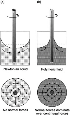
FIGURE 6-1 Rod climbing (Weissenberg effect). (a) In Newtonian fluids, centrifugal forces generated by the rotation push the fluid away from the rod. (b) In non-Newtonian fluids, normal forces are stronger than centrifugal forces and drive the fluid inward toward the rod.
the rod. This phenomenon is called rod climbing and is caused by the influence of normal stresses on flow properties (Figure 6-1b). These normal stresses create tension along the circular lines of flow and generate pressure toward the center, which drives the polymeric fluid up the rod.
Another dramatic illustration of viscoelastic effects is the "tubeless siphon" experiment. When a Newtonian liquid, such as water, is drained out of a container through a siphon, the tube must remain under the level of liquid in order for the liquid to continue to flow. However, a polymeric (non-Newtonian liquid) can continue to flow up and through the siphon even after the tube is raised above the liquid level (Figure 6-2). The fluid undergoes extensional flow (stretching) in this case, and the elastic nature of the polymeric fluid enables it to be extended upwards and sucked into the tube.
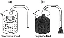
FIGURE 6-2 Tubeless siphon. (a) Newtonian fluid cannot be siphoned unless tube is below fluid level. (b) Normal stresses allow non-Newtonian fluid to be siphoned even when tube is above fluid level.
STEADY-SHEAR RHEOLOGY
Simple steady-shear flow is the easiest flow to generate and is, therefore, of central importance in rheology. Most of the rheological data reported in the literature is for steady-shear material functions. Moreover, flows occurring in a
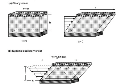
FIGURE 6-3 Two types of shear deformation. The arrows represent the velocity field in the fluid in each case. (a) Steady shear of a fluid between two parallel plates. At time t = 0, the system is at rest. At t > 0, the top plate is made to attain a constant velocity (v). (b) Dynamic (oscillatory) shear of a fluid between parallel plates. The top plate moves in a sinusoidal fashion with a maximum strain amplitude (γ0).
number of industrial processes, such as extrusion or flow-through circular dies, approximate steady-shear flow.
We will try to provide a basic understanding of steady-shear flow (Bird et al., 1987). In Figure 6-3a, two parallel plates are shown, between which lies a generic fluid. Suppose that both plates are initially at rest with no flow occurring. At a time t = 0, the upper plate is made to instantaneously attain a constant velocity (v). This results in the generation of a shear stress (τ) in the fluid from the cohesive forces between the fluid molecules. As the fluid flows, specific fluid elements (i.e., tiny packets of fluid that remain together at all times during the experiment) can be tracked as a function of time. It is easy to see that every fluid element will undergo the same strain, and that the local strain everywhere in the fluid will be equal to the overall shear strain. In the same way, the shear rate (![]() ) which is the rate of change of shear strain, can be shown to be constant throughout the fluid and equal to (v/h ). Thus, the shear rate applied on the system can be estimated from the velocity (v) applied to the top plate and the distance (h) between the plates.
) which is the rate of change of shear strain, can be shown to be constant throughout the fluid and equal to (v/h ). Thus, the shear rate applied on the system can be estimated from the velocity (v) applied to the top plate and the distance (h) between the plates.
From a steady-shear flow experiment, three material functions can be measured, viz. the viscosity (η), and the first and second normal-stress coefficients (ψ1 and ψ2). Among these, the viscosity (η) is the simplest and most important material
function and can be calculated from the measured shear stress (τ), and the applied shear rate (![]() ) by:
) by:
(3)
Note that this expression is analogous to Newton's law for simple liquids, with the caveat that the viscosity here (more properly termed the apparent viscosity) is a function of shear rate and not a constant parameter. The normal-stress coefficients (ψ1 and ψ2) are estimated in a similar manner by measuring the force per unit area exerted in directions normal to the direction of flow. However, they are much harder to measure accurately. The interested reader is referred to books by Ferry (1980) and Bird et al. (1987) for discussions of normal stresses.
Rheological experiments under steady shear are performed using "viscometric flows" that are indistinguishable from simple steady flow for all practical purposes (Dealy and Wissbrun, 1990). Thus, the three material functions that govern the behavior of the fluid (η, ψ1, and ψ2) can be obtained experimentally. Let us now examine some typical examples of material behavior under steady shear. We will focus on the most important material parameter, the steady-shear viscosity as a function of shear-rate, η(![]() ). Four types of behavior can be distinguished: Newtonian, shear thinning, yield stress (followed usually by shear thinning), and shear thickening. The last three are all examples of non-Newtonian or viscoelastic behavior.
). Four types of behavior can be distinguished: Newtonian, shear thinning, yield stress (followed usually by shear thinning), and shear thickening. The last three are all examples of non-Newtonian or viscoelastic behavior.
A plot of viscosity versus shear-rate or shear-stress is called a flow curve. It is common practice to plot the flow curve on a log-log plot as shown throughout Figure 6-4. The simplest type of steady-shear response is Newtonian behavior (Figure 6-4a), which implies a constant viscosity for the system, independent of shear rate. This is also manifested as a linear relationship between shear stress and shear rate (Newton's law), with the slope of the line defining the viscosity. Most low molecular-weight liquids and gases show Newtonian behavior.
Among non-Newtonian phenomena, the most widely observed is shear thinning, which implies a decrease in viscosity over a range of shear rates. This behavior is exhibited by most polymeric solutions and melts (Ferry, 1980), as well as by a large number of colloidal systems (Russel et al., 1989). In the simplest case, the sample shows Newtonian behavior at low shear rates and shear thinning at higher shear rates (Figure 6-4b). Thus, at low shear rates, the viscosity attains a constant value called the zero-shear viscosity (η0). However, as the shear rate is increased, there occurs a critical shear rate (![]() ), above which the viscosity of the sample decreases. Examples of shear thinning fluids include blood, saliva, various sauces, and creams.
), above which the viscosity of the sample decreases. Examples of shear thinning fluids include blood, saliva, various sauces, and creams.
Shear thinning sometimes occurs in conjunction with yield-stress behavior (Macosko, 1994). In this case, the system will not show any motion until a certain critical or yield stress (τy) is reached. Below the yield-stress, the viscosity of the material approaches infinity (Figure 6-4c), and the system responds in a plastic-like fashion. Above the yield stress, the material typically shows shear thinning. When viscosity is plotted versus shear rate, the existence of a yield stress is reflected as a characteristic slope of -1 in the low shear rate portion of the plot (Figure 6-4c). Some materials approximate Newtonian behavior beyond the yield stress, and these materials are called viscoplastics or Bingham plastics, after Eugene Bingham who first described paint this way in the 1920s. Materials that show a yield-stress appear to have a solid-like consistency when at rest, but when stirred or agitated, they can be made to flow quite easily. Food substances, such as mayonnaise, ketchup, and salad dressing, are good examples.
Modeling the steady-shear response has been a constant endeavor for rheologists. Several models have been formulated, particularly for shear thinning and yield-stress behavior. We will only mention two of the simplest and most convenient models. For shear thinning, the power-law model is most frequently used:
![]() (4)
(4)
The model contains two parameters, the consistency (K) and the power-law index (n). A value of n = 1 corresponds to Newtonian behavior; for shear thinning fluids n < 1. The simplest model that captures yield-stress behavior is the Bingham model used to describe viscoplastics:
![]() (5)
(5)
This model allows no motion below the yield stress (τy) and Newtonian flow behavior above τy. Numerous other models have been proposed for various shapes of flow curves, discussions of which can be found in Macosko (1994), Barnes (1993), and Larson (1988).
Shear thickening is a form of non-Newtonian behavior that is observed much less frequently (Barnes, 1989). As its name implies, shear thickening involves an increase in viscosity over a range of shear rates. This can be seen from Figure 6-4d, where the viscosity begins to increase at a critical shear rate, ![]() , until it reaches a maximum value at a shear-rate,
, until it reaches a maximum value at a shear-rate, ![]() , following which it begins to drop. The viscosity increase typically occurs over a narrow range of shear-rates. This is in contrast to shear thinning, where the viscosity can decrease continuously over several decades of shear rate. Shear thickening phenomena are observed in a few concentrated colloidal dispersions and some polymer solutions.
, following which it begins to drop. The viscosity increase typically occurs over a narrow range of shear-rates. This is in contrast to shear thinning, where the viscosity can decrease continuously over several decades of shear rate. Shear thickening phenomena are observed in a few concentrated colloidal dispersions and some polymer solutions.
In the examples given above, the flow curves represent equilibrium or steady-state behavior. Some materials, however, take a long time to reach steady state at constant shear,
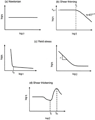
FIGURE 6-4 Examples of material behavior under steady shear (flow curves): (a) Newtonian; (b) shear thinning; (c) yield stress, shown in plots of viscosity vs. shear stress and shear rate; and (d) shear thickening.
i.e., their viscosity shows a continuous change with time of shear. The time-dependent phenomenon where the viscosity continuously decreases with time of shear is called thixotropy (Mewis, 1979). Thixotropic materials may also take considerable time to return to an at-rest state after being subjected to intense shear. These phenomena are widely observed in paints, adhesives, sealants, etc.
All rheological behavior, whether time-dependent or related to changes in shear, arises from changes in the microstructure of the system. This aspect will be a recurring theme in this paper. For example, consider a colloidal dispersion that shows yield stress and shear thinning. Such behavior typically signifies the presence of a particulate network structure in the system at rest and the shear-induced breakdown of the network into individual particles. The correlation between rheology and microstructure can be better understood after we discuss dynamic rheology and the linear viscoelastic response of different materials.
DYNAMIC RHEOLOGY
In dynamic shear flow (also called oscillatory shear), a sinusoidally varying deformation (strain) is applied to the sample (Ferry, 1980):
![]()
(6)
where γ0 is the strain-amplitude (i.e. the maximum applied deformation) and ∞ is the frequency of the oscillations. Figure 6-3b is a schematic representation of dynamic shear flow, and this can be compared to Figure 6-3a, which shows steady shear flow. The shear stress generated by the oscillatory shear will again be sinusoidal but will be shifted by a phase angle (δ) with respect to the strain waveform:
![]()
(7)
Using trigonometric identities, the stress wave can be decomposed into two components, one in-phase with the strain and the other out-of-phase by 90 degrees:
τ = τ0 cos(δ) sin(ωt) + τ0 sin(δ) cos(ωt)
(8)
We can rewrite the above expression in terms of two material functions (G´ and G´´):
![]()
(9)
(10)
(11)
The elastic modulus (G´), which is related to the stress in phase with the imposed strain, provides information about the elastic nature of the material. Because elastic behavior implies the storage of deformational energy in the system, this parameter is also called the storage modulus. The viscous modulus (G´´), on the other hand, is related to the stress component, which is completely out-of-phase with the displacement. This parameter characterizes the viscous nature of the material. Note that the out-of-phase component of the stress would be in phase with the sinusoidal deformation rate (![]() ). Because viscous deformation results in the dissipation of energy, the G´´ parameter is also called the loss modulus.
). Because viscous deformation results in the dissipation of energy, the G´´ parameter is also called the loss modulus.
A purely elastic material would exhibit a non-zero elastic modulus and a viscous modulus G´´ = 0. In contrast, a purely viscous material would show a show a zero elastic modulus, and its stress response would be 90 degrees out-of-phase with the strain (γ) and in-phase with the shear rate (γ). A viscoelastic material will exhibit non-zero values for both G´ and G´´. The above analysis assumes that the measurements are made in the "linear viscoelastic" (LVE) regime of the sample under consideration (Ferry, 1980). The conditions for linear viscoelasticity are that the stress be linearly proportional to the imposed strain and that the torque response involve only the first harmonic. The first condition requires that the moduli G´ and G´´, in the LVE regime, should be independent of the strain-amplitude. The absence of higher harmonics in the stress response, as stipulated in the second condition, ensures that the response remains sinusoidal.
If these two conditions are met, the elastic and viscous moduli would truly be material functions. They would, however, be functions of the frequency of oscillation (∞). A plot representing the moduli as a function of frequency, i.e., G´ (∞) and G´´(∞), is called the dynamic mechanical spectrum of the material. Such a plot is extremely useful because it represents a signature of the microstructure in the material. We can also define several auxiliary parameters based on the quantities derived above (Ferry, 1980). One such parameter is the complex viscosity (η*), which is defined as:
(12)
The variation of complex viscosity with frequency is analogous to the variation of steady viscosity versus shear-rate. (Note that both frequency and shear-rate have units of s-1). Empirical correlation rules between the steady and complex viscosities, indicate a link between steady and dynamic rheology (Cox and Merz, 1958; Doraiswamy et al., 1991; Raghavan and Khan, 1997).
The two dynamic moduli G´ and G´´ represent a clear distinction between elastic and viscous behavior in the same material. This helps to clarify the viscoelastic nature of a given sample. A simple model that captures the essential features of linear viscoelastic behavior is the Maxwell model, originally proposed by James Clerk Maxwell in 1867. In this model (shown in Figure 6-5), a viscoelastic sample is assumed to have two distinct elements: an elastic spring and a viscous dashpot connected in series (Macosko, 1994). The elastic spring has a shear-modulus (G0), and the viscous component has a viscosity (η0).
A characteristic parameter of a viscoelastic system is its relaxation time (λ), which in the case of the Maxwell model is equal to η0/G0. The relaxation time is a measure of the time required for stresses to relax in a viscoelastic material. Recall that under deformation, the stresses relax instantaneously for a viscous liquid; they never relax for an elastic solid. The Maxwell model is useful for simple viscoelastic systems, such as polymer solutions or melts, which exhibit a single relaxation time. We should mention that there are specific experiments to probe relaxation behavior, e.g., stress relaxation after a step strain, creep at constant stress, etc. A discussion of these experiments falls beyond the scope of this paper; details can be found in Bird et al. (1987), Ferry (1980) and Macosko (1994).

FIGURE 6-5 Maxwell model for a viscoelastic material. The system is considered to be a series combination of two distinct segments: an elastic spring (modulus G0) and a viscous dashpot (viscosity η0).
Perhaps the most important advantage of dynamic shear is that it allows us to characterize microstructures without disrupting them in the process. The net deformation imposed on the sample is minimal because the experiments are restricted to small deformations (strain amplitudes) within the LVE regime of the sample. As a result, the linear viscoelastic moduli reflect the microstructures present in the sample at rest. This is to be contrasted with steady shear, where the material functions are always obtained under flow conditions that correspond to relatively drastic deformations. Consequently, the microstructure under steady flow will be very different from the microstructure under static conditions. We can, therefore, correlate dynamic rheology to static microstructures and steady rheology to changes in microstructure caused by flow.
We will now illustrate the types of responses seen in dynamic frequency spectra, and furthermore, the correlation of these responses with material microstructure. We will also point out the steady-shear rheological behavior corresponding to these microstructures. Two classes of materials will be considered, colloidal dispersions and polymer melts. Colloidal dispersions are obtained by dispersing solid, colloidal-sized particles in a liquid (which, for simplicity, is assumed to be a purely viscous medium). The extent to which the particles flocculate depends on the strength of colloidal interaction forces between them (Russel et al., 1989). Various microstructures are thus possible, as illustrated in Figure 6-6.
In the simplest dispersions, inter-particle forces are negligible, i.e., each particle is discrete and does not "feel" the presence of its neighbors. These are classified as "non-flocculated" or stabilized dispersions. The typical dynamic rheological response of these systems (Figure 6-6a) consists of a dominant viscous modulus (G´´) which exceeds the elastic modulus (G´) over the complete range of experimental frequencies (Macosko, 1994). The slopes of the G´—ω and G´´—ω lines are often close to 2 and 1 respectively (note that frequency spectra are typically plotted in a log-log fashion as were the steady-shear flow curves). Under steady flow, the zero-shear viscosity of these dispersions will be relatively low, and the systems will show Newtonian or shear thickening behavior. (The concentration of solid particles has to be very high for shear thickening to occur). Note that the addition of colloidal particles always leads to an increase in viscosity over the pure liquid, but only a moderate increase is observed if the particles are non-interacting.
If the inter-particle forces are fairly strong, there will be a tendency for the particles to adhere to one another and form larger structures called aggregates or flocs (Mewis and Spaull, 1976). A flocculated microstructure is shown in Figure 6-6b along with its characteristic frequency spectrum. Note that G´ becomes larger than G´´ at high frequencies but remains smaller at low frequencies. Both quantities show a weaker dependence on frequency, with lower slopes in the terminal zone (as compared to Figure 6-6a). Thus, dynamic rheology shows the viscoelastic nature of these systems as they exhibit comparable elastic and viscous character. The viscosity of a flocculated dispersion greatly exceeds the viscosity of a non-flocculated system. The steady-shear response is non-Newtonian and shear thinning, corresponding to the breakup of flocs into smaller and smaller units until they are reduced to individual particles.
Under conditions of strongly attractive inter-particle forces and high particle concentrations, flocculation of the system will be significant. Ultimately, the flocs will overlap with one another until a single floc fills the whole volume (Macosko, 1994). This corresponds to a situation where a three-dimensional network of particles extends throughout the system. A system containing a network-type microstructure is called a gel. The dynamic mechanical spectrum of a gel shows a frequency-independent elastic modulus (G´) that greatly exceeds the viscous modulus (G´´) (Figure 6-6c). Thus, a gel behaves principally as an elastic material because of the presence of a continuous network. The level of elastic modulus (G´) can be correlated to the rigidity (i.e., the density of cross-links) in the network. In steady shear, a gel will show a yield stress at low shear, followed by shear thinning at higher shear rates. The yield stress signifies that a minimum stress is required to disrupt the cross-links in the network. Shear thinning reflects the progressive reduction in floc size as a result of shear.
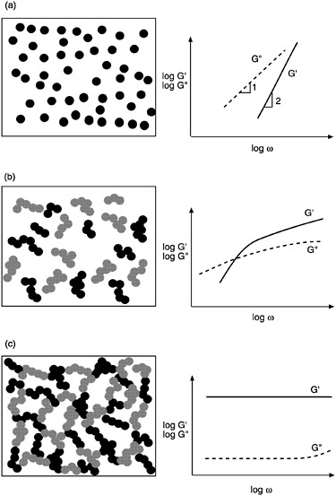
FIGURE 6-6 Dynamic rheology and microstructure of colloidal dispersions. In each case the frequency spectra (G´ and G´´ as functions of frequency ω) are shown with their corresponding microstructure. (a) Stabilized dispersion. (b) Weakly flocculated dispersion. (c) Strongly flocculated dispersion (gel).
We now consider the dynamic rheology of polymer melts over a range of molecular weights. This leads us to a consideration of "time-scales," a factor we largely ignored in the case of colloidal dispersions. Polymer melts can show very different behavior depending on the time-scales (or equivalently, the frequencies) probed in a rheological experiment (Dealy and Wissbrun, 1990). Note that low frequencies correspond to large time-scales and vice-versa. A typical rheological experiment may be conducted in the frequency range of 10-2 to 102 rad/s, but data over a larger span of frequencies can be obtained by a procedure called time-temperature-superposition (TTS) (Ferry, 1980). This procedure utilizes the equivalence of time and temperature in the rheological context, i.e., dynamic rheological data obtained at higher temperatures is equivalent to data at longer time-scales (lower frequencies). Using TTS, we can generate data for a high molecular weight, monodisperse polymer melt over an extremely wide range of frequencies (10-5 to 104 rad/s), as illustrated schematically in Figure 6-7.
The plot shown in Figure 6-7 (note that both axes are on logarithmic scales) can be divided into three regions (Ferry, 1980). Region I corresponds to low frequencies (i.e., long time-scales) and is called the terminal region. It represents the frequency range that is experimentally accessible at any given temperature. We find that in the terminal zone both G´ and G´´ increase steadily with frequency and the viscous modulus G´´ is larger than the elastic modulus G´. The relations G´~ ω2 and G´´~ ω are typically found to be valid in this region, leading to slopes of 2 and 1 respectively for the lines. In Region II, the moduli cross over at a critical frequency, ωc, and G´ becomes greater than G´´. The inverse of ωc corresponds
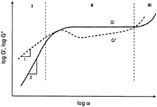
FIGURE 6-7 Dynamic mechanical spectrum (G´ and G´´ as functions of frequency ω) for a typical polymer melt over a wide range of frequencies (typically 10-3 to 104 rad/s). The expanded frequency range is made possible by time-temperature-superposition (TTS). Region I is the terminal zone. Region II is the crossover/plateau region. Region III is the high-frequency regime.
to the longest relaxation time for the polymer melt. The curves also begin to flatten and G´ plateaus off at a value given by ![]() (plateau modulus). Finally, in Region III, the moduli again increase with frequency, although to a smaller extent than in the terminal zone.
(plateau modulus). Finally, in Region III, the moduli again increase with frequency, although to a smaller extent than in the terminal zone.
The existence of a plateau in the frequency spectrum is caused by the presence of entanglements in the polymer melt. Entanglements can be envisioned as kinks in the polymer chain caused by segment to segment contacts with neighboring chains (Ferry, 1980; Macosko, 1994). The effect of entanglements is significant only for polymers with a molecular weight that exceeds the entanglement molecular weight (Me). The length of the plateau region gives an indication of the extent of polymer chain entanglement. Thus, for a lower molecular-weight melt, the plateau region would be much smaller in width, and the crossover of G´ and G´´ would occur at a higher frequency (smaller relaxation time).
The steady-shear rheology of a polymer melt is very sensitive to its molecular weight (Ferry, 1980; Bird et al., 1987). Low molecular weight melts are Newtonian liquids. As the molecular-weight increases, shear thinning begins to occur beyond a critical shear rate (![]() ). The curves resemble the schematic shown in Figure 6-4b (and again in Figure 6-10) with a viscosity plateau (η0) followed by shear thinning. As the molecular weight increases, shear thinning begins to set in at lower shear rates. From a microstructural point of view, shear thinning reflects a decrease in the density of entanglement with increasing shear because of progressive stretching and uncoiling of polymer chains (Ferguson and Kemblowski, 1991). An important trend in polymer rheology is the increase in zero-shear viscosity (η0) with molecular weight (M) of the polymer melt (Ferry, 1980):
). The curves resemble the schematic shown in Figure 6-4b (and again in Figure 6-10) with a viscosity plateau (η0) followed by shear thinning. As the molecular weight increases, shear thinning begins to set in at lower shear rates. From a microstructural point of view, shear thinning reflects a decrease in the density of entanglement with increasing shear because of progressive stretching and uncoiling of polymer chains (Ferguson and Kemblowski, 1991). An important trend in polymer rheology is the increase in zero-shear viscosity (η0) with molecular weight (M) of the polymer melt (Ferry, 1980):
(13)
Thus, η0 is initially proportional to the molecular weight but increases more sharply once the entanglement molecular weight (Me) is exceeded. This indicates the critical role played by entanglements in polymer science.
RHEOLOGICAL MEASUREMENTS (STEADY/DYNAMIC SHEAR)
So far, we have indicated the two most important types of rheological techniques, i.e., steady shear and dynamic (oscillatory) shear. We have concentrated on a few important material functions, viz., the steady viscosity (η), and the dynamic moduli (G´ and G´´). In this section, we briefly describe how these parameters are measured in practice. Rheological measurements are typically performed on a rheometer. There are several categories of rheometers, with the most prominent being capillary rheometers (which utilize
pressure-driven or Poiseuille flows) and rotational rheometers (which use drag flows). Capillary rheometers are capable of measuring only the steady-shear properties of a fluid, not the dynamic rheological properties. For this reason, we will focus solely on rotational instruments.
Two types of rotational rheometers exist: stress-controlled rheometers and strain-controlled rheometers (Ferguson and Kemblowski, 1991; Schramm, 1994). In a strain-controlled rheometer, a known deformation (strain or shear rate) is applied to the fluid, and the stress is detected. Typically, the strain is applied by rotating one segment of the geometry, and a transducer connected to the other segment measures the stress. A stress rheometer operates in the opposite fashion, by applying a controlled stress and measuring the resulting deformation. In the past few years, stress rheometers have become immensely popular because of their great sensitivity and wide torque range. Rotational rheometers also can use a multitude of different geometries. Concentric cylinder (Couette), parallel plates, and cone-and-plate are the most common geometries. For the purpose of illustration, we will consider the use of a cone-and-plate geometry on a strain-controlled rheometer and show how rheological quantities are calculated.
A schematic diagram of a cone-and-plate geometry is shown in Figure 6-8. The device consists of a small-angle
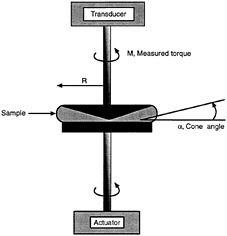
FIGURE 6-8 A rheological experiment on a cone-and-plate geometry on a strain-controlled rotational rheometer. The cone has a radius (R) and cone angle (α), and its edge is truncated up to a height of 50 microns. The actuator applies a controlled deformation to the bottom plate, and the transducer connected to the cone measures the response of the sample.
cone and a flat plate. The cone angle is denoted to be , and the radius of the cone/plate is R. This geometry has several advantages: it requires only a small sample and is easier to load and clean than more complex geometries (Macosko, 1994). More importantly, a homogenous deformation is maintained throughout the sample, provided the cone angle is small (<0.2 radians). Flow is generated in a rotational geometry by moving one of the walls of the system in such a way that the fluid is dragged along with the wall. This explains why these flows are called "drag flows" (Ferguson and Kemblowski, 1991).
In Figure 6-8 we show schematically how a test would be run on a cone-and-plate geometry using a strain-controlled rheometer. The general principle is to input a deformation and measure the torque output. The raw data can be converted into rheologically relevant quantities using the physical dimensions of the cone (R, α) and the input parameters. Let us first consider a steady-shear experiment. In this case, the actuator rotates the bottom plate at an angular velocity Ω (rad/s). The shear-rate exerted on the sample is given by (Macosko, 1994):
![]()
(14)
The response of the sample is measured by the transducer in terms of a torque (M). The torque can be converted into a shear-stress (τ) as follows:
![]()
(15)
The apparent viscosity can then be calculated from the shear-stress and shear-rate by using the expression ![]() . Thus,
. Thus,
(16)
In dynamic measurements, the bottom plate is oscillated from its mean position, with the peak displacement being up to an angle Φ (in radians). The strain-amplitude is then given by (Macosko, 1994):
![]()
(17)
The response of the sample is in terms of a sinusoidal torque showing a phase lag with respect to the input strain. The peak torque (M), and the phase angle (δ), are measured by the instrument. The peak stress-amplitude (τ0) is calculated from the peak torque (M) using Eq. 15. The elastic and viscous moduli can then be calculated using Eqs. 9 and 10 respectively. The final expressions are:
(18)
(19)
Similar governing equations can be derived for other geometries (Macosko, 1994; Whorlow, 1992). It is important to note that these equations are obtained directly form the physical laws of motion. The rheological quantities calculated using these equations are, therefore, independent of any constitutive model.
EXTENSIONAL RHEOLOGY
In the previous sections we considered steady-shear and dynamic shear, which are by far the most common types of rheological techniques. Most texts on rheology are devoted primarily to shear flow, and most laboratories are equipped only with shear rheometers. However, many viscoelastic phenomena are better perceived in extensional (elongational) flow, which is fundamentally different from shear flow. For simplicity, we will confine our discussion to steady uniaxial extension. (In the case of dynamic rheology, the type of deformation, i.e., shear versus elongation, is not important, because we consider only small deformations).
Uniaxial extension can be visualized to occur when a rod of fluid is gripped on each end and pulled (Figure 6-9) (Macosko, 1994; Dealy and Wissbrun, 1990). In the process, the sample is extended along the direction of imposed deformation and gets constricted along the two perpendicular directions. Thus, a cylindrical fluid element becomes longer and thinner as it is stretched. One of the main problems in extensional rheometry is the difficulty of achieving steady extensional flow, especially for low viscosity liquids. In discussing steady shear, we showed how a constant shear-rate could be imposed simply by moving the top plate at a constant velocity (v) (Figure 6-3a). However, to apply a constant elongation rate (![]() ) the ends of the cylindrical sample shown in Figure 6-9 have to be moved at an exponentially-increasing velocity, given by (Macosko, 1994):
) the ends of the cylindrical sample shown in Figure 6-9 have to be moved at an exponentially-increasing velocity, given by (Macosko, 1994):
(20)
L0 is the initial length of sample. The sample length (L) increases exponentially with time, while the area of the end
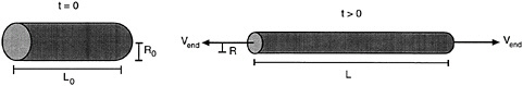
FIGURE 6-9 Uniaxial extensional flow on a cylindrical fluid element. Initially, the fluid is at rest, while at time t > 0, it is stretched by pulling the ends at a velocity (vend). Note that the cylindrical sample becomes longer and thinner as it is stretched.
-surface (A) decreases exponentially (assuming that the material is incompressible, so that the sample volume would not change). The stress causing the sample to elongate is the normal stress difference (Txx-Trr) which is the force (f) per unit area acting on the end of the sample. The extensional viscosity is obtained by dividing the normal stress by the elongation rate (![]() ).
).
(21)
From this discussion, we can appreciate the difficulties involved in designing an extensional rheometer, e.g., in designing clamps that move at an exponential pace to maintain a constant deformation. Other problems are the generation of a purely extensional flow free of shear effects and gravity effects. New rheometer designs (e.g. ''opposing jets") are being developed to solve these problems (Macosko, 1994). Despite the difficulties, extensional rheology is worth studying for several reasons. Flows occurring in industrial processes, such as injection molding, extrusion, and calendering, often have a strong elongational component. Also, several viscoelastic phenomena including the tubeless siphon pointed out earlier are mainly elongational effects.
The behavior of a material under extension cannot be directly extrapolated from its behavior under shear. Consider the rheology of a polymeric melt under steady-shear as well as extension, as represented schematically in Figure 6-10. The steady-shear viscosity η is constant at low shear rates and decreases at higher shear rates (shear thinning behavior). The extensional viscosity (ηe) is also a constant at low elongation rates, but ηe increases at higher ![]() . Within the regime of constant ηe, its value is three times the zero-shear viscosity (η0).
. Within the regime of constant ηe, its value is three times the zero-shear viscosity (η0).
![]()
(22)
This result, sometimes called Trouton's rule, was originally found by F.T. Trouton in 1906 and can be predicted from the continuum mechanics of the various flows. The increase in ηe at higher deformations is called extensional-thickening and occurs for melts of polymers, such as polystyrene and low-density polyethylene. Thus, the same material can show shear
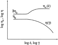
FIGURE 6-10 Typical behavior of a polymer melt under steady shear and steady uniaxial extension. Under steady shear the sample shows shear thinning; under extension it shows extensional thickening.
thinning under shear flow and extensional-thickening under elongational flow.
Extensional measurements can be more sensitive to small changes in the system composition than shear rheology. This is particularly true for polymer solutions containing very small amounts of polymer (in the 100 to 1000 ppm range), which show purely viscous behavior under shear and viscoelastic effects under extension (Chao et al., 1984). Similarly, solutions of associative polymers show anomalous effects that are much more pronounced under extension than under shear (Ballard et al., 1988).
RHEOLOGY OF SILICA DISPERSIONS
In the next two sections, we provide a few examples of the use of rheology for characterizing and designing complex materials. We first consider the rheology of fumed-silica dispersions in oligomeric liquids, such as low molecular-weight glycols. These disperse systems have potential applications in state-of-the-art technologies, including "cable gels" for fiber-optic cables and composite polymer electrolytes for rechargeable lithium batteries (Khan et al., 1991; Khan and Zoeller, 1993). Colloidal dispersions can exhibit complex microstructures, as we pointed out in the previous section. The microstructure is a direct result of colloidal interactions between the particles, and therefore, varying the surface chemistry of the particles can have a significant effect on the microstructure. Because rheology is highly sensitive to microstructure, it is an invaluable tool for studying the origins of microstructural changes.
As an illustration, consider Figure 6-11 where we show the steady-shear rheology of two silica dispersions in the same liquid (a polypropylene glycol). Each dispersion has the same concentration of silica; the only difference is in the surface chemistry of each silica. One of the silicas (A200) is hydrophilic because of the presence of surface hydroxyl groups. This silica gives rise to a relatively low viscosity at low shear rates, and to shear thickening at higher shear rates. The other silica (R805) is hydrophobic, having an appreciable fraction of non-polar (octyl) surface groups. Its corresponding dispersion shows shear thinning over the entire range of shear-rates, and the viscosity at low shear rates is significantly higher than for the A200 silica dispersion.
In order to study the at-rest microstructures, we resort to dynamic rheological measurements. We show the elastic (G') and the viscous (G") moduli as a function of frequency in Figure 12 for the same systems shown in Figure 6-11. For the A200 (hydrophilic) silica dispersion, the viscous modulus (G") is greater than G' over the entire frequency range. Moreover, both moduli depend strongly on frequency. This signifies a non-flocculated microstructure composed of distinct particles (Figure 6-6a). In contrast, for the R805 (hydrophobic) silica dispersion, the moduli are independent of frequency, and the elastic modulus (G') exceeds G" over the entire frequency range. This frequency spectrum signifies that the latter system is a flocculated gel with a three-dimensional network structure.
We can form a picture of the colloidal interactions present in each dispersion by considering the steady and dynamic responses together. The A200 (hydrophilic) silica exists as
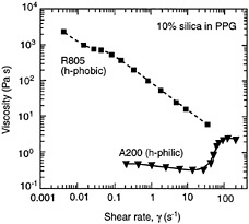
FIGURE 6-11 Steady shear viscosity (η) as a function of shear rate for two colloidal dispersions. Each dispersion contains 10 percent fumed silica in a poly(propylene glycol) of molecular weight 425 g/mol. The two silicas differ only in their surface chemistry, with one of them being hydrophilic and the other hydrophobic.
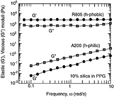
FIGURE 6-12 Elastic (G') and viscous (G") moduli as a function of frequency for the fumed-silica dispersions shown in Figure 6-11.
isolated particles that exhibit little or no tendency for flocculation. Consequently, the system behaves like a viscous fluid, as evidenced by the dominant G" in its frequency spectrum (Figure 6-12) as well as its low zero-shear viscosity (Figure 6-11). It appears that the hydrophilic A200 surface preferentially interacts through hydrogen bonding with the polar groups present on the glycol, leading to steric stabilization of the particles (Raghavan and Khan, 1997). This contributes to an effective repulsive interaction between the particles, which acts as a barrier to flocculation. In contrast, the non-polar groups present on the R805 (hydrophobic) silica can interact with each other through van der Waals dispersion forces (Raghavan and Khan, 1995). This leads to the flocculation of silica particles, as shown by a pronounced elastic response in the dynamic data (Figure 6-12) and high viscosities under steady shear (Figure 6-11). The shear thinning of the R805 dispersion is caused by progressive reduction in floc size due to shear.
We would also like to comment briefly on the microstructural origins of shear thickening. This is a reversible flow-induced phenomenon where the viscosity increases under flow but where the system reverts back to its low-viscosity state at rest (Barnes, 1989). Current experimental and theoretical investigations have confirmed that shear thickening is caused by the formation of temporary clusters under flow (Raghavan and Khan, 1997). These "hydrodynamic clusters" are formed by the action of hydrodynamic forces that squeeze particles together into larger groups (Bossis and Brady, 1989). In order for these clusters to be formed, the hydrodynamic forces (which increase steadily with shear-rate) first have to overcome the steric repulsion forces. Therefore, shear thickening occurs only beyond a critical shear rate, as seen in Figure 6-11.
RHEOLOGY OF ASSOCIATIVE-POLYMER SOLUTIONS
We now proceed to consider the rheology of polymeric systems formed by dissolving an "associative polymer" in water. An associative polymer is typically a water-soluble polymer that also possesses hydrophobic groups (Hansen et al., 1996). Small amounts of these polymers can greatly increase the viscosity of aqueous media, due to strong interactions between the hydrophobic groups. Thus the concentration, type, and length of the hydrophobic moiety are important in determining the properties of the system. In our laboratories, we have done extensive work on aqueous solutions of hydrophobically modified alkali-soluble emulsion (HASE) polymers. These polymers possess a comb-like structure, with pendant hydrophobic groups sticking out of the polymer backbone (English et al., 1997a).
We will briefly look at two effects, polymer concentration and the presence of surfactants. In Figure 6-13, we show steady-shear data (viscosity as a function of shear-stress) for aqueous solutions containing different polymer concentrations. As the concentration is increased from 0.4 to 1.0 g/dl, the zero-shear viscosity (η0) increases by a factor of 1000. In fact, if we plot η0 versus polymer concentration (c) we find that (η0 ~ c8, a much more dramatic increase than for regular polymers, for which η0 ~ c3.4 (scaling similar to the variation of η0 with melt molecular weight). Note also that there are basic differences between the shapes of the viscosity curves at low concentrations and high concentrations. At low concentrations, the initial Newtonian plateau is followed by an intermediate range of mild shear thickening and then a region of drastic shear thinning. At high concentrations, the shear thickening is no longer observed but a viscosity plateau exists at intermediate stresses. Also, the viscosity drops abruptly by
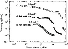
FIGURE 6-13 Steady shear viscosity (η) as a function of shear stress for aqueous solutions of an associative polymer. Data is shown for three different polymer concentrations.
orders of magnitude at a higher stress(behavior reminiscent of a pseudo yield-stress.
Clearly, the rheology of associative polymer solutions is much more complex than the simple cases we have considered thus far. This is because hydrophobic interactions can be either intrapolymeric (between hydrophobes on the same chain) or interpolymeric (between hydrophobes on adjacent chains), with a combination of both mechanisms at any given stress level. We believe that the dominant mode of interaction is intrapolymeric at low stresses and interpolymeric at intermediate stresses (English et al., 1997). The interpolymeric interactions contribute to shear thickening and to the viscosity plateau (Ballard et al., 1988). At very high stresses, all hydrophobic interactions are precluded, as the hydrodynamic forces in the system begin to dominate. The transition from a state of appreciable interactions to negligible interaction occurs at the pseudo yield-stress.
Another significant effect in these systems is caused by the presence of surfactant. Consider an aqueous solution of HASE polymer at a polymer concentration of 0.6 g/dl (Figure 6-14). The elastic modulus (G´) for this system varies with frequency as ω0.8 (at low ω) and exceeds the viscous modulus (G´´) only at high frequencies. When we add 1.5 g/dl of a non-ionic surfactant to the system, we find that the levels of both G´ and G´´ are increased. Moreover, the elastic modulus (G´) shows plateau-like behavior over most of the frequency range and is higher than the viscous modulus (G´´) over the entire spectrum. This indicates that the addition of surfactant renders the system more elastic. We conjecture that this behavior is caused by enhanced
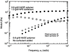
FIGURE 6-14 Elastic (G´) and viscous (G´´) moduli as a function of frequency for two associative polymer solutions. In one system only polymer is present; the other contains 1.5 g/dl of a non-ionic surfactant (NP6) in addition to polymer. The steady-shear data for the polymer solution in the absence of surfactant was shown in Figure 6-13.
hydrophobic interaction in the system, with the surfactant molecules acting as links between polymer hydrophobes. Note that the molecular structure of the surfactant is crucial to its behavior; other types of surfactants can produce the reverse effect, i.e., they can reduce the elastic character of the system.
RHEOLOGY OF AVIATION FUELS
Currently, the fuels used in the gas-turbine engines of commercial aircraft are kerosene-based jet fuels (Hutchinson, 1995). The two main types are Jet A fuel, used in North America, and Jet A-1, used in most other regions of the world. Jet fuels are among the most tightly specified products of oil refineries, the specifications involving boiling point, water content, aromatic content, etc. The important qualities jet fuels must generally exhibit under all operating conditions are as follows (Kroes and Wild, 1995):
-
pumpability and ease of flow, with negligible volatility
-
efficient combustion and high calorific value
-
adequate lubrication for the moving parts of the engine
-
minimal corrosive effects, fire hazards, etc.
The viscosity of an aviation fuel is a factor in calculating pressure drops in fuel lines, through its relationship to the Reynolds number (Bird et al., 1987). A lower viscosity corresponds to smaller pressure drops and lower pumping requirements. The viscosity increases with decreasing temperature, and when the freezing point of the fuel is approached, waxy particles begin to form. Many fuel specifications, therefore, include a maximum viscosity limit at low temperatures to ensure pumping and flow capabilities (CRC report, 1984). Research on aviation fuels has also led to the development of additives for specific purposes, e.g. to prevent ice and bacterial contamination in the fuel or to reduce the buildup of static charge (Kroes and Wild, 1995).
One class of additives is intended to reduce the flammability of aviation fuels in the event of an accident or crash. These additives, called "antimisting" (AM) agents, are essentially linear polymers of high molecular weight (> 106) (Chao et al., 1984). A small amount of polymeric additive (100 ppm) is sufficient to reduce the formation of atomized droplets or "mist." Droplets in sprays of antimisting fuels tend to be larger and, in some cases, deformed to strings or filaments (Hoyt et al., 1980). The reduction of surface area available for vaporization, combined with the greater distance between droplets, inhibits flame propagation.
The antimisting behavior of fuels containing polymeric additives is a consequence of the viscoelastic nature of the fuel system (Hoyt et al., 1980; Chao et al., 1984). Accordingly, it is important to study the rheology of AM fuels. Under shear flow, however, non-Newtonian effects cannot
be detected for these systems because of the low level of polymer concentrations. On the other hand, the appearance of filaments in antimisting fuel sprays is an indication that there is a strong elongational component in spray hydrodynamics. This points to the significance of extensional rheology in AM fuels. Chao et al. (1984) attempted to correlate the extensional viscosity (ηe) of the fluid to its antimisting behavior. They resorted to an indirect, yet simple and inexpensive indicator of η e, viz., the ductless siphon height. The height (h*) to which a viscoelastic fluid can raise itself in the absence of an immersed duct (see Figure 6-2) can be taken as a measure of the fluid's extensional viscosity (ηe). The researchers found that AM fuels showing large values of the ductless siphon height (h*), and thereby ηe, also exhibited strong antimisting behavior. Moreover, as the polymer molecular weight or concentration in solution was increased, the fuel became more viscoelastic (greater h*), and the antimisting action was enhanced.
One of the penalties of using polymeric additives in fuels is the increased viscosity of the system (Chao et al., 1984). It should be noted that large increases in fuel viscosity caused by additives is undesirable because it increases pumping requirements, and affects the temperature at which the viscosity exceeds specifications. Thus, care must be taken in selecting polymeric materials to be added to jet fuels. The study by Chao et al. (1984) found that using a high molecular-weight polymer, for which kerosene was an extremely good solvent, is desirable. If such a polymer was used at a low concentration, the viscosity increase could be kept within manageable limits, and antimisting properties would be conferred to the fuel.
This example illustrates the utility of rheology for aviation fuel research, especially for systems that are rendered non-Newtonian or viscoelastic by additives. Future research on aviation fuels might involve designing new additives and considering alternate fuels to prevent fire in "survivable" crashes. Possible additives are combinations of associative polymers and surfactants to produce materials with "tunable" properties. Very small amounts of these materials may be sufficient to produce changes in fuel rheology. Furthermore, one can obtain different rheological behavior depending on the operating regimes (cf. Figure 6-13, where the viscosity varies in a complex manner with shear-rate). Thus, we expect rheology to play a greater role in the design of the next generation of aviation fuels.
SUMMARY
In this paper, we have presented a primer on rheology, the science of flow and deformation in various kinds of matter. We showed that rheologically interesting materials do not obey either Newton's law of viscosity or Hooke's law of elasticity; instead they can be classified as "viscoelastic," i.e., they exhibit a combination of viscous and elastic properties. Most colloidal and macromolecular systems fall into this category.
We considered three rheological methods: steady shear, dynamic oscillatory shear, and extensional flow. The most important material parameters obtained using these methods were outlined, viz., the steady-shear viscosity (ηe), the elastic (G´) and viscous (G´´) moduli in the linear viscoelastic regime of dynamic shear, and the extensional viscosity (ηe). We showed how these parameters can be correlated to the underlying microstructure of various materials. Finally, we also discussed an example of how rheology could be used to evaluate polymeric additives for aviation fuels. On the whole, we hope to have shown the utility and efficacy of rheology for characterizing condensed matter.
REFERENCES
Ballard, M.J., R. Buscall, and F.A. Waite. 1988. The theory of shear thickening polymer solutions. Polymer 29:1287–1293.
Barnes, H.A. 1989. Shear thickening (dilatancy) in suspensions of nonaggregating solid particles dispersed in Newtonian liquids. Journal of Rheology 33:329–366.
Barnes, H.A. 1993. Rheology for the chemical engineer. The Chemical Engineer June 24:17–23.
Bird, R.B., R.C. Armstrong, and O. Hassager. 1987. Dynamics of Polymeric Liquids, Vol. 1: Fluid Mechanics (2nd ed). New York: Wiley and Sons.
Boger, D.V., and K. Walters. 1993. Rheological Phenomena in Focus. Amsterdam: Elsevier.
Bossis, G., and J.F. Brady. 1989. The rheology of Brownian suspensions. Journal of Chemical Physics 91:1866–1874.
Chao, K.K., C.A. Child, E.A. Grens, and M.C. Williams. 1984. Antimisting action of polymeric additives in jet fuels. American Institute of Chemical Engineering Journal 30(1):111–120.
CRC Report No. 530. 1984. Handbook of Aviation Fuel Properties. Atlanta, Ga.: Coordinating Research Council.
Dealy, J.M., and K.F. Wissbrun. 1990. Melt Rheology and Its Role in Plastics Processing. New York: Van Nostrand Reinhold.
Doraiswamy, D., A.N. Majumdar, I. Tsao, A.N. Beris, S.C. Danforth, and A.B. Metzner. 1991. The Cox-Merz rule extended: A rheological model for concentrated suspensions and other materials with a yield stress. Journal of Rheology 35(4):647–685.
English, R.J., H.S. Gulati, R.D. Jenkins, and S.A. Khan. 1997. Solution rheology of a hydrophobically-modified alkali soluble associative polymer. Journal of Rheology 41:427–444.
Ferguson, J., and Z. Kemblowski. 1991. Applied Fluid Rheology. London: Elsevier.
Ferry, J.D. 1980. Viscoelastic Properties of Polymers (3rd ed). New York: Wiley and Sons.
Hansen, F.K., B. Nystrom, and H. Walderhaug. 1996. Associating polymers: Introduction. Colloids and Surfaces A 112:85–89.
Hoyt, J.W., J.J. Taylor, and R.L. Altman. 1980. Drag reduction-jet breakup correlation with kerosene-based additives. Journal of Rheology 24(5):685–699.
Hutchinson, J. 1995. Aviation fuel: A subject of intense research and development. Aircraft Engineering and Aerospace Technology 67(2):10–12.
Khan, S.A., M.A. Maruca, and I.M. Plitz. 1991. Rheology of fumed silica dispersions for fiber-optic cables. Polymer Engineering and Science 31:1701–1707.
Khan, S.A., and N.J. Zoeller. 1993. Dynamic rheological behavior of flocculated fumed silica suspensions. Journal of Rheology 37:1225–1235.
Khan, S.A., G.L. Baker, and S. Colson. 1994. Composite polymer electrolytes using fumed silica fillers: Rheology and ionic conductivity. Chemistry of Materials 6:2359–2363.
Kroes, M.J., and T.W. Wild. 1995. Aircraft powerplants. New York: McGraw-Hill.
Larson, R.G. 1988. Constitutive Equations for Polymer Melts and Solutions. Boston: Butterworth.
Macosko, C.W. 1994. Rheology: Principles, Measurements, and Applications. New York: VCH Publishers.
Mewis, J. 1979. Thixotropy: A general review. Journal of Non-Newtonian Fluid Mechanics 6(1):1–20.
Raghavan, S.R., and S.A. Khan. 1995. Shear-induced microstructural changes in flocculated suspensions of fumed silica. Journal of Rheology 39(6):1311–1325.
Raghavan, S.R., and S.A. Khan. 1997. Shear thickening response of fumed silica suspensions under steady and oscillatory shear. Journal of Colloid and Interface Science 185:57–67.
Russel, W.B., D.A. Saville, and W.R. Schowalter. 1989. Colloidal Dispersions. Cambridge, U.K.: Cambridge University Press.
Schramm, G. 1994. A Practical Approach to Rheology and Rheometry. Karlsruhe, Germany: Gebrueder HAAKE GmbH.
Whorlow, R.W. 1992. Rheological Techniques (2nd ed). London: Ellis Horwood.
7
Jet Fuel Chemistry and Formulation
William F. Taylor
Exxon Research and Engineering Company
ABSTRACT
Jet fuel requirements are determined by translating engine and airframe technical needs into specifications. Most civil and military jet fuels are kerosene-based and are predominantly straight-run distillates. Processing and finishing steps can vary considerably and include both chemical treatment and catalytic treatment with hydrogen. Jet fuel contains predominately C8/C9 to C15/C16 hydrocarbons with trace levels of sulfur, oxygen, and nitrogen-containing heteroatoms. Additives, which are tightly controlled in jet fuel, can potentially add low levels of a number of different compounds to the fuel. Jet fuel is transported by a complex system designed to control or eliminate water, particulates, and contamination from other fuels.
INTRODUCTION
This paper is an overview of jet fuel formulation. The discussion includes definitions of jet fuel requirements, representative production methods, additives, and chemical compounds and their resulting reactivity. The important topic of distribution and handling is also discussed.
DEFINING JET FUEL REQUIREMENTS
In the early stages of the development of the jet engine, designers believed that this new power plant—freed from the demanding octane requirements of reciprocating spark-ignition engines—would be able to use almost any liquid fuel (Smith, 1970). However, just the opposite turned out to be true. Many fuel properties reflecting both bulk and trace components were found to be important to both engines and airframes (Dyroff, 1993; ASTM, 1967). Over the years, jet aircraft evolved into highly integrated, interdependent fuel-engine-airframe systems (Taylor, 1988). The energy crises in the 1970s also demonstrated the importance of the availability and cost of jet fuel, and fuel requirements are now defined by the technical needs of engines and airframes, as well as producibility and cost. Technical requirements are translated into fuel specifications that define physical properties, chemical composition, and performance tests designed to predict specific needs. As a result, today's jet fuel is a high technology, tightly specified commodity.
During the development of jet engines, early in World War II, illuminating kerosene was chosen as the fuel because it did not conflict with the strong demand for very high octane aviation gasoline. Kerosene-based fuels for aircraft turbine engines are still used. In fact, the majority of fuels in use today in the West are kerosene-based. For civil aircraft, Jet A is the fuel used in the U.S. (Jet A-1 is used extensively elsewhere). The major difference between Jet A and Jet A-1 is the freezing (wax crystallization) point. The international Jet A-1 fuel specifies a -47°C freezing point because it may be used for longer, polar flights. Jet A has a freezing point of -40°C. The primary fuel used by the U.S. Air Force and NATO is kerosene-based JP-8, which is very similar to Jet A-1. The U.S. Navy uses JP-5, a fuel with a higher flash point (60°C versus 38(C), on aircraft carriers because of fire safety concerns. The Air Force used to use a wide-cut fuel, JP-4 (a mixture of kerosene and naphtha), but converted to JP-8 to reduce combat losses, post crash fires, and handling incidents (Martel, 1987). The use of a wide-cut civil aviation fuel called Jet B is currently limited to Arctic areas (Dukek, 1992). Wide-cut fuels have a very low flash point, which increases the hazards of flammability regardless of whether the fuel is intended for military or civil use (Dukek and Strauss, 1979). For this reason, kerosene-based fuels are emphasized in this paper.
A number of jet fuel specifications are used by Western countries. Major civil specifications include the American Society for Testing and Materials (ASTM) D 1655, an industry consensus specification; Defense Standard 91/91, which is issued by the United Kingdom Ministry of Defense for the United Kingdom Civil Aviation Authority; and the International Air Transport Association (IATA) Guidance Material (Dyroff, 1993). Other governments and the U.S. military also issue jet fuel specifications. At many major airports that use jointly operated fueling systems, a combination of the most
TABLE 7-1 Examples of Some Jet Fuel Specifications
|
Characteristic |
Value |
|
Volatility Flash Point Distillation (10% Rec) Final Boiling Point Density |
Min 38°C Max 205°C Max 300°C 775 to 840 kg/m3 |
|
Direct Compositional Total aromatics Naphthalenes Total sulfur Mercaptan sulfur Acidity |
Max 25.0 vol pct Max 3.0 vol pct Max 3,000 ppm S Max 30 ppm S Max .015 mg KOH/g |
|
Indirect Compositional Freeze Point Smoke Point Viscosity @ -20°C Thermal Stability Test Copper Strip Corrosion Test Net Heat of Combustion |
Max -47°C Min 18 mm Max 8 mm2/s Pass @ 260°C Pass Min 42.8 MJ/kg |
|
Additives |
Only listed additives permitted |
stringent requirements of ASTM D 1655, Defense Standard 91/91, and IATA Guidance Material called the "check list" is used. In recent years efforts have been made to harmonize Western specifications and to encourage non-Western countries to move in this direction.
Some typical specification requirements for a Jet A-1 type fuel are shown in Table 7-1. The specification puts many limits on what is acceptable as jet fuel. These include direct limits on volatility, which controls the size of the compounds in the fuel, and on the type of chemical compounds that can be used. There are also indirect restrictions on composition imposed via requirements that fuels meet various performance tests (e.g., thermal stability) and physical properties tests (e.g., freezing point). Additives in aviation fuels are also strictly controlled.
Unlike other transportation fuels, aviation fuel specification requirements are deemed absolute in ASTM D 1655. Every batch of jet fuel is tested to prove its conformance to all specification requirements, and test results are not subject
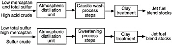
FIGURE 7-1 Two examples of chemical processing sequences used to produce jet fuel blend stocks.
to correction for tolerance of test methods. In many cases, refineries impose even more stringent internal requirements to ensure conformance statistically.
PRODUCTION METHODS AND THEIR EFFECT ON CHEMICAL COMPOSITION
Aviation turbine fuels are generally blended from straight-run kerosene fractions that have been subjected to some form of additional processing (Dukek, 1992). In some cases, jet fuel blending stocks are produced by hydrocracking heavier fractions. Fractions obtained from Tar Sand bitumen that have been coked and hydrotreated may also be used. All processing sequences employ distillation at some point. The initial boiling points are generally controlled to produce a product that meets flash-point requirements. The final boiling points are generally set to meet other requirements, such as freezing point, smoking point, or naphthalene content. Fuels with a lower freezing point, such as Jet A-1, require reducing the boiling point of the back end (the heavier boiling part of the fuel). Kerosene jet fuels generally contain hydrocarbon compounds from the C8/C9 carbon number range up to the C15/C16 range.
The sequence of processing and finishing steps used in the production of jet fuel blending stocks can vary widely depending on factors such as crude oil type, the complexity of the refinery, and concerns about specification limits. Detailed processing sequences are generally regarded as proprietary. However, processing sequences used to produce JP-5 have been surveyed for the U.S. Navy (Lieberman and Taylor, 1980; Varga, 1985). Examples of jet fuel processing sequences reported in this survey are discussed below.
Crude oils that produce kerosene fractions with low total sulfur can be chemically processed to reduce mercaptan sulfur (thiol) or organic acid content to meet specification requirements (Dukek, 1992; Taylor, 1992). Two examples of chemical processing sequences are shown in Figure 7-1. In the first example, a kerosene with a high acid content but low mercaptan sulfur and total sulfur is first treated with a caustic followed by water washing. Treating the fuel blending stock with sodium hydroxide converts the carboxylic acids, which are soluble in the hydrocarbon phase but not soluble in the
aqueous phase, to sodium carboxylic salts, which are insoluble in the hydrocarbon phase but soluble in the aqueous phase, where they are removed. Phenols and hydrogen sulfide can also be removed, but jet fuel range mercaptans and other sulfur compounds are left unconverted in the fuel. Clay treatment using attapulgus clay is employed to remove trace levels of sodium carboxylate salts left in the fuel and/or other trace polar compounds.
If the fuel blending stock contains excess odorous mercaptan sulfur compounds but acceptable total sulfur levels, it can be treated by a sweetening process (example 2). The sweetening process converts mercaptans into odor-free disulfides, which are left in the fuel. Older processes (e.g., Doctor or Bender sweetening) involve the oxidation of mercaptans using elemental sulfur, which can produce unwanted polysulfides. Newer processes (e.g., Merox) involve the catalytic oxidation of mercaptans with air over a fixed bed (Duval, 1968; Scheumann, 1956; Brown, 1973; Verachtert et al, 1985). The Merox oxidation step is preceded by a caustic wash to reduce the carboxylic acid level and followed by a water wash to remove carryover caustic and/or sodium carboxylate salts. A salt drier may be used to lower free-water levels prior to clay treatment.
Catalytic treatment in the presence of hydrogen can also be used to manufacture jet fuel blending stocks, for example, when higher sulfur levels mandate sulfur removal (Figure 7-2). Sulfur removal can involve either hydrotreating kerosene fractions or hydrocracking heavier fractions down to the boiling range of kerosene. The nature and magnitude of specific changes in compounds is a function of the type of hydrotreating process and its operational severity (e.g., catalyst type, pressure, temperature, hydrogen consumption, and space velocity). Hydrotreating usually removes sulfur from compounds such as mercaptans, sulfides, disulfides, and condensed thiophenes, removes oxygen from compounds such as carboxylic acids, peroxides, and phenols and removes nitrogen from nitrogen compounds such as indoles, carbazoles, and quinolines. In the hydrotreating process, organically bound sulfur is converted to H2S, oxygen is converted to H2O, and nitrogen is converted to NH3. Non-heteroatom compounds are left in the fuel. Hydrotreating also removes olefins
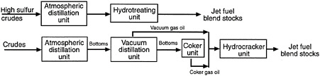
FIGURE 7-2 Two examples of catalytic treatments in the presence of hydrogen used to manufacture jet fuel blend stocks.
by adding hydrogen to olefin molecules, thus converting olefin to a saturated compound. Hydrocracking generally is done under high severity conditions. In addition to affecting boiling range conversion, hydrocracking also removes most heteroatoms and olefins (Mohantry et al, 1990).
ADDITIVES
Additives can have a significant impact on both the chemical composition and the chemical reactivity of jet fuel. Additives are strictly regulated by the specification to which the fuel is being manufactured. The approval process for a jet fuel additive is lengthy and involves extensive laboratory testing for material compatibility as well as testing for compatibility with other additives already approved for use in jet fuel. Specific approval by major engine and airframe manufacturers is also required.
In general, military fuels require more additives than civil fuels. Most of the Jet A civil fuel used in the U.S. contains no additives. Outside the U.S., civil jet fuel, Jet A-1, contains up to 5 ppm of an additive to increase electrical conductivity, which increases the rate of dissipation of any electrostatic charge that may have built up in the fuel as a result of microfiltration. The additive in use today, Stadis 450, is a mixture of polysulfones, polyamines, and dinonylnaphthyl sulfonic acid (Henry, 1975). Antioxidants may also be added (up to 24 ppm) to prevent the formation of hydroperoxide and gum from free radical reactions involving dissolved molecular oxygen, which is present in all fuel exposed to air. A number of different compounds from the family of sterically-hindered alkyl phenols are permitted or mandated, particularly in hydroprocessed jet fuel. ASTM D 1655 permits the use of N, N-diisopropylparaphenylene diamine, but hindered alkyl phenols are generally the antioxidant of choice in a clear product like jet fuel. A metal deactivator is permitted (up to 5.7 ppm) to chelate dissolved metals, such as copper. Chelation eliminates the deleterious catalytic effects of dissolved metals on fuel stability. ASTM D 1655 and Defense Standard 91/91 only allow one metal deactivator, N, N disalicylidene-1, 2-propane diamine.
A number of additives have been approved by the US Air Force and Navy for use in JP-8 and JP-5 as corrosion inhibitor and lubricity improving additives at concentrations ranging from 9 to 23 ppm. These additives are organic fatty acids, typically a C36 dicarboxylic acid. They were used initially to prevent rust pickup in the fuel from pipelines and tanks, but they were subsequently found to improve the lubricity properties of fuel that had been severely hydrotreated. Hydroprocessing tends to remove the trace impurity lubricity-enhancing compounds that are naturally present in the fuel. Although individual specifications vary, it is common to require a purchaser agreement for the use of a metal deactivator or corrosion inhibitor/lubricity improver in civil fuels.
Military aircraft fuel systems do not include fuel filter heaters, which are used in civil aircraft (Dukek, 1992). As a result, military fuels require up to 0.15 vol pct of a fuel system icing inhibitor. Diethylene glycol monomethyl ether is approved for this purpose, replacing ethylene glycol monomethyl ether, which is being phased out because of concerns about toxicity.
The U.S. Air Force is currently developing and introducing into service an improved thermal stability JP-8 jet fuel called JP-8+100, which contains proprietary detergent/dispersant additives in conjunction with the sterically-hindered phenolic antioxidant, 2,6 di-tertiary butyl-4-methyl phenol, and a metal deactivator.
CHEMICAL COMPOSITION AND REACTIVITY
The overwhelming majority of chemical compounds that make up jet fuel are hydrocarbons, including normal and branched paraffins, single and multi-ring cycloparaffins, single and multi-ring aromatics, hydroaromatics, and olefins. The relative proportions of hydrocarbon compound types can vary considerably, depending on the type of crude oil (see Table 7-2). Specifications limit the total of aromatics as measured by ASTM D 1319, "Hydrocarbon Types In Liquid Petroleum Products by Fluorescent Indicator Adsorption," to a maximum of 25.0 vol pct. This adsorption method reports alkyl benzenes, polycyclic aromatics, and aromatic olefins as aromatics. Naphthalenes are generally limited to 3.0 vol pct. Older specifications limited olefins by ASTM D 1319 to a maximum of 5.0 vol pct. Surveys indicate that the actual vol pct of olefins, in general, is much lower (Dickson, 1995).
Trace levels of heteroatom compounds are also present in jet fuel. Sulfur compounds are restricted to a maximum of 30 ppm from mercaptan (thiol) compounds and 3,000 ppm from all sulfur compounds. NIPER surveys indicate that the actual total sulfur levels are generally much lower (Dickson, 1995). In addition to thiols, sulfur compounds include sulfides, disulfides, and condensed thiophene-type compounds. Carboxylic acids (which are typically alkyl cyclo paraffinic acids) and phenols are also present and are limited by the acid number specification. A typical acid number specification limit of 0.015 mg KOH/g by ASTM D 3242 suggests an upper limit of approximately 60 ppm monocarboxylic acids in the jet fuel boiling range. Nitrogen compounds are not controlled by any specification, but analyses indicate that straight-run kerosenes typically have very low total nitrogen levels, e.g., less than 5 ppm. Nitrogen compounds are predominately alkyl indoles, carbazoles, pyridines, and quinolines (Snyder, 1970).
At ambient conditions, the majority of hydrocarbon compounds present in jet fuel are unreactive toward one another. Because jet fuels are normally saturated with air, there is always the potential for a reaction of the hydrocarbon/heteroatom mixture with the dissolved molecular oxygen. However, autooxidation reactions are typically very slow at ambient temperatures because jet fuels normally contain either natural or added inhibitors and in addition do not contain a strong initiation source for free radicals. Thus, under normal circumstances, jet fuel is by and large chemically unreactive at ambient conditions. However, the fuel can undergo autooxidative thermal stability-type reactions leading to the formation of deleterious surface deposits as the fuel is exposed to higher aircraft and engine temperatures as it is being delivered to the combustor (Taylor, 1992). Hereroatom compounds also tend to be more susceptible to thermal stability autooxidation reactions than hydrocarbons.
Trace impurities and additive compounds can potentially be reactive, although such occurrences are rare. For example, naturally occurring acids or acids present in some additives, such as corrosion inhibitors, have been known to become involved in acid-base reactions to form an adduct or reactions with metal cations to form soaps (carboxylic acid salts), which can have surfactant properties (Hazlett et al, 1991, 1993).
TABLE 7-2 Variations in Kerosene Hydrocarbon Compounds
|
Hydrocarbon Typea |
Variations in 150/280°C Kerosenes |
|
Paraffins Normal and branched paraffins |
10–65 % |
|
Cycloparaffins Single-ring cycloparaffins Multi-ring cycloparaffins |
10–35 % 5–35 % |
|
Aromatics Single-ring aromatics Multi-ring aromatics |
12–20 % 1–3 % |
|
Olefins |
0.5–5.0 % |
|
a By mass spectroscopy except for olefins which are by fluorescence indicator adsorption |
|

FIGURE 7-3 Typical aviation fuel distribution system.
TRANSPORTATION AND STORAGE
The shipment of jet fuel from the refinery to an intermediate terminal to airport storage facility can involve pipelines, tankers, barges, railcars, and/or trucks. In the U.S., pipeline shipments often involve common carriers, fungible pipelines where fuel from multiple shippers is commingled. Fueling planes at larger airports generally involves using an airport hydrant system or a servicer (Waite, 1989; ATA, 1986).
This complex storage and delivery system (illustrated in Figure 7-3) is designed to eliminate or control excess free water (i.e., water suspended in the fuel above the fuel saturation point), particulates such as rust and dirt, microbial contamination, and contamination from other products and their additives. A highly redundant system is employed with a number of different approaches that reduce fuel contaminants.
Controlled tank settling to remove water and particulates involves quarantining the tank, removing settled water and dirt from the bottom of the tank, and withdrawing clean fuel from the top of the tank via a floating suction take-off. Filters can also be used to remove particulates. Units called filter/separators, which combine the functions of filtration to remove dirt, coalescence to remove excess water, and a hydrophobic barrier or separator that rejects any free water in the effluent fuel are also used.
In addition to controlled tank settling and filter/separators, water-adsorbing media elements (called monitors) are often employed for filtration into and out of airport storage and as the final step before the fuel is loaded into an aircraft. Monitors stop fuel flow in the presence of excess water and filter out dirt. Clay treaters are also employed in the distribution system to remove surfactants, particularly in the U.S. where a large amount of jet fuel is shipped through multi-product pipelines. Surfactants can stabilize water droplets against natural settling and can also disarm coalescers. Removing water from the distribution system is the most effective way of preventing microbial contamination in jet fuel (Swift, 1988). Because of the importance of the distribution system for ensuring that clean, dry, uncontaminated fuel is loaded into aircraft, the effects of any new fuel additive on the integrity of the distribution system must be considered.
REFERENCES
ATA (Air Transport Association of America). 1986. Specification for Airport Fuel Inspection and Testing No. 103. Washington, D.C.: ATA.
Brown, K.M. 1973. Treating jet fuel to meet specs. Hydrocarbon Processing 52(2):69–74.
Campbell, P.P., and D.P. Osterhout. 1967. Proceedings of Symposium on Jet Fuel held June 29, 1967, in Boston, Massachusetts. Philadelphia: ASTM, Committee D-2 Petroleum Products and Lubricants, Technical Division J on Aviation Fuels.
Dickson, C.L., and G.P. Sturm. 1995. Aviation Turbine Fuels 1994. Bartlesville, Oklahoma: National Institute for Petroleum and Energy Research, Department of Energy.
Dukek, W.G. 1992. Aviation and other gas turbine fuels. Kirk-Othmer Encyclopedia of Chemical Technology (4th ed.), vol. 3, p. 788, Mary Howe-Grant, ed. New York: John Wiley & Sons.
Dukek, W.G., and K.H. Strauss, eds. 1979. Factors in Using Kerosene Jet Fuel of Reduced Flash Point: A Symposium. ASTM Special Technical Publication 688. Proceedings from conference held on December 3–8, 1977 in Dallas, Texas. Philadelphia: ASTM.
Duval, C.A.. 1961. Treating and sweetening. Pp. 164–195 in Advances in Petroleum Chemistry and Refining, vol. 4, J. J. McKetta, Jr., ed. New York: Interscience.
Dyroff, G.U. (ed.). 1993. Manual on Significance of Test for Petroleum Products (6th ed.). Philadelphia: ASTM.
Hazlett, R.N., E.J. Beal, M.D. Klinkhammer, and J.A. Schreifels. 1993. Comparison of stability results for distillate fuels exposed to different stress regimes. Energy and Fuels 7(1):127–132.
Hazlett, R.N., J.A. Schreifels, W.M. Stalich, R.E. Morris, and G.W. Mushrush. 1991. Distillate fuel insolubles: Formation conditions and characterization. Energy and Fuels 5(2):269–273.
Henry, C. P. 1975. Composition of Olefin-Sulfur Dioxide Copolymers and Polyamines as Antistatic Additives for Hydrocarbon Fuels. U.S. Patent No. 3,917,466.
Lieberman, M., and W. F. Taylor. 1980. Effect of Refining Variables on the Properties and Composition of JP-5. Final Report prepared for Naval Air Propulsion Center under contract no. N00140-78-C-1491. Linden, N.J.: Exxon Research and Engineering Company, Products Research Division .
Martel, C.R. 1987. Military Jet Fuels, 1944–1987. Contract No. AFWAL-TR-87-2062. Dayton, Ohio: Air Force Aero-propulsion Laboratory.
Mohanty, S., D. Kunzru, and D.N. Saraf. 1990. Hydrocracking: A review. Fuel 69(12):1467–1473.
Scheumann, W.W. 1956. Chemical and hydrogen treating. Petroleum Processing 11(April):53–57.
Smith, M. 1970. Aviation Fuels. Henley-on-Thames, Oxfordshire, U.K.: G.T. Foules & Co., Ltd.
Snyder, L.R. 1970. Petroleum nitrogen compounds and oxygen compounds. Accounts Chemical Research 3(9):290–299.
Swift, S.T. 1988. Identification and control of microbial growth in fuel handling systems. Pp. 15–26 in Distillate Fuel: Contamination, Storage and Handling, H.L. Chesneau and M.M. Dorris, eds. ASTM Special Technical Publication No. 1005. Philadelphia: ASTM.
Taylor, W.F. 1988. Fuels: The Next 50 Years. Exxon Air World 40(3):29.
Taylor, W.F. 1992. Effect of manufacturing processes on aviation turbine fuel thermal stability. Pp. 81–89 in Aviation Fuel: Thermal Stability Requirements, ASTM Special Technical Report No. 1138, Kirklin, P.W. and P. David, eds. Proceedings from conference held on June 26, 1991, in Toronto, Canada. Philadelphia: ASTM.
Varga, G.M., M. Lieberman, and A.J. Avella. 1985. The Effects of Crude Oil and Processing on JP-5 Composition and Properties. NAPC-PE-121C. Contract No. N00140-81-C-9601. Trenton, N.J.: Naval Air Propulsion Center.
Verachtert, T.A., J.R. Salazar, and B.E. Staehle. 1985. Merox Catalyst Innovation Solves Difficult Kerosene Treating Problems. Paper presented at National Petroleum Refiners Annual Meeting, San Antonio, Texas, March 24, 1985.
Waite, R., ed. 1989. Manual of Aviation Fuel Quality Control Procedures (MNL5). Philadelphia: ASTM.
8
Concepts for Safe-Fuel Technology
Bernard R. Wright
Southwest Research Institute
ABSTRACT
Researchers in the field of fuel safety have been on a quest to find replacements for halon and to develop new safety systems for protection against the ignition and burning of fuel in aircraft accidents. Recommended halon replacements have been announced for commercialization. New and undeveloped technologies include surface enhancement, low volatility, and self-activating powder extinguishment. These technologies may be used individually or may be synergistically combined via micro-encapsulation or specific system applications.
INTRODUCTION
The Montreal Protocol and the U.S. Clean Air Act stopped the production of halon at the end of 1993 because of stratospheric ozone depletion. Regulations governing the production and use of halon came about as a result of scientific assessments conducted under the auspices of the World Meteorological Organization (WMO) and the United Nations Environment Programme. The Scientific Assessment of Ozone Depletion is a collection of scientific reports and a history of those reports in relation to the international policy process (WMO, 1994).
The new regulations created a need for substitute agents that could be used for fire suppression and explosives protection. To meet the new standards, researchers in the field of fuel safety have been on a quest to find new safety systems that will protect against the ignition and burning of propulsion fuel. Previous studies were based on decreasing the flammability and ignition potential of fuel on board the aircraft. The idea was to modify the fuel so it would not sustain a fire. However, fuel treatments to increase fire safety are costly and add weight to the aircraft. In addition, decreasing the flammability or ignition potential of fuel may interfere with the fuel's ability to perform regular operations.
In this paper, new and unproven technologies for fuel protection will be described. These include substances that (1) are consumed with the fuel, (2) are mixed with fuel after an incident, and (3) suppress external fire. Various types of protective agents and fire suppressant agents are also described as replacements or alternatives. These include (1) surface enhancement agents, (2) low volatility agents, and (3) combined technologies, such as micro-encapsulation. The concepts presented in this paper are applicable to fuel itself and to fuel fires, such as fuel fires immediately following survivable air crashes.
BACKGROUND
Previous Safe-Fuel Technologies
Safe-fuel technologies have been developed and implemented with varying degrees of success. Some are already in use, including fuels and hydraulic fluids with improved safety properties. Volatile JP-4 fuel has been replaced by JP-8 fuel (Jet-A/A1), which has a flash point temperature above 100°F so that flame speed is reduced from 12 feet to 1 foot per second. A ''fire-resistant-fuel," comprised of fuel, water, and a solubilizing surfactant, has also been developed and patented.
A number of inerting agents and systems have been tested. The U.S. Army mixed halon with fuel for tank propulsion but could not use it because of the caustic/toxic products of combustion. Inerting of the ullage (empty space) in fuel tanks has been implemented. Halon is now used in F-16 aircraft, and nitrogen is used in the Apache helicopter and C-5A aircraft. The on-board inert gas generator (OBIGGS), which has a membrane to separate nitrogen from air, has also been developed and is used in some aircraft. The use of OBIGGS allowed the fuel tank oxygen concentration to be maintained at approximately 9 vol pct, which is too low to ignite. Foams in aircraft fuel tanks are used by the U.S. Air Force. A coannular fuel tank, with an inner space containing fuel and an outer space containing halon, has been demonstrated using halon 2402 but has not been implemented.
A less vulnerable fuel has been developed using a high molecular weight polymer as an antimisting agent. This approach paralleled a Federal Aviation Administration (FAA) project that incorporated an antimisting agent with a shear thickening mechanism. Antimisting kerosene (AMK) was
developed to mitigate fuel misting thereby decreasing fuel flammability and ignition, but the fuel was not ready for propulsion combustion and had to be processed before injection. When AMK was tested at full scale, it did not prove to be cost/performance effective.
Low expansion foam has been used to protect against fires in spilled liquid fuel (Class B) around the outside of the aircraft. The foam is a liquid at standard temperature and pressure and can therefore be projected to an aircraft's critical distance. Foam, which is primarily water, contains surfactants that isolate the fuel from air so that a flammable mixture of fuel and air is prevented. In other words, the lower flammable limit is not reached because of the layer of foam on the fuel surface. Another approach is using dry chemicals around an aircraft to provide for rapid knockdown of fire.
A good deal of progress has been made toward reducing flammability in aircraft interiors. New materials have significantly reduced flame speeds and smoke generation, as well as retardants and intumescent coatings. New exterior materials have been tested and appropriate standards for fire protection have been defined.
Halon and Halon Replacements
When selecting a substance for protecting against fuel fires, the first requirement is that the agent have the desirable physical-chemical characteristics. Halon 1301 has been the primary agent for fire protection on board an aircraft because (1) it is an effective fire suppressant (through the chemical action of the bromine atom, which acts as a catalytic fire chain breaker); (2) it can be stored as compressed liquid (small volume); and (3) it can flood (in gaseous form) the engine nacelles and cargo compartments.
The initiating study to find a halon replacement for the U.S. Air Force (USAF) was performed by Zallen International Associates (ZIA) (Zallen, 1992). A list of several hundred chemical agents was narrowed down to 12 potential candidates that met the criteria for a clean and effective replacement for halon 1301 fire extinguishing systems in aircraft (Bennett, 1992). Comparative analyses were performed on their physical properties and environmental parameters including boiling point, ozone depletion potential, toxicity, and fire suppression effectiveness.
Iodotrifluoromethane (CF3I) was identified in the initial study as the only halocarbon containing iodine that had a sufficiently low boiling point, -23°C (CHF2I has a boiling point of +22°C, and C2F5 I has a boiling point of +12°C). Because CF3I was the only agent (Purdue University, 1950) with fire suppression effectiveness close to halon 1301 (6.8 percent suppression agent concentration for CF 3I; 6.1 percent for halon 1301 [CF3Br]) there was a great deal of interest in investigating the environmental and toxicological characteristics of CF3I data. The Purdue University study of 1950 also demonstrated that several agents were even more effective fire suppressants than halon 1301, namely C2F4I2 (5.0 percent), C2F5I (5.3 percent), and C2H5I (5.6 percent). One agent, which was proprietary at the time, can now be identified as HFC-236fa (C3H2F6). The other agents investigated had boiling points that were too high for conventional total flooding, were not efficient fire suppressants, or were too toxic. Effective agents with higher boiling points were considered for streaming, or misting, applications.
The potential halon 1301 replacements were tested at laboratory scale at the National Institute of Standards and Technology (NIST, 1994), at intermediate scale by ZIA at Southwest Research Institute (Zallen, 1994), and at large scale by Wright Laboratory of Wright-Patterson Air Force Base. These investigations led to compatible conclusions, and the recommended agents (with trade names) have been announced for commercialization in the Significant New Alternatives Policy (SNAP) of the Environmental Protection Agency (EPA).
DEFINING THE PROBLEM
Post-crash fires cause about 40 percent of the fatalities in survivable incidents and are caused by uncontrolled fuel leaks ignited by sparks, hot surfaces, or fire elsewhere. In the critical period following a survivable crash, before ground crews arrive and gain control, immediate protection is needed against external fuel fires. The critical area around the aircraft is defined as the area beyond which heat from a fire does not affect the aircraft.
Fire-safe fuel technologies must be discussed in specific contexts. The specific scenario for this discussion is a survivable aircraft crash. In this scenario, fuel near the aircraft at rest is the major threat to survivors. Fuel spilled during such a crash is not of specific concern because the aircraft is not technically involved with fuel left behind, i.e., fuel beyond the critical distance.
The spilled pool of fuel near the aircraft can ignite and burn. The fuel mist near the aircraft is even more easily ignited than the fuel pool. Although the fuel mist is not a sustained hazard, it is a strong ignition hazard. However, it is not necessary to protect all of the fuel carried aboard the aircraft. Only the fuel that ends up within the critical distance from the crashed aircraft is a sustained hazard. It would therefore be efficient to treat the spilled pool of fuel and, specifically, the surface of the pool.
Although the spilled pool of fuel if the greatest danger, other fire hazards must be taken into account. These include the danger of pressurized fuel being sprayed/atomized, the danger of ignition of flammable fluids in storage tanks and delivery lines, and the danger of ignition of other flammable substances, such as cargo, oxygen, metals, and hydraulic components.
Once the general potential hazards have been analyzed, fuel systems should be characterized to define specific hazard scenarios. Accident investigation reports and fuel systems configurations are typical ways of defining specific hazard scenarios, which can be used to hypothesize various safety concepts.
Many pragmatic concerns must be addressed when evaluating potential safety concepts. After the basic performance of an agent or concept has been hypothesized and tested, the next step is analysis of a practical system's performance. Initial analyses may be done of size, weight, and costs. Cost analyses must include the number of applications and whether the system is new or retrofitted, because these factors determine how the benefits are attributed. Logistical analyses include geographic locations and transportation requirements (e.g., approval requirements in the United States, as opposed to requirements in Europe, for pressure vessels). Reliability studies include analyses of specific parts and repair time and maintenance.
Once initial evaluations have been established, program plans for the safety concept must be developed. For new or undeveloped concepts, full testing plans must be developed, including tests for toxicity and potential exposure. Options and combinations of concepts should also be evaluated. For example, a fire prevention agent might be mixed with fuel by coannular fuel/agent tanks or by honeycomb compartmented agents and fuels. A fire prevention agent that may perform well in one application might not perform well in another. Perfluorohexane, for example, is a good fire suppressant in general and has no ozone depletion potential (it does have a long atmospheric lifetime). However, mixing liquid perfluorohexane with liquid fuel has a low coefficient of mass transport from liquid to gas phase and results in poor protection against open-pool ignition and spreading flames (Naegeli et al., 1993).
NEW AND UNDEVELOPED SAFE-FUEL TECHNOLOGIES
The following is a discussion of three technologies for making fuels safer: surface enhancement, low volatility technology, and self-activating powder extinguishment. Specific agent compositions are not presented, but recent literature abounds with descriptions of halon replacements and alternatives.
Surface Enhancement Technology
Halon replacements with reasonably good weight are commercially available. The effectiveness of replacements has been defined in classic tests, such as total flooding and streaming capabilities in classic halon test fire scenarios, e.g., computer room fires, Army tank engine compartment fires, USAF engine nacelle and dry bay fires, and Navy machine room fires. No halon replacement has all of the good characteristics of halon 1301. In order to get the same protection for similar weight and cost, the physical and chemical characteristics of less desirable agents must be enhanced.
Because the fuel surface provides the vapor for a fire, enhancing the effectiveness of the agent at the fuel surface will enhance agent efficiency and improve its fire prevention potential. So, one idea is to provide surface-enhancement for halon replacements or alternatives. Surfactant mixtures can be used to improve the distribution of the agent at the fuel surface. The mixture must, of course, be environmentally compliant and stable. Surfactant mixtures have been used with water, which is the basis for contiguous foam. Although in principle a water/surfactant mixture works, it is neither weight nor temperature effective in many applications. But it should be possible to use surface enhancement to improve the performance of halon replacements.
Low Volatility Technology
The environmental problems associated with effective halons is well known. Bromine and chlorine function well against fire, but their high volatility leads to release into the atmosphere. One approach to mitigate this danger was to use hydrochlorofluorocarbons (HCFCs) whereby a substituted hydrogen atom decreases the stability of the halon molecule in the atmosphere/troposphere on its way to the stratosphere. This hydrogen substitution is also the basis of hydrofluorocarbons (HFCs). However, in general the hydrogen atom substitution implies more reactivity, which also implies more toxicity.
Halon replacement studies have so far concentrated on paraffinic chemicals because the reactivity of olefinic chemicals is known and their toxicity suspect. The boiling points of higher molecular weight chemicals are too high and the vapor pressures too low for halon replacement, but larger molecules do have more bonds (i.e., degrees of freedom) to absorb ignition or fire energy. Some general (not absolute) rules follow: the boiling point of an agent rises with molecular weight; using heavier halogen atoms raises the boiling point; hydrogen substitution raises the boiling point; hydrogen substitution increases reactivity and potential toxicity; fluorine atoms provide stability; and vapor pressure is inversely proportional to the boiling point. These generalities indicate why so few chemicals can readily be identified for replacement of volatile halon 1301.
Using lower volatility agents in fire prevention applications may improve effectiveness. Highly volatile agents have inherent deficiencies in that: the agent can vaporize en route to the fire; the agent may not be concentrated near the fuel surface; and the concomitant large vapor cloud is an environ
mental hazard, may be toxic, and may not increase fire prevention. Low volatility technology (LVT) works by deriving a volatile, efficient fire suppressant from pyrolysis of the initially nonvolatile agent. LVT agents would be effective because no agent would be lost by evaporation along the delivery trajectory, the agent is deliverable because of its low volatility, harmful emissions would be minimized, and agent/surfactant control of the fuel surface would be increased. The agent would be concentrated where the fire was initiated with heat from the fire and hot surfaces releasing the fire prevention chemical.
Self-Activating Powder Extinguishment Technology
Dry chemical powders have been used as fire fighting agents for many years. It is known that fine particles, on the order of ten micrometers, are more effective fire extinguishers on a mass basis than larger particles, on the order of one-hundred micrometers. Large particle powders are still used, however, for two primary reasons. First, grinding powder to fine particulates, which can cake in storage, is not cost effective. Second, the short throwing (delivery) distance of fine particulate powder makes it difficult to get the agent where it is needed.
Three mechanisms principally account for the fire prevention performance of dry chemicals. The first is the thermal cooling from the intrinsic thermal mass of the cold material; this is augmented by endothermic decomposition reactions. The second mechanism is chemical action, whereby flame propagating species, such as hydrogen and hydroxyl radicals, may recombine either heterogeneously on the surface of the particles or homogeneously as a result of gas phase reactions catalyzed by alkali metal atoms. Third, the water and carbon dioxide produced in the reactions act as local oxygen diluents or inertants. Two of these essential mechanisms are surface effects, so a greater surface area per unit mass of fine particulate powder speeds the mechanisms for better fire prevention.
Comparative tests have shown that fine dry powder is more effective at extinguishing fires than any of the new halon replacements. But, there are some problems: limitations on the fineness of the powder that can be manufactured at reasonable cost; difficulties preventing the agglomeration and coagulation of fine powders in storage; and problems of effectively discharging particles with low momentum.
The use of fine particle powders for fire prevention is currently based on propellant-generated solid aerosols. Pyrotechnic compositions, comprising a potassium-based oxidant and an organic binder, can generate a fire extinguishing aerosol. High reaction temperatures mean that the salts produced are initially gaseous and that the particulates produced by condensation from the vapor phase are extremely fine. Experiments on devices for total flood extinguishment show that suppression by fine particle powder requires significantly lower mass concentrations than halon.
Pyrotechnically-generated aerosols (PGAs) use potassium-based oxidizers to maximize the known fire suppression capability of potassium salt. The fuel may consist of a binder and a metal powder as co-fuels that generate enough heat to vaporize potassium-based fire prevention additives. The oxidizer/fuel ratio is designed to generate the product quickly, absorb energy, and result in optimal composition. PGA aerosol properties give them excellent three dimensional distribution and long term suspension. They have zero ozone depleting potential, low toxicity, and show significant weight reductions compared to halon.
TECHNOLOGY COMBINATIONS
Known effective fire suppressing agents are limited in number and type. There might therefore be some benefit in combining individual technologies, not by the simultaneous use of two types of prevention, but rather by some synergistic combination of the scientific bases that make certain materials work.
Micro-encapsulation
In the development of fire resistant fuel wherein 2 to 3 percent water was used in diesel fuel, two things have been shown. First, although evaporative cooling effects are significant, they are not responsible for the self-extinguishing properties of aqueous diesel fuel. Second, when the heat transfer in the liquid surface, which causes preheating of the surface ahead of the flame, is reduced, it generates a water vapor blanket for self-extinguishment (Weatherford and Naegeli, 1984).
One way to both increase the amount of fire suppressant at the fuel surface and lower the volatility of a high volatility agent is micro-encapsulation. Micro-encapsulation would reduce vapor loss from a high volatility agent until the agent is needed. The contents of the microcapsule could include any number of fire suppressants. By making them lightweight for flotation, the microcapsules could be concentrated at the fuel surface for synergistically increasing efficiency. Heavier capsules could be developed for situations where mixing is required.
A urea-based capsule could potentially both release the contained substance and provide fire protection. The outer shell of the capsule might be a dry chemical powder, for example, Monnex™ powder, which provides rapid fire knock-down by cracking apart to form smaller, more efficient particles.
System Applications
There are many different ways to use new agents for fuel fire prevention or suppression. Insoluble compounds with fire
protection capacity may be added to fuel for protection in the fuel tank, but be physically separated from the fuel before combustion takes place. The stability of the suspension and the chemical composition of the compounds need to be considered in these applications.
Inerting agents which are kept separate from the fuel may be released in a number of ways. The fuel and inertant could be separated by a honeycomb in an intrinsic system. The inertant would thereby be released if the fuel tank ruptured. In a separate system, the inertant could be kept in frangible tubes in the fuel, and released by fire or rupture.
Fire suppressing agents could also be used as fuel additives. Mixtures of salts (acetate, citrate, carbonate) with water have long been used to protect cooking facilities. New investigations (Finnerty et al., 1996) have shown that aqueous solutions of potassium lactate or potassium acetate extinguish fuel fires much better than water alone. The improvement can be attributed to the release of solid salts upon evaporation of the water in the fire zone. This new understanding could be used for fuel fire-safety.
REFERENCES
Bennett, Michael. 1992. Halon replacement for aviation systems. Pp. 668–669 in Proceedings of the 1992 International CFC and Halon Alternatives Conference: Stratospheric Ozone Protection for the 90s held September 29 to October 1, 1992 at the Washington Hilton, Washington, D.C. Frederick, Md.: International CFC and Halon Alternatives Conference, 1992.
Finnerty, A.E., R.L. McGill, and W.A. Slack. 1996. Water-Based Halon Replacement Sprays. ARL-TR-1138. Aberdeen Proving Ground, Md.: Army Research Laboratory.
Naegeli, D.W., B.R. Wright, and D.M. Zallen. 1993. A Study of Aircraft Post-Crash Fuel Fire Mitigation. BFLRF Interim Report No. 292. San Antonio, Texas: Belvoir Fuels and Lubricants Research Facility, Southwest Research Institute.
National Institute of Standards and Technology (NIST). 1994. Evaluation of Alternative In-Flight Fire Suppressants for Full-Scale Testing in Simulated Aircraft Engine Nacelles and Dry Bays. Special Publication 861. Washington, D.C.: U.S. Government Printing Office.
Purdue University. 1950. Fire Extinguishing Agents. AD 654-322. Lafayette, Ind.: Department of Chemistry and Research Foundation, Purdue University.
Weatherford, W.D., and D.W. Naegeli. 1984. Study of pool burning self-extinguishment mechanisms in aqueous diesel fuel microemulsions. Journal of Dispersion Science and Technology 5(2):159–177.
World Meteorological Organization (WMO). 1994. Executive Summary: Scientific Assessment of Ozone Depletion. Global Ozone Research and Monitoring Project Report No. 37. Geneva, Switzerland: WMO.
Zallen, D.M. 1992. Halon Replacements Study. ZIA-92-001. Wright-Patterson Air Force Base, Ohio: Aeronautical Systems Division, U.S. Air Force Material Command.
Zallen, D.M. 1994. Halon Replacements Study. ZIA-94-0100. Wright-Patterson Air Force Base, Ohio: Aeronautical Systems Division, U.S. Air Force Material Command.


