
Appendix A
Synopses of Air Force Aging Aircraft Structural Histories
This appendix provides a brief synopsis of the structural history for each of the Air Force's aging aircraft listed in Table 3-1. Also included are brief summaries of recent structural problems encountered on aircraft that have been reported to the committee by representatives of the system program directors, the Aeronautical Systems Center's engineering and technical management organization (ASC/EN), and the aircraft manufacturers.
AIR MOBILITY COMMAND AIRLIFTER AND TANKER AIRCRAFT
C/KC-135
The Air Force acquired the KC-135 tanker aircraft to replace the KC-97 to fulfill the need to refuel the B-52 bomber force. Boeing developed the prototype of this aircraft, designated the 367-80 or simply the Dash-80, with their own funds. The first flight of the Dash-80 took place in July 1954. From this aircraft, Boeing developed the KC-135, as well as the 707 and 720 commercial jet transport aircraft. The Air Force ordered limited production of the KC-135 in August 1954, and the first flight occurred in August 1956. Production continued until 1965, with a total of 820 aircraft manufactured. Thirty-seven different designations of the -135 aircraft have existed in the Air Force inventory. The active KC-135 force is still in excess of 600 aircraft with more than 550 of them in the tanker force. As of October 1994, the average use was 13,536 flight hours or 3,153 flights for the KC-135 and 28,361 flight hours and 3,108 flights for the RC-135.
To minimize structural weight and thus maximize payload capability, the Air Force elected to use 7178-T6 aluminum in the lower wing skins as well as in other locations in the aircraft along with 7075-T6 aluminum. The commercial 707 used 2024-T3 aluminum in the lower wing skins at about two-thirds the stress level. Other structural differences between the -135 and the 707 are found in the fuselage structure. For example, sections of the -135 lower fuselage (below the floor) that contain body fuel cells are not pressurized. Also, the -135 fuselage does not contain tear straps and shear ties between the fuselage frames and skins. Although the 707 had a design life goal of 20,000 flights or 60,000 flight hours, the Air Force did not specify a design service life goal for the KC-135.
In 1962 the Air Force decided to perform a full-scale fatigue test of the KC-135 to quantify its expected life. The test resulted in a failure of the wing at 55,000 simulated flight hours. A tear-down inspection of the failed wing revealed several hundred smaller cracks. From this test the Air Force estimated that the safe life of the wing was about 13,000 flight hours. However, by the late 1960s it became apparent that the wings were cracking earlier than expected and that the 13,000 hours, even if correct, probably was not sufficient to cover the projected future use of the aircraft. As a result, a second more realistic full-scale fatigue test was performed in 1972. This test eliminated the load excursions to 90 percent of limit load that were applied every 200 flights in the 1962 test. These load excursions were intended leave marker bands on fatigue crack surfaces to assist post-test evaluation, but actually artificially prolonged the test life by retarding the crack growth. More wing cracking occurred in the 1972 test than in the 1962 test, and complete failure occurred at 43,200 simulated flight hours. The existence of many small cracks early in the fatigue test raised a concern about the possibility of widespread fatigue damage (WFD) in service aircraft. Adding to the concern was the very small critical crack sizes in the 7178-T6 wing skin and the fact that by the mid-1970s there already had been a number of cases of unstable crack propagation and panel failures in service aircraft. Although the wing was fail-safe for these failures, the concern was that this fail-safety would be lost if WFD was present. Boeing performed tear-down inspections of six wings removed from service to determine the actual state of fatigue cracking in the wings of service aircraft. In 1977 the Air Force formed a blue ribbon panel to look at this problem. The panel concluded that the onset of WFD was occurring between 8,000 and 9,000 flight hours and recommended that (1) the lower surfaces of the wings be redesigned and replaced using the 2024-T3 aluminum used on the 707 and (2) flight restrictions be imposed on all aircraft that had already reached 8,500 flight hours. This led to a modification program to replace the center and inner lower surfaces of the wing out to wing station 733 production joint (i.e., just outside the outboard engines). The Air Force elected not to modify the 7178-T6 outer wing panels, but
instead decided to cold work the fastener holes to enhance their resistance to fatigue cracking.
In 1977 the Air Force initiated a durability and damage tolerance assessment (DADTA) of the KC-135 with primary emphasis on the fuselage and empennage because the earlier modification had removed much of the concern about the wings. From this assessment, combined with an evaluation of the 1972 fatigue test results, it was estimated that, with the defined inspections and modifications, the aircraft could be flown safely well into the twenty-first century (i.e., it was estimated that the economical service life would extend to or beyond 2040 with the estimated utilization rates).
During the 1980s the reengine of the KC-135 aircraft was initiated to increase the aircraft's fuel off-load capability and reduce the noise levels. The old J57 engines were replaced with new CFM-56 engines on the active Air Force tankers (then redesignated KC-135R) and used JT-3D fan engines from retired 707 commercial aircraft on the Air National Guard tankers (then redesignated KC-135E). These engine modifications had little or no effect on the aircraft's structural integrity, even though some structural modifications were required.
Concern about structural deterioration due to corrosion led to a tear-down inspection of a retired KC-135 aircraft in 1991 by the Oklahoma City Air Logistics Center (ALC). This aircraft had spent 29 years at Mildenhall Air Base in the United Kingdom, which has a very corrosive environment. This inspection, and continuing corrosion investigations, provided considerable insight into the extent of corrosion and where to look, particularly the hidden areas. It also served as a testbed for evaluating various nondestructive inspection techniques. Corrosion and stress corrosion cracking (SCC) remain the primary structural issues concerning the KC-135. Specific concerns were that the life of the airframe would not meet the 2040 goal that was estimated by the 1977 DADTA because corrosion would accelerate the onset of WFD in the fuselage or empennage or make some of the calculated inspection intervals unconservative.
In 1995 the C/KC-135 system program director chartered the C/KC-135 aging aircraft integrated product team, known as Coral Reach, to develop an aircraft sustainment master plan, which defined a number of activities intended to enhance flight safety, reduce the cost per flying hour, and improve aircraft availability. In early 1996 this plan was reviewed by a blue ribbon panel consisting of representatives from the Air Force, NASA, and the FAA, with advisors from Boeing, the prime weapon system contractor. This panel concluded that from the available data it does not appear that there will be an onset of WFD in the fuselage, the empennage, or the previously modified lower wing surfaces until after 2040, assuming that the aircraft utilization rates and use remain as predicted. This conclusion was based partially on the results of tear-down inspections of fuselage panels removed from high-time 707/JSTARS aircraft. These panels were heavily corroded, but there was no evidence that this was causing early fatigue cracking. However, the panel acknowledged that there are differences between the 707 and KC-135 fuselage construction in some areas, and additional analytical investigations and inspections were needed to improve the estimates of the onset of WFD. Also, the panel expressed concern about the long-term effectiveness of the cold-worked fastener holes in the 7178-T6 aluminum lower surfaces of the outer wing (i.e., this stemmed from the fact that some small fatigue cracks had been reported in some outer wing fastener holes in one specific aircraft that had been inspected) and recommended several actions, including assessing the need to replace these lower wing surfaces and the station 733 joint closure rib that has had a lot of problems with corrosion and SCC. It is the committees understanding that the Air Force is now seriously considering this option. The 1996 blue ribbon panel also complimented Oklahoma City ALC on its maintenance program and emphasized the need to maintain aggressive efforts to prevent corrosion and SCC from becoming safety issues.
During the course of this study, the following specific corrosion and SCC problems were reported to the committee by a representative of the system program director:
-
corrosion between fuselage lap joints and spot-welded doubler layers
-
corrosion around fasteners in the 7178-T6 aluminum upper wing skins
-
corrosion between wing skins and spars
-
corrosion between bottom wing skin and main landing gear trunnion
-
corrosion between fuselage skin and steel doublers around pilot windows
-
SCC of large 7075-T6 aluminum forgings (fuselage station 620, 820, and 960)
-
corrosion and SCC of fuselage station 880 and 890 floor beams
-
corrosion and SCC of the wing station 733 closure rib
-
corrosion in the E model engine struts
C-141B
The C-141A was designed and manufactured by Lockheed (now Lockheed-Martin) as a long-range, heavy logistics transport aircraft. The primary materials in the aircraft are the 7000-series aluminum alloys heat treated to the T6 condition. A total of 285 aircraft were manufactured and delivered to the Air Force from January 1964 to February 1968. The original design life goal for the aircraft was 30,000 flight hours, and a full-scale fatigue test was performed to validate this design goal. In addition, the aircraft was designed to be fail-safe for a single-element failure (e.g., a single wing plank), which was then the standard for
commercial aircraft design. The Aircraft Structural Integrity Program (ASIP) also included an individual aircraft tracking program (IATP).
By 1974, after the aircraft had been in service for about 10 years, it was evident that the fuselage was volume limited for a number of logistics missions. A decision was made to add approximately 22 ft. to the length of the fuselage and to add in-flight refueling capability to the aircraft. However, before the Air Force was willing to expend the funds on this effort, it wanted to know if there was enough remaining life to justify the modifications. The Air Force's Aeronautical Systems Division (now Aeronautical Systems Center) recommended that an update of a 1975/1976 C-141A DADTA be performed to determine this justification and to define additional modification and inspection requirements. This assessment was performed in 1977 and early 1978 and concluded that the lower-bound economic service life was 45,000 hours of the then-current use spectrum (called the SLA-II spectrum). The aircraft fuselages were extended and the aircraft were redesignated as the C-141B.
By late 1992 the aircraft had reached an average of about 35,000 equivalent SLA-II spectrum hours, with some higher-time aircraft approaching the 45,000-hour economic service life estimate. Also, by then the aircraft had been experiencing many fatigue cracking and corrosion problems. Because of delays and uncertainty about the future of the C-17, which was to replace the C-141, Congress, in their FY93 authorization bill, directed the Secretary of the Air Force to convene a Scientific Advisory Board (SAB) committee to determine the technical feasibility of extending the service life of the C-141. This committee was convened early in 1993, held a series of meetings during the first half of that year, and released a final report in January 1994.
At the time of the SAB committee reviews there was increasing evidence of the onset of WFD in several different locations in the wings, corrosion and SCC in the upper surface of the center wing, fatigue cracking and SCC around the windshield, fatigue cracking in the stiffeners in the aft pressure door, SCC in the fuselage main frames, and some corrosion in the empennage.
Tear-down inspection of the wings from the service aircraft, which had about 45,000 equivalent SLA-II spectrum hours, showed evidence of WFD in the fuel drain holes (i.e., weep holes) in the integral risers in the lower surfaces of the wings. Methods to protect the structural safety until aircraft retirement or lower-surface replacement by inspections, hole cold working, and the use of bonded composite doublers were being investigated. Also, WFD had been found previously in the wing station 405 chordwise joint that connects the inner wing to the outer wing, and a modification consisting of a large doubler plate plus many local repairs and hole oversizings was already under way. Although the corrosion and SCC was a serious maintenance problem in the center wing box, the most serious concern from the standpoint of flight safety was the fatigue cracking that was occurring in the joggle area of the lower-surface side-of-body chordwise joint (wing station 77). At the time of the review, 72 aircraft had had their center wing boxes refurbished and this lower joint reinforced. The structural safety of the remainder of the aircraft was being protected by frequent close inspections until they could be modified or the aircraft retired. The final area of the wing that was a concern form the standpoint of WFD, and probably the most difficult in that there was no identified modification or repair short of lower-surface replacement, was the spanwise splices that connect the multiple wing panels together. During the 1977/1978 DADTA and again in a review in 1990, it had been predicted that the onset of WFD in these splices would occur at about 45,000 equivalent hours of the SLA-II spectrum. The tear-down inspection of the wings that had about 45,000 hours had revealed some cracking, but the inspections were not complete and no final judgment about the adequacy of the 45,000-hour limit was made by the SAB committee. None of the fuselage or empennage cracking and corrosion problems were considered to be life limiting by the SAB committee, and various modifications and repairs were under way. However, the SAB committee identified several areas of the aircraft where corrosion was causing major economic problems.
Since the 1993 SAB committee review the weep hole cracking problem was brought successfully under control through a combination of inspections, the use of bonded boron/epoxy doublers, and, where possible, cold working of holes. This took a concerted effort by the Air Force's Wright Laboratories, Warner-Robins ALC, and their supporting contractors. Also, the modifications to the wing station 405 splice were completed, and inspections, modifications, and repairs in the other areas of the aircraft continue to take place. With regard to the onset of WFD in the wing spanwise splices, there have been additional inspections in operational aircraft and more cracking has been found. Using these findings, Lockheed-Martin has performed a risk analysis and has concluded that the previous 45,000-hour estimate for the onset of WFD is unconservative. They now believe that 37,000 equivalent hours of SLA-II is a better estimate of the onset, causing concern over the fail-safety of all aircraft with a greater number of hours. The only alternative to grounding (or replacing the lower wing surface) is to protect the structural safety through frequent, careful, and very burdensome inspections of all highly-stressed fastener holes in the spanwise splices to detect and repair cracks before they reach critical size. This will require the inspection of over 6,000 fastener holes per aircraft every 120 days until the aircraft is retired. The C-141Bs are now in the process of being retired and replaced by the C-17, but as seen in Figure 2-4, they will not be completely phased out of the inventory for several more years. Until it is retired, the structural management of this force will continue to be a significant challenge.
C-5
Lockheed was awarded the contract for the C-5A airlifter in October 1965. The first flight was in June 1968, and by the end of 1970 thirty aircraft out of a total production buy of eighty-one had already flown and were delivered to the Military Airlift Command. All of the production aircraft had been delivered by May 1973. Full-scale static and fatigue testing that was conducted in 1971 revealed serious structural deficiencies (discussed below) that led to a major wing modification program called H-Mod. No changes or modifications were incorporated during production on any of the 81 aircraft because of the lateness of the testing1 and because of the type of contract that the government had with Lockheed (i.e., fixed price under a total package procurement concept). The Air Force authorized Lockheed to proceed with H-Mod in 1978, and by 1987 all surviving C-5As had been modified. Also, in 1982 the decision was made to have Lockheed build 50 C-5Bs, which incorporated the wing improvements included in the H-Mod. This program was completed in 1988. As of September 1996 there were a total of 126 C-5s (As and Bs) in the inventory. This included 81 in the active force, 32 in the Air Force Reserve, and 13 in the Air National Guard. The average age of the total C-5 force is 18 years; however, the average age of the A model is about 26 years. The flight-hour distributions for the C-5A and C-5B aircraft are shown in Figure A-1.
The C-5 structure is a multiple-load-path fail-safe design that is made predominately of 7000-series aluminum alloys. The wings consist of a center wing box, inner wing boxes, and outer wing boxes. The upper and lower surfaces of the boxes are made of shiplap planks fastened together by single rows of interference fit fasteners. The individual planks are machined from thick aluminum plate with integral spanwise stiffeners. The planks in the original C-5 wings were made from 7075-T6 aluminum, but in H-Mod they were changed to 7075-T73511. The original contract for the C-5 specified the maximum empty weight as a design requirement, but provided for the 30,000-hour design life as a noncontractual design goal. Thus, when difficulties were encountered in achieving the weight requirement, the contractor elected to reduce the thickness of the wing planks, which raised the operating stress levels in the wings. The resulting stress levels were significantly higher than the contractor had used previously in the design of the C-141 wings and they were much higher (e.g., 40 to 80 percent higher) than those used on any commercial transport aircraft. It was hoped that the adverse effect of these higher stresses on structural life would be offset by improved quality (i.e., lower stress concentration factors) and the beneficial effects of the interference-fit fasteners, and thus the design life goal would still be achieved. This did not turn out to be the case.
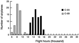
FIGURE A-1 C-5 flying hour distribution (through March 1996).
The first major structural difficulty occurred in the spring of 1971 when there was a tension failure of the lower surface of the wing at less than the design ultimate strength during the full-scale static test program. Next there was a series of local failure and cracking problems very early during full-scale fatigue testing. The three major problem areas were (1) the chordwise joints at wing station 120 that connect the inner wings to the center wing box, (2) the spar webs, and (3) the spanwise splices that connect the shiplap wing planks together. In fact, it appeared that the wings were in a state of WFD after less than one-third of a design lifetime of cyclic testing. At this point the Air Force and Lockheed jointly decided that an independent review team (IRT), consisting of government and industry aircraft structures experts from outside the C-5 program, should be formed to perform an indepth review of the C-5 structural design (with primary emphasis on the wings) and determine available solutions. This effort was conducted in 1972 and was one of the first DADTAs of Air Force aircraft.
Although the wings were designed to withstand the loss of a single wing plank without a complete wing failure, the IRT had two concerns about the fail-safe design. First, there was a concern that if a plank failed due to manufacturing damage (e.g., a rogue flaw) in a spanwise splice fastener hole, there was a high probability that the flaw would exist in two planks (i.e., due to the common fastener hole) and as a result there would be a two-plank failure that the wing could not sustain. Second, even if only one plank failed, the wing would not be fail-safe if the structure reached the point where there was WFD (i.e., there were many small cracks in the adjacent wing planks). Thus, the IRT determined safety limits for the C-5 wings based on slow crack growth from an assumed maximum probable initial manufacturing damage in a spanwise splice fastener hole and also by estimating the onset of WFD based on the fatigue test results. In addition, they developed and evaluated numerous potential near-and long-term solutions, including load alleviation options, several types of fastener changes, various local reinforcements, and redesign of major portions of the wings. The IRT recommended fuel
management and a load alleviation system to reduce the near-term fatigue damage rate and development of an essentially new, lower-stressed wing (i.e., plan H or H-Mod) for incorporation before reaching the estimated safety limit of the original wings. They recommended that the use of the aircraft then in operation be limited to 6,500 hours. This was based on the 1972 use spectrum (i.e., a 14-mission spectrum) and assumed that a passive load distribution system was implemented. This limit was based on safe crack growth from an initial manufacturing flaw in a spanwise splice fastener hole. The estimated time for onset of WFD was only slightly higher at about 8,000 hours of the same spectrum.
Following the IRT study, the ongoing C-5 program at Lockheed continued to evaluate the options, refine the H-Mod design, review the use of the operational aircraft, refine the damage tolerance calculations, and further evaluate the findings from the fatigue test articles. Also, Air Force Headquarters had asked the RAND Corporation to perform an airlift study, which included another independent look at the C-5 structures problem. There was considerable resistance against the Air Force immediately committing to a major modification program for the C-5A because of the costs involved, uncertainty over the extent of modifications that were really needed, and when it was needed, and the perception that Lockheed would be rewarded for fixing a problem that many felt was of their own making. In January 1975, the Air Force Aeronautical Systems Division (ASD) asked a committee of the SAB's Division Advisory Group to review the new data and results of the analyses and evaluations performed since the 1972 IRT and assess their potential impact on the need for H-Mod and recommendations for when it should be initiated.
By the time of the January 1975 review by the Division Advisory Group committee, the operational spectrum for the C-5A had been changed from the original 14-mission spectrum to a new spectrum called the ''representative mission profiles," or the RMP spectrum, so as to more nearly reflect the actual and planned aircraft use. Also, the tear-down inspection of the full-scale fatigue test wings had revealed more spar web cracking than had previously been thought to exist, and the damage tolerance analyses had been refined to include the effects of shear loading on crack growth rates. The additional spar web cracking indicated that new spar webs were likely required for H-Mod, rather than only repairs as had been previously thought. The net result of the changes in the spectrum and analysis method resulted in a predicted safety limit of 8,000 RMP hours based on slow crack growth from an assumed 0.05-in. initial manufacturing flaw in a spanwise splice fastener hole to critical size. It was also estimated that the onset of widespread fatigue cracking may be as high as 10,000 RMP hours. The Division Advisory Group committee reiterated the need for H-Mod and further recommended an active load distribution system rather than the passive system then in use. This would further increase the safety limit by about 10 percent.
The position taken by the RAND Corporation from their study was that the Lockheed and Air Force analyses were too conservative and that the onset of widespread fatigue cracking may be in the 12,000 to 15,000-RMP-hour range. Also, they were skeptical about the need for a modification as extensive as H-Mod and believed that it would outlast the rest of the aircraft. They further recommended information enhancement initiatives to better define the C-5's structural modification needs. The ASD agreed that there were uncertainties in the safety limit prediction and the estimate of the onset of WFD, but did not agree that they were overly conservative. ASD also supported the recommendation for information enhancement initiatives, specifically further residual strength analysis and tests, nondestructive evaluation (NDE) development, risk analysis, and a phased tear-down inspection of the wings from a high-time aircraft to determine if widespread cracking had initiated. These recommendations led to the 1977 Structural Information Enhancement Program (SIEP), which was, in effect, another DADTA of the C-5A wing structure.
As part of the 1977 SIEP effort, the slow crack growth safety limit was refined further, based on additional analyses and tests, to be 7,100 RMP hours compared with the 8,000-RMP-hour value at the time of the 1975 Division Advisory Group committee review. Also, as part of this SIEP effort, a wing that had been on an operational aircraft (Lockheed no. 68-0214) was torn down and inspected. This aircraft had accumulated about 6,700 RMP hours at the time of tear down. A total of 44,641 fastener holes were inspected, and 1,361 small cracks were detected. Of these, 931 were considered significant. Although initial manufacturing damage was noted in some holes, none was as large as was assumed in the safety limit calculation. On the other hand, the number of small cracks was more than anticipated. A risk assessment was performed to determine whether or not the C-5A wings would have lost their fail-safety given a single-plank failure from any cause (e.g., impact from an engine burst or gunfire), assuming that the crack population found in aircraft 68-0214 was representative of the other aircraft. The results of this analysis predicted that the failure probability was about 2 × 10⁻³ at the time the 7,100-RMP-hour safety limit is reached. Although this was higher than the 1 × 10 -4 that had been established previously as criteria for the onset of WFD, the Air Force group monitoring the SIEP activities did not recommend a reduction in the 7,100-hour safety limit and scheduled time for H-Mod. However, an enhanced special inspection program was recommended on each aircraft until H-Mod was accomplished. During the 1980s the H-Mod program proceeded relatively free from further disruption until it was completed in 1987.2
In November 1996 this committee received a briefing from a representative from the San Antonio ALC on the current structural problems encountered on the C-5 aircraft. Not surprisingly, there was no mention of any fatigue cracking problems in either the C-5A H-Mod wings or the C-5B wings because they now have low operating stress levels. However, it was somewhat surprising that, given the complexity of the structure, there was no mention of any fatigue cracking problems in the fuselage or the empennage. The dominant structural problems encountered to date have been SCC of the 7075-T6 aluminum mainframes, keelbeam, and fittings in the fuselage; and SCC of the 7079-T6 fuselage lower lobe and aft upper crown.
AIR COMBAT COMMAND BOMBER, FIGHTER, AND ATTACK AIRCRAFT
B-52H
The B-52H was the last model of the B-52 strategic bombers built by Boeing. A total of 102 B-52Hs were built during 1961 and 1962. Of these, the Air Force still has 85 in the active force and 9 in the Air Force Reserve. The average flight hours of these aircraft was about 13,500 in 1995. The high-time aircraft had 18,313 hours and 2,363 flights.
Structurally, the B-52H was nearly the same as the B-52G, and both models underwent major structural modifications during the 1960s when the Air Force changed the mission of the aircraft from a high-level strategic bomber to a low-level penetrator. These modifications incorporated some tougher materials (e.g., the lower wing skins were changed from 7178-T6 to 2024-T3 aluminum, and the in-board upper wing skins were changed from 7178-T6 to 7075-T6 aluminum), lower stresses, and improved structural details. The extent of the three largest modifications (i.e., ECPs 1050, 1128, and 1185) is illustrated in Figure A-2. The design life goal of this modified wing and body structure was 12,000 flight hours, and it was fatigue tested to 72,000 cyclic test hours or six lifetimes during the 1960s. After the test, the tear-down inspection revealed about 222 cracks. In early 1978 a structures working group led by ASD/EN conducted a review of the B-52G/H structures to obtain an estimate of the longevity of the airframe because several expensive upgrades of the avionics systems and weapons carriage were planned. This group concluded that the results of the 1960s full-scale fatigue test may have been somewhat optimistic because the test contained periodic overloads that would artificially retard crack growth. The test spectrum was severely truncated, and the severity of the spectrum was not well defined compared with actual service use. Also, even after the 1960s modification programs, there was still a lot of 7178-T6 and 7075-T6
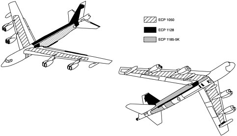
FIGURE A-2 General locations for B-52G/H structural improvements.
aluminum in the primary structure of the airframe. These alloys have relatively poor fracture properties and are susceptible to corrosion and SCC. The group recommended that a detailed DADTA be conducted. This was performed during 1979 and early 1980 and the tracking program was upgraded. The DADTA identified about two dozen critical areas requiring inspections and potential future modification. It also concluded that, with inspections, modifications, and continued tracking of the aircraft, the aircraft could be operated safely into the twenty-first century.
In 1990 a B-52 structures working group was formed with representatives from the Oklahoma City ALC and engineers from Boeing with expertise in fatigue, stress, design, and materials. The purpose of this group was to develop solutions to current structural problems and to address long-term aging issues. Some specific problems they have addressed in the past several years are
-
cracking in the bulkhead at body station 694
-
fatigue cracking in flap tracks
-
cracking in the side skin of the pressure cabin
-
cracking in aft body skins
-
cracking in the upper surface of the wing
-
fatigue cracking in the thrust brace lug of the forward engine support bulkhead
Force-wide inspections and identified corrective actions for each of these problems have either been or are being implemented. In addition, a tear-down inspection of a retired service aircraft was conducted to assess the corrosion problems on the aircraft, and an updated DADTA was completed in 1995. The corrosion tear-down inspection revealed only relatively minor problems, and it was concluded that, with continued use of corrosion-preventative compounds, corrosion should not be an issue. As part of the DADTA, an estimate was made of the lower-bound economic life of the airframe. It was determined that the limiting component was the upper surface of the wing, where it was determined that the lower-bound economic limit was about 32,000 hours of the current use spectrum. Based on the current utilization rate, it was estimated that this would allow the aircraft to be used beyond the year 2030. This is illustrated in Figure A-3.
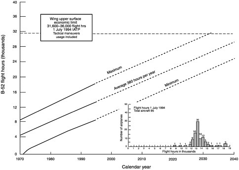
FIGURE A-3 B-52H current use rate.
B-1B
The North American Rockwell B-1 strategic bomber program was awarded in June 1970. The program was to consist of 4 prototypes and 244 production aircraft. The first prototype flew in December 1974, and the program was terminated in 1977 in favor of cruise missiles. A 100-aircraft program was resurrected in October 1981 as the B-1B. The contract was awarded in January 1982 and the first flight of the B-1B was in October 1984 and the initial operational capability (IOC) was in October 1986. Currently, there are 81 B-1Bs in the Air Force and 14 in the Air National Guard.
Although the initial contract did not have damage tolerance design requirements, design changes were made in 1971 to implement them. This represented the first Air Force aircraft designed to such requirements. Although the requirements had not yet matured to the level reflected in MIL-STD-1530A and MIL-A-83444, which were released in 1975, the requirements did include a safe crack growth design that significantly influenced the materials selection. The material selected for the wings was 2219 aluminum, which had been used successfully in the Apollo space program. Titanium 6A1-4V was used for the wing carry-through structure and the internal structure of the horizontal tail, and a tough low-carbon steel alloy was used for much of the empennage support structure. Considerable effort went into obtaining fracture toughness data and fatigue crack growth data for all of the alloys used in the B-1. It was these data that formed the start of the Air Force Damage Tolerance Handbook.
Designed to be damage tolerant, the in-service structural inspection requirements would be expected to be minimal if the aircraft were flown close to their original design loads spectrum. However, as with many other combat aircraft, the B-1B actual use spectrum is more severe than the original design spectrum. The load factor occurrence have been in excess of the design use, particularly in traffic patterns. In fact, there have been occurrences of load factors in excess of the design limits for the aircraft. Also, the fuel reserves at landing are in excess of those assumed during the design. The reason for this is the desire to be able to avoid commercial airports in the event of the need to use an alternate airport. The consequence of the increased load factor occurrences and increased landing weights is increased fatigue damage rate (i.e., the rate of flaw growth) and thus shortened inspection intervals. This could become a problem in the wing structure if fastener removal becomes necessary for inspection because the B-1B uses interference fit fasteners in the wing. This is currently being investigated by the Oklahoma City ALC to determine the alternatives. Obviously, the best solution would be to return to the original use for which the aircraft was designed, if possible, since the aircraft are still quite young and the damage to date may not be excessive.
To date, the fatigue cracking and corrosion problems on the B-1B airframes appear to be minimal and, unlike many earlier aircraft, more emphasis was placed on selecting materials with increased corrosion resistance. One exception has been the horizontal tails that have encountered high-cycle fatigue damage to the internal titanium sine wave spar structure. The tail is located just above the exhaust wake of the engines, but well within the high-acoustic-noise envelope. This placement of the tail was intentional to achieve high-performance turns at low velocities using the engine exhaust to increase the control power exercised by the horizontal tail. Although the original ground fatigue tests and ground vibration tests showed no problems and the natural frequencies of the tail were beyond those at which acoustically driven problems would be expected, flight experience showed that high-cycle fatigue cracking occurred very early in the service life. After considerable effort on the part of the contractor, the problem was found to be caused by the fact that the production tails had gaps between the skins and the titanium substructure. This caused bending of the spar and rib flanges during assembly, producing high sustained stresses in the flanges. In addition, there was loosening of the blind fasteners in flight. These factors caused the response frequency of the overall tail to be reduced such that it fell within excitation frequencies of the engine acoustic noise. The contractor developed an overall analysis of the dynamic response of the tail, which in turn has led to a modification that is believed to have solved this problem.
F-15
The McDonnell Douglas F-15 was the winner of an Air Force competition for a new air superiority fighter aircraft in December 1968. The first flight of the aircraft was in July 1972 and IOC was in January 1976. Since the start of the program, five different models have been built for the Air Force (plus models for foreign military sales). These are the single-seat A and C models, the two-seat B and D models, and the dual-role two-seat F-15E Strike Eagle. The Air National Guard currently has 116 of the A and B models, and the Air Force has 621 of the other models. The structural configuration of the aging A through D models are much the same.
The F-15A/D models were designed under Air Force ASIP requirements in the late 1960s prior to the adoption of damage tolerance requirements; however, full-scale fatigue and static testing were also conducted. A complete DADTA was performed in the early 1980s to update the maintenance program based on the damage tolerance approach. In the initial design of the F-15, McDonnell Douglas incorporated a fatigue-resistant interference fastener system, but ignored its beneficial effects when establishing the operating stress levels for the structure. This turned out to be fortuitous in that it allowed some margin for increase in severity of the loads spectrum. In fact, the growth in weight of the aircraft and changes in load factor severity have significantly increased the spectrum
severity, causing the time required to grow an initial flaw to critical size to be reduced to about one-fourth of its original value. This increased severity was noted through the IATP conducted by the Warner-Robins ALC, and because the change was so significant, it was decided to conduct an additional full-scale fatigue test to the increased severity spectrum. This test was conducted at the Wright Laboratories test facility at Wright-Patterson AFB. The results of this test indicate that the original operational service life goal of 8,000 hours should still be attainable. However, the increased use severity will increase the inspection burden, and some of the wing inspections could become particularly onerous because of the current lack of NDE capability to inspect for small cracks without removal of the fasteners. McDonnell Douglas is currently using the results of the tear-down inspection of the fatigue test aircraft and crack growth analyses to obtain a better estimate of the actual service life expectancy of the F-15.
When the F-15E was designed, the MIL-STD-1520 and MIL-A-83444 damage tolerance requirements had been implemented. This meant that some areas of the original F-15 structures design had to be changed to meet these requirements, and some additional testing was required to prove the structural integrity. To date, the E models seems to be flying close to their design use spectrum.
The structural problems that have been encountered in service on the F-15 fall into the five following general categories:
-
damage to honeycomb structure
-
buffet-induced cracking
-
acoustic-induced cracking
-
corrosion in nonhoneycomb structure
-
low-cycle fatigue cracking
The F-15C and E models have experienced honeycomb water intrusion, corrosion, disbonds, cracks, and in-flight loss of various secondary structures such as wing tips, ailerons, flaps, fin leading edges, and horizontal tail components. These problems have been caused by leak paths, inadequate bond durability, and unexpected dynamic loading. The current solution has been to perform a patch repair or to replace the components with improved honeycomb components.
The areas of the F-15 structure that have encountered buffet-induced cracking are illustrated in Figure A-4. Twintailed aircraft, such as the F-15 and the Navy's F-18, use vortices generated from the fuselage at high angles of attack to provide additional rudder power for control. Unfortunately, these same vortices provide a very turbulent flow field at intermediate angles of attack and subject the tails to a high-frequency, asymmetric loading that causes early high-cycle fatigue cracking and partial failure of the tail structure. The first sign of cracking due to these loads in the F-15 was in the pod attachments at the top of the tails. Local repairs did nothing but move the failure points and reduce the life. It took a careful analysis of the entire tail response and fuselage attachment stiffness by McDonnell Douglas to simulate the tail vibration modes and deflections that led to these failures and provide the insight to arrive at a solution. This involved increasing the overall stiffness of the tail by adding graphite composite plies to attenuate the vibration. In the case of wing cracking due to buffet, as indicated in Figure A-4, the cause was flow detachment over the outer wing at even modest angles of attack that resulted in high-frequency out-of-plane loading. These loads vibrated the skins and integral stiffeners and caused cracking of the rib mouseholes through which the spanwise stiffeners ran. Again, local repairs did not solve the problem. Eventually, damping systems were applied to the stiffener/rib connections to reduce the problem, and an alternate method of connecting the stiffener cap to the rib was developed.
The primary acoustically induced high-cycle fatigue cracking on the F-15 was encountered on the E model after stores (externally mounted weapons and systems) were qualified for use on the aircraft. The E model is configured for both air-to-air and air-to-ground attack missions, and in the air-to-ground mission radar evasion often requires low-altitude, high-speed cruise and dash to the target. With multiple stores attached to pylons beneath the wings, shocks are formed, which cause high acoustic vibrations to occur on certain skin panels of the fuselage. These vibratory loads have been high enough to cause high-cycle fatigue cracking of some skin panels. To permanently fix such damage, it is necessary to design the repaired structure such that its natural frequency is out of the range of the shock impingement frequency. This is a complex problem that requires knowledge of both the excitation sources and the structural responses. The current approach to fixing these problems on the F-15 has been to replace the damaged structure with parts with greater thickness to increase strength and to apply damping material. Additional research in understanding and developing repairs or modifications for these types of problems (e.g., composite repairs and better damping materials) appears worthwhile.
The corrosion problems in nonhoneycomb structure on the F-15 have been minimal. There have been some problems in the fuselage fuel tank, the outboard leading-edge structure of the wings, and the flap hinge beam. The current solution has been to improve drainage, repair, and replace.
The primary low-cycle fatigue cracking that has occurred in service to date has been in the upper surface of the wing in compression-designed structure that was not sized for fatigue during the initial design. Also, there has been one fuselage cracking problem. The specific low-cycle fatigue cracking locations were as follows:
-
upper wing surface stringer runouts
-
upper wing spar cap seal grooves
-
front wing spar conduit hole
-
upper in-board longeron splice plate holes
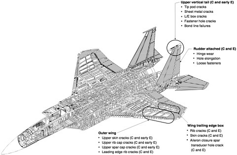
FIGURE A-4 F-15 buffet-induced problems.
None of these problems is life limiting, and in all cases preventive repairs have been designed and installed on the aircraft.
F-16
The first General Dynamics YF-16 prototype flew in January 1974. After winning the fly-off against the YF-17 prototype, eight more development aircraft (i.e., six single-seat A models and two two-seat B models) were built. The production authorization was announced in the spring of 1978. The first flight of a production F-16A was in August 1978 and IOC was in 1979 at the 388th Tactical Fighter Wing at Hill AFB. The Air Force currently has 809 F-16s in the active forces, 73 in the Air Force Reserve, and 631 in the Air National Guard.
When the full-scale development began in January 1975, the airframe was designed to the ASIP requirements in MIL-STD-1530A and the damage tolerance requirements in MIL-A-83444. Materials and stress levels were selected to preclude the need for structural inspections throughout the design operational life of 8,000 hours of the design use spectrum. The structural arrangement of the F-16 is shown in Figure A-5. The aircraft was designed for a limit load factor of 9 g's to what was thought to be a severe load factor exceedance curve. The design gross weight of the aircraft was 22,500 lb., and the design mission distribution was
-
55.5 percent air-to-air
-
20.0 percent air-to-ground
-
24.5 percent general
A full-scale static test was conducted under more than 100 different test loading conditions. All test objectives were met, and no structural modifications were needed. A full-scale fatigue (durability) test was conducted to two lifetimes of the design use spectrum and was completed in March 1978. Some cracking occurred in the fuselage center section bulkhead shear webs, and action was taken to reinforce these areas in the production aircraft. Also, a few other cracks occurred at local stress concentrations, which required some local changes in the production aircraft.
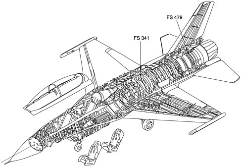
FIGURE A-5 F-16 structural arrangement.
Almost immediately after its introduction into operational use, the gross weight of the aircraft started to increase due to increased payloads, and the aircraft use changed. In 1981, General Dynamics made an assessment of the structural capability of the F-16 at a gross weight of 23,500 lbs. and concluded that the aircraft was adequate from the standpoint of static strength. The effect of the increased weight and mission changes on the fatigue was still uncertain because there was still only a limited amount of tail number tracking data available. By the mid-1980s the new mission distribution was
-
28 percent air-to-air
-
57 percent air-to-ground
-
15 percent general
Also, the data from the IATP began to indicate that the load factor (Nz) exceedances were more severe than had been assumed in the initial design for all three missions. It was believed that these increased exceedances were caused by an "Alpha-g" limiter that allowed the pilots to accomplish significantly more high-"g" maneuvers without fear of overloading the aircraft. This, combined with the continuing increases in aircraft weight (e.g., the design gross weight for the F-16C/D, block 50, grew to 28,750 lbs.), resulted in significantly increased stress exceedances and reduced fatigue life. In February 1984 the F-16 Systems Program Office asked the Aeronautical Systems Division's engineering and technical management organization (ASD/EN; now ASC/EN) to perform an independent assessment of the F-16 structural integrity program. Based on this review it was decided that the use severity dictated the need for a new full-scale static and durability test.
During the full-scale static test in October 1987, the left wing failed at approximately 85 percent of the design ultimate strength (as a result of the maximum wing bending moment being 25 percent higher for the F-16C/D than for the original F-16A/B). A modification was developed and the static test was successfully completed. The full-scale fatigue (durability) test was begun in September 1987. A primary purpose of this new test was to identify the areas of the structure that had become fatigue critical as a result of the more severe and different use of the aircraft. The test revealed about a dozen new critical areas by October 1989, when it had reached 7,330 cyclic test hours. At this point the test was stopped for replacement of the wing attach bulkheads (i.e., fatigue cracks
were first noted in the bulkheads at about 4,000 cyclic test hours). Damage tolerance analyses were performed to establish the safety limits and inspection requirements for all of critical areas.
In early 1991, the Air Force, led by ASD/EN, conducted another independent review of the F-16 structural integrity program. By this time there were 18 critical areas or locations identified in the airframe. Of the 18 areas, 15 had been identified by either the 1987/1989 full-scale fatigue test or subsequent component testing. Of these 15,6 had also shown up as cracking problems on service aircraft. In addition, two more areas had shown up on service aircraft that had not been identified by fatigue testing. One was at a tab radius of the wing attach bulkhead and the other was at a pad radius of the vertical tail attachment bulkhead at fuselage station 479. It was later discovered from the flight recorded data that the actual service loading spectrum for the vertical tail was more severe than that which had been applied during the 1987/1989 full-scale fatigue test because of rolling maneuvers with rudder input from the pilot. One critical area was identified by analysis only. The review team concluded that the potential for future service problems was high, and they made a number of recommendations with regard to future inspections and modifications.
By mid-1995 more service cracking had been discovered, generally at times fairly close to what had occurred during fatigue testing, and repair and modification plans were either in place or being defined for the various models (i.e., A, B, C, and D) and blocks of aircraft within a model. The six general areas requiring repair or modification are shown in Figure A-6, along with the ECP number that addressed the F-16C/D block 40 modifications.
In November 1996 the committee received a briefing by the system program director's representative on current structural problems on the F-16. The six problem areas that were highlighted were
-
cracking of the vertical tail attachment bulkhead at fuselage station 479
-
cracking of fuel vent holes of the lower wing skin
-
cracking of the wing attach bulkhead at fuselage station 341
-
cracking of the upper wing skin
-
fastener problems on the horizontal tail support box-beam
-
cracking of the ventral fin
In each case, the current repair and replacement concepts were described. Concerns about future fatigue cracking were expressed, along with the possibility of hidden corrosion. However, corrosion was not discussed as being a current problem.
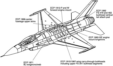
FIGURE A-6 F-16 structural modification areas.
A-10
The Fairchild-Republic A-10 was selected by the Air Force over Northrop's competitive A-9 prototype in January 1973. This was followed by full-scale development, and production began in 1975. The IOC was in 1977 and the first units were deployed to Europe in 1978. The Air Force currently has 223 A/OA-10s in the active force, 51 in the Air Force Reserve, and 101 in the Air National Guard. As of April 1996 the flight hours on the aircraft ranged from about 3,500 to about 6,800, with an average of about 5,000.
The structural configuration of the A-10 is shown in Figure A-7. The original design life for the A-10 was 6,000 hours to a design use spectrum that was developed largely from data that had been required from previous ground attack aircraft such as the A-7 and F-4. Also, the Air Force ASD was convinced by the operators and the contractor that only mission-required fuel should be used in the development of loading spectra for the aircraft. Both of these factors turned out to be serious errors. First, the design spectrum failed to recognize that this aircraft, when operating at low levels, would be subjected to many more evasive maneuvers than had been experienced previously be either the A-7 or the F-4. This resulted in a higher number of load exceedances than the aircraft was designed for. Second, the Tactical Air Command operated the aircraft with full fuel tanks rather than using only mission fuel as was originally intended. The combination of these two factors resulted in the A-10 actual use being about three times more severe than the original design use. Further compounding the problem was the recognition, early on, that the 6,000-hour design life was too low and that it should be increased to 8,000 hours. Although the goal of the original full-scale fatigue test was to achieve two lifetimes (i.e., 12,000 hours) of the original design spectrum (which it did obtain with some problems), it was necessary to extend the testing and increase the severity of the test spectrum. Thus, after testing to 12,000 hours of the original spectrum, the test was continued another 3,480 hours of the new severe spectrum (called spectrum 3) with repairs to the wing structure. In addition, it became apparent that there was a need to perform a full DADTA using the new spectrum to determine the safety limits and inspection
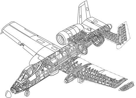
FIGURE A-7 A-10 structural arrangement.
requirements for all critical areas for both modified and unmodified structure. Accordingly, an on-site Air Force senior structures engineer was assigned at Fairchild-Republic from June 1978 to September 1979 to lead this effort. A total of 68 critical areas were identified and the inspection and modification needs defined. Additional full-scale wing, empennage, and forward fuselage component fatigue testing to the spectrum-3 loading was also accomplished.
The full-scale fatigue testing resulted in a number of cracking problems. In the center panel of the wing there was skin, spar cap, and spar web cracking at numerous fastener holes. As a result, up to 1,500 holes per wing were cold worked as a near-term maintenance measure. In addition, the structure was redesigned to incorporate thicker lower skins and spar caps to achieve the desired 8,000 hours of spectrum-3 use. There were also cracks in web of the front spars emanating from nutplate holes around access cutouts. In the outer wing panels, fatigue cracks from fastener holes resulted in complete wing fracture at wing station 135 and 178. As a result, the lower skin was redesigned with a thicker three-step skin. This change was incorporated in production and retrofit on operational aircraft. In addition, there was cracking of the webs of both the front and the mid spars. In the fuselage, cracking occurred at the upper auxiliary longeron splice strap at fuselage station 524, and the frame at fuselage station 405 failed during the test at approximately 82 percent of the design lifetime. Both areas required redesign and changes to the operational aircraft. A fatigue cracking problem requiring redesign was also encountered when testing the main landing gear.
In addition to the cracking that occurred during the fatigue testing, there have been a number of other fatigue cracking problems discovered in operational aircraft as a result of the in-service inspections that have been performed. These have occurred at the locations listed below:
Wing:
-
auxiliary spar cutout of the center section rib at wing station 90
-
outer panel front spar web at wing station 118 to 126
-
outer panel upper skin at leading edge
Fuselage:
-
center fuselage forward fuel cell floor at the boost pump
-
forward fuselage gun bay compartment
-
forward fuselage lower longeron and skin at fuselage station 254
-
center fuselage overwing lower floor panel stiffeners
Nacelle:
-
aft nacelle hanger frame
-
aft nacelle thrust fitting
-
engine inlet ring assembly skin/frame
Main landing gear:
-
shock strut outer cylinder
In 1991 a follow-on or update to the 1978/1980 DADTA was performed. The number of critical areas or locations had grown to 103. This assessment utilized an updated spectrum based on 477,440 total hours of individual aircraft tracking and 5,895 hours of flight data recorder data. These data indicated that the actual use was still more severe than the original design use, but not as severe as spectrum 3 which was based on much less flight data. The safety limits and inspection requirements were adjusted accordingly.
During the November 1996 review with this committee, the representative of the A-10 system program director listed the current known fatigue cracking problems on the service aircraft. In addition to some of the service problems listed above, he noted that fatigue cracking was occurring in the forward fuselage upper crown skin and at the lower wing skin fastener holes and pylon stud holes at wing station 23. Also, areas of the airframe where corrosion has been found were described, including
-
Exfoliation corrosion:
-
2024-T351 aluminum lower wing skin (chemically milled step)
-
7075-T6 aluminum upper wing at the leading edge
-
2024-T3511 aluminum lower front spar cap
-
other local areas in lower wing skin
-
7075-T6 aluminum fuselage bottom skin 2024-T3/7075-T6 aluminum fuselage side skin and beaded pan
-
2024-T3511 aluminum horizontal stabilizer upper spar caps
-
-
Pitting corrosion:
-
9Ni-4Co-0.3C steel wing attach fitting bushing and lug bore
-
main landing gear fitting attach bolts
-
7075-T6 aluminum aft fuel cell aft bulkhead
-
2024-T351 center fuselage upper longeron
-
-
SCC:
-
wing attach bushing flange
-
main landing gear attach bolts
-
OTHER AIRCRAFT OF THE AIR COMBAT COMMAND
E-3A (AWACS)
Boeing was awarded a contract for two prototype airborne warning and control system (AWACS) aircraft in July 1970. The first production aircraft designated the E-3A was delivered to the 552nd Airborne Warning and Control Wing at Tinker AFB, Oklahoma, in March 1977. The Air Force currently has 32 E-3s in the active inventory. As of September 1995, the flight hours on these aircraft ranged from 9,809 to 15,872, with an average of 13,994. The number of flights ranged from 1,358 to 2,391, with an average of 1,885.
The E-3 is a derivative of the Boeing commercial 707-320B aircraft. The primary structural modifications were made to the aft fuselage to attach the support struts for the large fiberglass rotodome assembly. Designed in the early 1950s, the 707 airframe contains many parts made from the corrosion-susceptible 7000-series aluminum alloys in the T6 condition; however, the lower wing skins and the fuselage skins are made from the tougher 2024-T3 aluminum. The basic structure was designed to be fail-safe and was certified to the required fail-safe residual strength requirement then in existence (i.e., to be able to carry 80 percent of limit load after failure of a structural member or a large partial failure). At that time there was no requirement for fatigue testing and none was performed on the wing. Hydro-fatigue testing and fail-safe testing was performed on the fuselage. The fail-safe testing consisted of dropping guillotine blades through large sections of the fuselage, and more than 30 such tests were conducted during the aircraft development.
In 1976 the Air Force contracted with Boeing to perform a DADTA on the E-3 to establish structural inspections based on the MIL-A-83444 damage tolerance requirements and to assess the probable durability of the airframe in the anticipated Air Force use. Comparative analyses between the commercial 707 and the E-3 were performed to allow the interpretation of the commercial 707 (lead-the-fleet) service experience in relation to future E-3 maintenance needs.
The original design life goal for the commercial 707 aircraft was 20,000 flights and 60,000 flight hours and, as can be seen in Table 3-3, there are 707s that have exceeded these goals that are still in commercial service. As noted above, the average E-3 has accumulated less than 10 percent of the 20,000-flight commercial design goal, and as such, the onset of WFD should not be a concern for a number of years.
During the review with this committee in November 1996, the representative from the E-3 program at the Oklahoma City ALC indicated that the structural service experience included some isolated fatigue damage and generalized corrosion of the 7000-series aluminum alloys and especially the 7178-T6. The specific problems noted were:
-
Fatigue and corrosion:
-
rudder skins
-
spoiler actuator clevis
-
-
Exfoliation corrosion:
-
7XXX-T6 upper wing skin
-
leading-edge slats
-
main landing gear door
-
fillet flap
-
magnesium parts
-
fuselage stringer 23
-
-
Delaminations and disbonds:
-
windows, floor panels, and nose radome core
-
-
Wear:
-
antenna pedestal turntable bearings
-
E-8 (JSTARS)
The Northrop Grumman E-8 joint surveillance and attack radar system (JSTARS) program consists of two E-8A prototypes, one preproduction E-8B, and nineteen production E-8Cs. All of the E-8s are scheduled to be delivered to the 93rd Air Control Wing at Warner-Robins AFB, Georgia, by 2004, with the first production deliveries in 1997. The E-8 airframes are used Boeing 707 commercial aircraft. The flight hours on the first ten aircraft selected for production JSTARS range from about 40,000 to 64,000 hours, with an average of 53,615 hours. The number of flights on these aircraft range from about 17,200 to 22,250, with an average of 19,861. The planned future use for the aircraft is 16 years and 20,000 flight hours; however, this could very well be extended if the concept remains successful. The original design life goal for the commercial 707 aircraft was 20,000 flights and 60,000 flight hours.
During the refurbishment and modification of the initial commercial 707s to the E-8 configuration, corrosion was found to be quite extensive in the aircraft fuselage. Many longitudinal lap splices were opened up (i.e., the fasteners were removed) and the corroded materials were ground away. Where the corrosion was too severe, the skin panels and stringers were replaced. Fourteen complete panels and four partial panels removed from the first two production E-8s were sent to Boeing for detailed inspection. Both of the aircraft from which these panels were removed had seen about one design lifetime (i.e., approximately 20,000
flights and 60,000 hours) of commercial service and both had corrosion damage ranging from light (i.e., less than 0.001 in. deep) to severe (i.e., more than 0.01 in. deep). The purpose of the inspection was to determine if there was any indication of fatigue crack initiation, which could portend the future onset of WFD, and if corrosion was contributing to the crack initiation. Thousands of fastener holes, spot welds, and repair details were examined by a close visual inspection, followed by detailed inspections (under 20X magnification) of about 500 fastener holes that were in the more-severely corroded areas. Selected fastener holes were examined further using stereoscopic microscopes. No fatigue cracks were found in any of the fastener holes or other structural details. This finding, combined with the results of the original hydro-fatigue testing and the results of fatigue testing performed on the KC-135 (which is of similar construction in many areas), provided the Air Force with confidence that the E-8 fuselages (as well as the C-18 and the VC-137 fuselages that were also derived from the 707) will not experience the onset of WFD in the near future.
Extensive corrosion was also found around fasteners in the upper wing skins. The corrosion in these areas was ground out, many fastener holes were then cold worked, and many repairs were made in compliance with the Boeing repair manual for the 707 aircraft.
Because of previous evidence of some fatigue cracking in commercial 707 wings (i.e., primarily in the 7075-T6 aluminum stringers), the Air Force contracted with Boeing to perform detailed tear-down inspections of some sections of wings taken from two 707 aircraft that had been in storage at Davis Monthan AFB in Tucson, Arizona. The purpose of these inspections was to obtain data to predict when the 707 wings might be expected to experience the onset of WFD. One aircraft was a-300-series aircraft, such as the E-8s, that had 57,382 flight hours and 22,533 flights (approximately one design lifetime of commercial use). The other aircraft was a-100-series aircraft that had 78,416 flight hours and 36,359 flights. Figure A-8 shows the plan form of the 707-300 wing and the five sections that were removed for detailed inspection. These inspections revealed 1,084 small fatigue cracks in fastener holes in the 7075-T6 aluminum stringers and 591 small fatigue cracks in the fastener holes in the 2024-T3 aluminum skins of the 707-300 aircraft. The findings from the inspection of the 707-100 wing yielded somewhat fewer cracks (i.e., a total of 673 stringer and skin cracks were found) because a much smaller area of the wing was inspected. Ninety-six percent of the fatigue cracks that were found in the 707-300 were in the size range from 0.01 in. to 0.06 in., and 4 percent were greater than 0.06 in. long. The largest stringer crack completely severed one flange of the stringer, and the largest skin crack was <0.20 in. out of each side of the fastener hole.
The questions that needed to be answered with regard to these tear-down inspection findings were:
-
Are the findings representative of the cracking that could be expected to exist in the other used commercial 707-300 aircraft that have had a similar number of flights or flight hours?
-
Are the cracks that were found of sufficient size and density to constitute the onset of WFD (i.e., are they of sufficient size and density to degrade the fail-safe residual strength of the wing to below the required level)?
-
If they have not yet reached the size and density necessary for the onset of WFD, when is it predicted that this will occur?
With regard to the first question, nothing was identified to indicate that the 707-300 aircraft that was torn down was not typical of any other 707 aircraft with similar use. Thus, it must
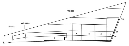
FIGURE A-8 Boeing 707 wing tear-down locations.
be assumed that similar fatigue cracking exists in the wings of all 707s, which have accumulated as many flights and flight hours.
The answer to the second and third questions depends on the fail-safe damage size and residual strength level that is required. The ASC/EN obtained the assistance of Boeing to analytically determine the residual strength of the wing, assuming the failure of two adjacent skin panels and the central stringer due to discrete source impact (e.g., impact from an engine burst or gunfire) or due to any other cause. The results of this analysis indicated that, with this damage size, the remaining wing structure was barely able to sustain the limit load under the assumption that there was no fatigue cracking in the adjacent stringers or skin panels. Although this damage size and residual strength exceed the original certification requirement for the 707 aircraft,3 it is the typical design criteria for present day commercial aircraft. Also, ASC/EN considered it to be an appropriate fail-safe requirement for the E-8, recognizing that the E-8 could be operating in a much more hostile environment than the typical commercial 707 aircraft. Using the results of the residual strength analyses and the inspection findings from the tear down of the 707-300 aircraft, the ASC/EN, with the assistance of Boeing, developed crack distribution, crack growth, stress distribution, and critical stress functions necessary to perform a risk assessment of the E-8 wings. The results of this assessment indicated that, for the tear-down 707-300 aircraft, the risk of an aircraft loss—given the discrete source damage—was unacceptable beyond about 50,000 flight hours (i.e., the onset of WFD was at about 50,000 hours).
It is the committee's understanding that the Air Force is currently in the process of reviewing the options available to deal with this wing cracking problem in the E-8. For the lower-time aircraft, where the cracks are still very small, the option may be to remove the fasteners, clean the cracks out by oversizing the holes, and then cold expanding the holes to delay reinitiation. Where it is not possible to clean the cracks out by oversizing, the use of composite patches may be an option. For the higher-time aircraft the only option may be to replace the skin panels and stringers. It is also the committee's understanding that Boeing is assessing the implications of the tear-down inspection findings on the degradation of the fail-safety of the remaining commercial 707 aircraft and determining the need for corrective actions.
The findings also have obvious implications to the degradation in the fail-safety of the other 707 commercial-derivative aircraft that have accumulated a high number of flights and flight hours (i.e., some C-18 and VC-137 aircraft).
C-130
The Air Force selected the Lockheed proposal for what was then designated as a heavy cargo aircraft in 1951. After winning the competition, two YC-130 preproduction or prototype aircraft were designed and built during the period 1952 to 1954 with the first flight in August 1954. The first production contract was awarded in 1953 for seven C-130A models with the first flight in April 1955. The IOC was in 1956. The C-130s have five basic models: the A, B, E, H, and J. The current production model is the H with the future J model incorporating new engines and a two-man heads-up display cockpit. The Air Force currently has 311 C-130s in the active force, 141 in the Air Force Reserve, and 242 in the Air National Guard, for a total of 694 aircraft. Except for ten AC-130As still in the Special Operations Command, the C-130 force consists of E and H model aircraft. All of the B model aircraft were phased out of the Air Force's inventory by 1995. Nearly one-fourth of all the Air Force's C-130s are used in the various special purpose missions listed below.
-
gunship (AC-130A/E/H/U)
-
aerial drone launcher (DC-130E/H)
-
electronic combat (EC-130E/H)
-
search and rescue (HC-130H)
-
helicopter tanker (HC-130N/P)
-
ski airlifter (LC-130H)
-
missile tracker and satellite recovery (JC-130H)
-
multirole and special operations (MC-130E/H)
-
weather reconnaissance (WC-130E/H)
The E model aircraft were delivered to the Air Force between 1961 and 1972, and the H models have been supplied since 1973. The average age of all the C-130s in the Air Force inventory is about 25 years.
Like most military aircraft designed in the 1950s and 1960s the C-130s used mostly 7000-series aluminum alloys heat treated to the T6 condition, and as a result they have encountered many corrosion and SCC problems over the years, in addition to many fatigue cracking problems. Some of the fatigue cracking problems are attributable to the large amount of low-level flying associated with the many special uses of the aircraft. The first serious problems occurred with corrosion and cracking of the center wing structure. This led to a redesigned center wing being incorporated in the production of the E model in 1968 and, in the period from 1968 to 1972 the center wings were replaced on all B models and the earlier E models.
Although there have been some minor improvements, the same center wing has been in production since the redesign in 1968. During the 1970s it was discovered that the damage tolerance of the outer wings was severely degraded due to fatigue cracking plus some faulty depot maintenance actions by some commercial contractors. In the 1979 to 1981 time
period there was a miniDADTA conducted, which focused on this outer wing problem. During 1981 to 1983, a more complete DADTA was conducted. The results of these assessments led to the recommendation that the outer wing panels of all aircraft prior to Lockheed serial number 4542 be replaced with a new lower-stressed H model outer wing that was designed and put into production in 1984. During the period from 1984 to 1988, all of the outer wings on the Air Force C-130s built prior to Lockheed serial number 4542 were replaced. By 1993 fatigue cracking problems were again appearing in the center wings on certain versions of the C-130s assigned to the Special Operations Command (i.e., HC-130N/P, AC-130H, and MC-130E). This led to the initiation of a program to again replace the center wings on these aircraft with new center wings, which contain design improvements to accommodate the more severe use of this command.
During the 1992 summer study of the SAB, which addressed the technologies to support the Air Force's Global Reach/Global Power Concept, the board's Mobility Panel reviewed the structural status of the airlift aircraft. With regard to the C-130 they noted that the wings should not be a structural problem in the near future because of the many replacements that have been accomplished. On the other hand, they also noted that the average remaining life of the fuselage was quite low based on predictions made by Lockheed. Lockheed predicted an average remaining life for the E model fuselages of about 10,000 hours, with that of the high-time aircraft being considerably less. The aircraft were typically accumulating about 700 to 800 hours per year. In addition, the SAB pointed out that the validity of the estimate was questionable because of the lack of good fatigue test data (i.e., the full-scale fatigue test performed on the A model in 1956 consisted of only pressure testing to 20,000 cycles, and there had been structural changes since then). They recommended that the Air Force Matériel Command (AFMC) make a detailed review of the C-130 fuselage life estimate to assess if a new full-scale fatigue test was justified and what other life-extension measures were needed.
Although this committee saw no evidence to indicate that the Air Force acted on the SAB's 1992 recommendation, in March 1996 the Director of Logistics of the Air Combat Command wrote a memorandum to AFMC Headquarters requesting their assistance in updating the service life limit for the C-130 fuselages, since they were reaching the life limit projected by Lockheed. In response to this request, AFMC put together an ad hoc team, consisting of representatives from ASC/EN, Warner-Robins ALC, Wright Laboratories, and the FAA to investigate the issue. This ad hoc team identified five options for obtaining an improved estimate of the service life limit of the C-130 fuselage:
-
A full-scale durability test (i.e., a full-scale fatigue test), which simulated both internal pressure and external flight loads.
-
A detailed tear-down inspection of a high-time C-130 operational aircraft to identify the possible onset of WFD, critical areas, and corrosion problems.
-
A large panel fatigue test of the rear fuselage upper crown skin area.
-
A detailed DADTA of the fuselage.
-
A combination of options 2, 3, and 4.
The team recommended option 5 as the most cost effective. In addition, they recommended the continued enforcement of the C-130 corrosion tracking program and the use of current detection methods to search for corrosion and to develop corrosion signatures of the C-130s at each programmed depot maintenance to help determine trends in corrosion damage.
EF-111A
The EF-111A are F-111A aircraft produced by General Dynamics that have been converted to electronic countermeasures tactical jamming aircraft by Grumman. The original F-111 contract was awarded in 1962, and the first two prototype aircraft flew in 1964. The first production F-111A entered service in 1967. The F-111As that were later converted to EF-111As were built in the late 1960s. In 1975 Grumman received a contract to convert two F-111As to EF-111A prototypes. The first flight of an EF-111A with complete electronic systems was in 1977. After four years of operational testing, the first operational aircraft entered service in 1981. A total of 42 EF-111As were produced, with the last one delivered to the Air Force in 1985. There are currently 37 in the Air Force inventory. The average age of their airframes is about 29 years and the average flight hours is about 6,000. The current Air Force plan is to retire all of these aircraft over the next four or five years and have the Navy assume the mission using the Navy's EA-6B aircraft.
The F-111 airframe has a significant amount of high-strength D6ac steel in the wing carry-through structure, the tail support structure, and the fuselage longerons (see Figure A-9). Most of these components are heat treated to 220,000-psi tensile strength with some heat treated to the 260,000- to 280,000-psi range. The remainder of the airframe structure is fabricated mostly from aluminum alloys. The design load factors (Nz values) are -3 g to +7.33 g, and the original design life goals were 4,000 flight hours and ten years of service. At the time of the original design, the Air Force had not yet developed and implemented damage tolerance design requirements. The structure was designed with the so-called safe-life approach using a Miner's rule fatigue analysis. The operational life was limited to that demonstrated by the full-scale fatigue test reduced by a factor of four to account for data scatter.
A full-scale static test program was conducted, and after several local redesigns to correct strength deficiencies, the test
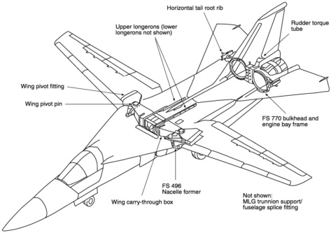
FIGURE A-9 F-111 D6ac steel components.
was completed successfully. A full-scale fatigue test program was initiated in 1968, with the entire program lasting about six years. The program started using a complete airframe test article with the objective of completing four lifetimes of testing or 16,000 test hours of a relatively severe block-type spectrum. However, after only 400 cyclic test hours, the wing carry-through box failed due to a manufacturing quality problem. As a result of the severe damage to the test article, the test program was revised to continue testing on separate major components (i.e., wing, fuselage, etc.) rather than the complete airframe. Also, the test spectrum was revised and the test goal increased to 24,000 test hours. Subsequent failures of the wing carry-through boxes occurred at 2,800 and 7,800 test hours. As a result of these failures, taper-lock fasteners were installed in the lower part of the box and some other design changes were made. At 12,400 test hours, a failure occurred at the wing pivot fitting. This failure resulted in the development of a boron-reinforced composite doubler modification that was the first use of advanced composites to reduce the stress levels in metallic aircraft structures (boron reinforcements were also used later on fuselage longerons on the B-1 bomber). The wing then completed the 24,000 test hours without any further significant events. The test was then continued beyond the contractual requirements to 40,000 test hours. At this point it was subjected to constant amplitude cycling to the bending stress associated with a 5.8-g maneuver load. Failure occurred in the aluminum skin splice to the pivot fitting at 10,151 cycles. The horizontal stabilizers were also subjected to 40,000 test hours and were found to be free of fatigue cracking in a subsequent tear-down inspection. The fuselage/vertical stabilizer article successfully completed the contractually required 24,000 test hours, but failed in an upper steel longeron at 28,800 test hours as a result of fatigue cracking from a fastener hole. This area was modified and the test continued to the 40,000 test hours.
Based on the conventional safe-life approach, the 40,000 test hours should have provided for 10,000 hours of safe operational use using the scatter factor of four. However, in December 1969 a F-111 experienced a catastrophic wing failure during a pull-up from a rocket firing at Nellis AFB.
This aircraft only had about 100 hours of flight time at the time of failure. The failure originated from a fatigue crack that emanated from a sharp-edged forging defect in the wing pivot fitting. This failure graphically highlighted the fundamental shortcomings of the safe-life approach (e.g., it would have required a scatter factor of 400 rather than 4 to prevent this aircraft loss). It was this failure that provided much of the impetus for the Air Force to abandon the safe-life approach and adopt damage tolerance requirements on all of their aircraft in the early 1970s.
As a result of the Nellis accident, the Air Force convened a special ad hoc committee of the SAB to investigate the failure and recommend a recovery program. This committee met with General Dynamics and the Air Force Systems Program Office frequently over a period of 18 months in 1970 to 1971. Early on it was apparent to the committee that it would be very difficult to protect the structural safety of the F-111 using conventional NDE methods because of the low fracture toughness of the D6ac steel and the resulting very small critical flaw sizes and the even smaller flaw sizes that must be found to avoid more failures. This difficulty led the committee to recommend to the Air Force that every aircraft be subjected to a fracture-mechanics-based low-temperature proof load test, which would be repeated at periodic intervals to be determined from the predicted rate of crack growth in the individual aircraft based on its actual measured use obtained from the IATP. This fracture-mechanics-based proof testing concept had been developed and successfully used for the pressurized structure in the Apollo space program as well as in other missile and space efforts. The essence of the concept is that, if the structure successfully survives the proof test load, it could not have contained any flaws larger than the critical sizes at that load level. It is then assumed that it did contain flaws just smaller than the critical sizes at the proof test load level, and to cause failure in service they would have to grow to the critical sizes at the lower operational load levels. The time for this to happen is then calculated for the anticipated use spectrum using crack growth analysis procedures, and the repeat proof test interval is established based on this growth interval. To screen the smallest possible flaw size, the F-111 proof tests were conducted at low temperature (i.e., -40¹F), where the fracture toughness of the D6ac steel was lower than at room temperature. In effect, the proof test is a destructive inspection procedure that culls out any flaws that would cause an in-service failure.
Obviously, the desire of both General Dynamics and the Air Force was to minimize the possibility of proof test failure and the associated expenses and downtime. To achieve this objective, they developed a magnetic rubber inspection procedure for detecting very small surface cracks in the steel parts. It has been reported that the process is capable of detecting surface flaws of 0.02 in. long with high confidence. This inspection was conducted on the accessible critical areas of the steel structures at their required inspection interval and prior to each proof test. In total, over 50 specific areas of the aircraft are inspected with magnetic rubber at each depot cycle. Over the years, fatigue cracks have been detected and were subsequently repaired prior to proof testing in 25 different areas of the wing carry-through structure, the wing pivot fitting, the horizontal stabilizer support structure, the fuselage station 496 nacelle former, the main landing gear support structure, and in the fuselage structure. Nevertheless, proof test failures have not been totally avoided. During the past 25 years, there have been 11 proof test failures. There have been two EF-111As, four F-111As, two F-111Es, two F-111Cs, and one FB-111A that failed during proof testing, thus avoiding probable in-service aircraft losses. In fact, since the original catastrophic failure at Nellis AFB in 1969, there have been no F-111 aircraft lost due to structural failure.
During the late 1970s a complete DADTA was conducted on the F-111, and the IATP was upgraded to a program based on crack growth or fracture mechanics, although the proof test intervals had been based on crack growth from the inception of the proof test program. The DADTA initially considered over 400 potentially critical areas, which were subsequently scaled down to about 100 to be analyzed in detail. Currently, approximately 20 areas of the structure are tracked and analyzed and result in periodic updates to the force structural maintenance plan and adjustments in the inspection requirements to account for use changes and base reassignments. Although the first repeat proof testing of the F-111A/E/D aircraft was set at 1,500 hours, this interval was increased to 3,000 hours for subsequent proof tests based on the DADTA and force tracking data. Currently, all of the EF-111As have been proof tested at least three times and some four times.
The F-111 history truly represents a major success story for the Air Force structural integrity program. This success is not only the result of the NDE program, the cold proof testing, the DADTA, and the IATP, but also the capability and dedication of the engineers, managers, logisticians, technicians, and inspectors at the Sacramento ALC and the field-level maintenance personnel. Based on the failure that occurred at Nellis AFB, the many failures encountered during the full-scale testing of the aircraft and the extreme sensitivity of the non-fail-safe structure to small flaws, there was considerable skepticism in the early 1970s with regard to the future structural performance of the F-111 force. Operating and maintaining this force for nearly three decades without further losses due to structural failure has been a significant achievement.
U-2
The U-2 first flew in August 1955 and was introduced in operation in 1956. It was in service for about ten years when the Air Force contracted with Lockheed for an improved
U-2R in 1966. The first flight of the U-2R was in August 1967 and production deliveries started in 1968. In 1979 the U-2 line was reopened, and in 1981 deliveries of U-2 and TR-1 aircraft for the Air Force were started. The TR-1 differed from the U-2 only in some of the on-board systems, and in December 1991 the Air Force decided to redesignate the TR-1 back to the U-2. Currently, the Air Force has 35 U-2s in their active inventory with an average age of 13.9 years; however, they still have four aircraft older than 25 years.
Lockheed-Martin provides logistics support for the U-2 aircraft rather than the Air Force. The committee did not receive a briefing on the structural status of the aircraft from Lockheed-Martin representatives. However, the aircraft was recently reviewed by the Air Force (ASC/EN) and they provided the committee with a summary of their findings. The comments in the following paragraphs reflect these findings.
The U-2 was originally designed (for the intelligence community) and operated before the formation of ASIP and did not comply with all of the ASIP tasks. Also, there has never been a damage tolerance assessment of the airframe either as part of the original design or subsequently. There was no full-scale durability (i.e., fatigue) testing and there was no full-scale static test of the aircraft.
The recent review of the maintenance activity on the U-2 has not shown any evidence of fatigue cracking in safety-critical structure and very little in other structure. Also, there is no evidence of any serious corrosion problems in primary structure. The contractor has found a few isolated areas of corrosion in some areas that were spot welded during the original production of the aircraft. In general, the maintenance of the aircraft has been good and the workmanship of high quality. The wing is constructed of integrally stiffened aluminum with fuel transfer holes in the risers (similar to the C-141). With prolonged use it might be expected that fatigue cracking may initiate at the fuel transfer holes and at the riser runouts such as that experienced on similar designs in other aircraft. There has been some indications of distress in the rear fuselage likely due to hard landings.
The Air Force believes that there is a need for a more-detailed stress analysis of the airframe combined with a flight test program to help identify critical areas and assist in the development of flight-by-flight stress spectra for these areas. They also believe that gust and ground loads will be the major contributing factors in any future fatigue cracking in the airframe. With a knowledge of the critical areas and the stress spectra, the contractor could then make the crack growth calculations, necessary to develop safety inspections and to provide input to a service life estimate for the aircraft. This total effort would then constitute a DADTA comparable to that performed on the other major aircraft systems in the Air Force inventory.
Although the Air Force sees no evidence to indicate that the U-2 aircraft is approaching its life limit, the existing database necessary to make any rational estimate of its future longevity is lacking. Considering the Air Force's desire to retain this aircraft in the inventory for another 15 to 25 years, as indicated in Table 3-1 of this report, the committee believes that it is prudent to perform a DADTA now (as suggested by ASC/EN) before cracking eliminates the opportunities to make economical life extensions and safety modifications (e.g., hole cold working).
AIR EDUCATION AND TRAINING COMMAND AIRCRAFT
T-37
The Cessna Aircraft Company was awarded the contract for two XT-37 prototypes in 1953 and the first flight was in October 1954. The first 11 production T-37s were ordered in 1954 and IOC was achieved in 1957. A total of 534 T-37As were produced. The T-37Bs, which had higher thrust engines, were first introduced in 1959. When production ended in 1977, a combined total of 1,272 T-37s had been produced for the Air Force and foreign countries. As of September 1996 the Air Force still had a total of 420 T-37s in their active inventory. The average age of these T-37s is 34 years. They are scheduled to be retired over the next 12 years and replaced by the JPATS.
The T-37 is essentially a non-fail-safe static-designed aircraft. Fatigue was not recognized as a serious concern by the Air Force until the fatigue failure of the front spar of the wing of an operational aircraft in 1968. This resulted in a modification to the aircraft and the subsequent fatigue testing of two full-scale wing and carry-through structures during 1968 to 1969. The remainder of the airframe (i.e., the fuselage and empennage) was fatigue tested in 1972.
As a result of the full-scale fatigue tests, subsequent fatigue analyses, and analytical condition inspection of operational aircraft, there have been five different fatigue modifications made to the T-37B. One major modification to the wing and forward carry-through structure and the canopy rails was completed in June 1981. This was performed on aircraft with over 5,000 hours of flying time. Another fatigue cracking problem was at the front spar at wing station 46.1. Testing to determine the need for modification of this area was performed; however, the decision was made to inspect rather than modify the area until the aircraft was replaced by the T-46, which was scheduled later in the 1980s. This inspection was implemented in August 1983. The testing also revealed a potential fatigue cracking problem with the wing attachment lugs. This led to the development of a cold working technique, whereby a high interference-fit bushing was installed in the lugs to retard fatigue crack initiation and growth.
When the T-46 program was canceled in the mid-1980s, it became apparent that a complete DADTA was needed for the
T-37. This was performed by Cessna and was completed in May 1988. Eighteen fatigue-critical areas were identified, and safety limits and inspection requirements were established for each. Because of the very short inspection intervals in some areas, a special inspection/modification program called Pacer Deep was performed. This program involved oversizing and cold working fastener holes in several areas of the structure. The objective of Pacer Deep was to ensure safe operations until a structural life-extension program (SLEP) could be completed. Saberliner Corporation and Southwest Research Institute (SwRI) were contracted to develop the SLEP program in 1989 with the objective of modifying the structure such that the T-37Bs could be flown safely for another 8,000 hours. Saberliner Corporation provided modification kits, and modifications were completed in 1994 by the Air Force on 537 aircraft. Full-scale static, fatigue, and damage tolerance tests were performed on a complete aircraft, which contained the modifications. The fatigue and damage tolerance testing went to 32,000 cyclic test hours.
Also, during the 1990s SwRI has been conducting T-37 use surveys at several different Air Force bases (i.e., Randolph, Reese, Vance, and Columbus AFBs). In all of these surveys, aircraft maneuver and control surface parameters were measured along with selected strain gage measurements. In addition, SwRI developed a computer program that generates random flight-by-flight stress sequences for all of the pre-and post-SLEP fatigue-critical locations. These are then used as input to damage tolerance analyses to establish safety limits and inspection requirements (intervals) for the critical areas. SwRI is presently performing a DADTA update that addresses the fatigue-critical areas identified during the T-37 SLEP and those that were previously identified and not modified by the SLEP. A total of 14 areas are being addressed.
T-38
The Air Force ordered three prototype T-38s from Northrop in December 1956 and the first flight was in April 1959. The first production T-38s were delivered to the 3510th Training Wing at Randolph AFB in March 1961. The production of T-38s ended in 1972 after a total of 1,187 had been built for the Air Force plus some for NASA and for foreign military sales through the Air Force. Currently the Air Force has 451 T-38s in the active inventory with an average age of 30 years. The range in flying hours is from 4,441 to 15,432 with an average of 12,234 as of November 1996. The primary uses for the Air Force's T-38s are in specialized undergraduate pilot training and in introduction to fighter fundamentals (IFF).
Structurally, the T-38 is very similar to the F-5A/B aircraft, which was built primarily for foreign military sales. The airframe is a single-load-path design made from 7000-series aluminum alloys, which was typical of other military aircraft designed in the 1950s and 1960s. For example, the lower wing skin was machined from a single plate of 7075-T6 aluminum, which was 0.42 in. thick at the root trailing edge (i.e., wing station 26; see Figure A-10). In 1970 there was a failure of this lower wing skin on an F-5 stationed at Williams AFB in Chandler, Arizona. It was caused by a fatigue crack, which originated at the trailing-edge radius at wing station 26 and grew to a critical size of about 0.20 in. at the time of failure. As a result of this failure, the lower wing skins on the F-5s were increased in thickness so as to lower the stresses by about 20 percent, but, because of their less severe use in the Air Training Command (ATC), no change was made to the wing skins on the T-38s. However, by the mid-1970s there was increasing evidence of potential structural problems with the T-38 that led the Air Force to initiate a detailed DADTA. Some T-38s had been moved from the relatively mild use of the ATC to the Tactical Air Command's more severe lead-in-fighter (LIF) and dissimilar air combat training (DACT) use. Also, because of the fuel shortages of the early 1970s, the F-4s had been removed as the Thunderbird demonstration team's aircraft and replaced by the more fuel-efficient T-38s. Adding to the concern was the fact that, in 1975, the wing on a T-38 at Holloman AFB was found to be cracked in the same area as the aircraft in the 1970 accident at Williams AFB, but fortunately the crack ran into another fastener hole and was temporarily arrested. Also, there had been two fatigue test failures originating in the same area. During the time of the DADTA, an aircraft was lost at Randolph AFB due to a wing failure that, again, originated in the same area. A short time later, an aircraft assigned to DACT use was lost due a wing failure.
In addition to the serious trailing-edge area already noted, the DADTA identified 16 more potentially critical areas in the wing, 15 in the fuselage, and 3 in the empennage. Also, improved finite element stress analyses were performed on the entire aircraft, and stress spectra were developed for the critical areas based on measured LIF, DACT, and Thunderbird use and the improved analyses. Tear-down inspections were performed on 11 wings with about 4,000 to 6,000 hours of ATC plus 500 to 700 hours of LIF, DACT, or Thunderbird use and on 3 wings that had been only in ATC use. These inspections indicated that the wings that had been exposed to the severe use had from 12 to 90 small fatigue cracks in the high-stressed fastener holes in the aft in-board portion of the wing, whereas those that had only ATC use were essentially crack free. The damage tolerance analyses indicated that the critical crack sizes in the aft in-board areas of the wing were very small (e.g., less than 0.10 in. for low fracture toughness 7075-T6 aluminum), making the task of protecting structural safety by inspection nearly impossible. It was apparent that the long-term solution required replacing the lower wing skin with a thicker lower-stressed skin made from a tougher material. Also, it was recommended that the holes in the higher-stressed
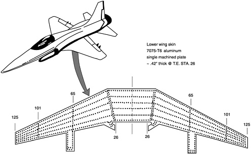
FIGURE A-10 Original lower wing skin design for the T-38 aircraft.
areas of the wing be cold worked. The near-term actions included (1) culling out all wings that had low fracture toughness material using a technique involving measuring the chemical composition of the material and correlating it with a previously established relationship between toughness and chemical composition and (2) using a trained team of NDE specialists to inspect the specific critical locations of the remaining wings using an ultrasonic technique at very frequent intervals.
Since the DADTA and the resulting recovery program in the late 1970s, the lower wing skins have been replaced with thicker skins made from 7075-T73 aluminum, the fastener holes and drain holes in high-stressed areas have been cold worked, and additional full-scale fatigue testing has been performed. Also, the T-38s have been replaced by F-16s in the Thunderbird demonstration team, and the Air Force no longer uses the T-38 in DACT use and has replaced LIF use with IFF use. However, the IFF use is still apparently quite severe. Based on the briefing the committee received on the T-38 structural status in November 1996, the aircraft continue to have more structural problems, and further design changes and full-scale fatigue testing are planned. Specific fatigue cracking problems were identified in the current wings and fuselage of the T-38:
Lower surface of the wing:
-
Wing main landing gear door land radius
-
cracking into main skin not repairable
-
modification of land plus special inspection required
-
future design change
-
-
Lower wing skin fastener holes
-
small critical crack sizes (0.2-0.4 in.)
-
oversizing and cold working required
-
future design change
-
-
Wing skin access panel holes
-
D panel; aileron access panel
-
cracking into main skin not repairable
-
stop drill/special inspection (temporary)
-
boron/epoxy doubler (temporary)
-
forcemate bushings under study by the ALC
-
-
Milled pockets on the lower wing skin
-
cracking in milled radius
-
not repairable
-
composite reinforcement under study by the ALC
-
future design change
-
-
Fuselage:
-
Upper cockpit longerons
-
hookslot cracking
-
small critical crack sizes
-
low inspection intervals
-
material change/redesign
-
force-wide modification in progress
-
In addition to the fatigue cracking problems, the San Antonio ALC identified the following SCC problems on the T-38:
Fuselage:
-
Cockpit longerons
-
upper and lower longerons
-
7075-T6 aluminum
-
cracking of the forward splice at fuselage station 284
-
inspect and repair (interim)
-
material change/redesign
-
force-wide modification of upper longerons
-
force-wide inspection/repair of lower longerons
-
-
Fuselage forgings
-
bulkheads at fuselage stations 325 and 362; formers at fuselage stations 332, 487, and 508
-
temporary repairs
-
material/design changes
-
force-wide modification of bulkhead at fuselage station 325
-
inspect and repair remaining changes
-
The following honeycomb deterioration problems were also noted:
-
Horizontal stabilizer
-
core corrosion attributable to water intrusion
-
improved bonding being implemented
-
-
Landing gear strut door
-
core corrosion attributable to water intrusion
-
superplastic formed/diffusion-bonded titanium redesign
-
current preferred spare
-
Based on the above, it is apparent that the San Antonio ALC will continue to face a major challenge to protect the safety and prolong the service life of the T-38 for another 25+years as indicated in Chapter 2 of this report. Most of the cracking problems noted are safety-of-flight concerns. As noted in Chapter 5, the committee recommends that this aircraft be given high priority in updating the DADTA and obtaining an improved estimate of economic service life.


