
| This page in the original is blank. |
Integration of Molecular and Macroscopic Scales in Tissue Engineering
Linda G. Griffith
Department of Chemical Engineering and Division of Bioengineering and Environmental Health Massachusetts Institute of Technology Cambridge, Massachusetts
Introduction
The field of tissue engineering has emerged over the past decade, driven by a diverse range of clinical needs for replacement of diseased or damaged tissue and for delivering genetically engineered cells to patients (Langer and Vacanti, 1993). Although many artificial prosthetic devices are available to replace connective tissues such as joints, heart valves, blood vessels, and breasts, few synthetic devices are able to perform adequately over the lifetime of a patient, and devices vary greatly in their abilities to completely replace all of the functions of native tissue. No long-term replacements are available for some connective tissues, including heart, small-diameter blood vessels, and skin. Clinical needs are even more dire for such organs as livers, which can now be replaced only by organ transplantation.
The goal of tissue engineers is to meet these clinical needs by creating living three-dimensional tissues and organs using cells obtained from readily available sources such as biopsy of a patient's own (autologous) tissue or foreign tissue that would be discarded after surgical procedures such as circumcision. In every case the approach is to break the donor material down to the level of individual cells and then coax the isolated cells into forming a tissue structure of the appropriate size and/or shape by using a physical "scaffold" to organize cells on a macroscopic scale and providing molecular cues to stimulate appropriate cell growth, migration, and differentiation.
The scientific foundation for this new field lies in molecular cell biology, which has enabled the identification of hundreds of molecules involved in controlling cellular behavior from the external environment and development of new methods for assessing cellular responses. The engineering challenges in
building on this science to meet clinical needs are at least twofold. The first challenge is to understand quantitatively how cells respond to these molecular signals and integrate multiple inputs to generate a given response—a significant challenge considering that the number of molecules identified so far represents only a fraction of the total that exist in the normal tissue environment. The second challenge is then to arrange cells in an appropriate three-dimensional configuration and present molecular signals in an appropriate spatial and temporal fashion so that the individual cells will grow and form the desired tissue structures—and do so in a way that can be carried out reproducibly, economically, and on a large scale. The specific examples described here are derived from work at the Massachusetts Institute of Technology and represent applications ranging from near term (less than one year) to very long term (more than 10 years).
Near Term—Connective Tissues
Tissues that have received the greatest attention from the commercial side—and thus are presumed to be feasible with current technology for near-term application in the clinic—include skin and cartilage. A common feature of these tissues is their relative avascularity and acellularity over dimensions important for tissue function, the ability to regenerate functional tissue from a single donor cell type, and the relative lack of cell-cell interactions in the normal tissue structure. Further, the cells in cartilage and skin grow readily in culture, allowing the number of cells from a single piece of donor tissue to be increased by several orders of magnitude. These factors make cartilage and skin highly attractive products for the emerging tissue engineering industry.
Among the many functions that cartilage serves in the human body, providing shape to such features as the outer ear and the nose is the least demanding from a tissue engineering perspective. Cartilage cells (chondrocytes) can readily be obtained by enzymatically digesting donor material to free cells from the extracellular matrix (ECM). Isolated chondrocytes placed in culture under appropriate conditions (e.g., in an agarose gel) exhibit a striking intrinsic ability to secrete ECM and form a stiff tissue similar to native cartilage. This property becomes useful for tissue engineering when the appropriate scaffold is used to direct tissue formation.
Our lab and many others have focused on synthetic bioresorbable polyesters in the polylactide/polyglycolide family as materials for scaffold construction in tissue engineering, as these materials have good mechanical properties, a long and favorable clinical record, are processable by solvent or thermal techniques, and break down by hydrolysis in body fluids to yield natural metabolites. In a collaboration initiated by a plastic surgeon at Boston Children's Hospital, we demonstrated that cartilage-like tissue in the shape of a human outer ear could be formed either in culture or by implanting beneath the skin a porous ear-shaped
scaffold seeded with chondrocytes (Vacanti et al., 1992). The polyesters were chosen so that the degradation in mechanical strength of the scaffold was commensurate with the gain in mechanical strength of the tissue being formed by chondrocyte-secreted ECM, allowing the implant to retain its shape over the two-month period required for cartilage to form.
This sort of approach is being commercialized, notably for replacement of dermis of skin in diabetic ulcers and burn victims (Cooper et al., 1991). These tissues lead the way in determining what kinds of manufacturing and regulatory procedures will be needed for more complex applications.
Long-Term—Vascularized Tissues
With few exceptions, tissues in the body are permeated by vascular networks to supply essential nutrients and regulatory factors. The distance between capillaries generally ranges from 20 to 200 microns, or about one to 10 cell diameters. The need for vascularity at almost the cellular scale is a major impediment to most cell-based approaches to tissue regeneration. Thus, tissues for which the microvascular network contributes strongly to overall tissue function, such as liver, have been more difficult to engineer and are correspondingly farther from clinical application. Highly vascularized tissues also tend to comprise several cell types arranged in a hierarchical structure, further complicating their reproduction by tissue engineering approaches. Cells derived from such tissues, such as hepatocytes from liver, often lose tissue-related functions when placed in culture; presumably, the hierarchy of structure also conveys a hierarchy of molecular control of cell behavior.
A place to start with such tissues is, then, understanding of the molecular signals that govern cell behavior. Virtually every aspect of cell behavior is governed at some level by interactions of transmembrane receptor molecules on the cell surface with ligands in the extracellular environment, and these complicated interactions are now being elucidated with the aid of engineering insights and analysis (Lauffenburger and Linderman, 1993). One example of a molecular control system is epidermal growth factor (EGF), which binds to the epidermal growth factor receptor (EGFR) to stimulate a diverse array of cell behaviors, including cell division. EGF was discovered in the early 1960s but has not yet entered clinical application despite many efforts to develop it and the wide range of effects it exerts under well-controlled in vitro conditions. It is inherently difficult to control local concentration of the peptide in vivo because of diffusive spread, cell uptake, and degradation of EGF. Further, when cells bind EGF, the EGF-EGFR complex is internalized and often degraded, leading to down regulation of receptors and attenuation of cellular responses. EGF is normally present in a soluble form, and some literature suggests that aspects of EGFR signaling can occur inside the cell after internalization. Nonetheless, we have shown that EGF retains biological activity when covalently tethered to the culture substrate
where it has mobility but is physically prevented from entering the cell or diffusing away; further, cell response can be tuned by the density of tethered EGF ligand presented (Kuhl and Griffith-Cima, 1996). In addition to applications in tissue engineering, the ability to manipulate ligand presentation by purely physical means is now becoming a powerful tool for fundamental understanding and control of receptor function, complementing tools derived from molecular cell biology. The use of molecularly designed polymers is becoming a new tool for probing cell behaviors.
Moving to the macroscopic level, issues of how groups of cells can self-organize is important. It is becoming more apparent that the molecular signals from ECM may at least partially govern cell behavior by measurable biophysical outcomes such as the relative magnitude of adhesive bonds (Lauffenburger and Horwitz, 1996). For example, the morphology of aggregates of hepatocytes in culture—spread or spheriodal—can be predicted on the basis of the relative magnitudes of cell-substrate adhesion strength and cell contractile forces, and the morphology of more complex structures obtained from mixed hepatocyte/endothelial cultures can also be predicted based on relative cell-cell and cell-substrate adhesion strengths (Powers et al., 1997). We are exploiting this self-organizing ability of cells to generate three-dimensional tissue with a perfused microvascular structure in vitro starting from dispersed cells and a scaffold of precisely defined architecture and surface chemistry. Our initial focus is on trying to recreate the smallest functional unit in a tissue, the capillary bed, which has dimensions of 0.1 to 0.8 mm depending on the tissue and is ~0.8 mm for liver. We have developed and implemented new materials processing techniques to create scaffolds for this purpose, a technique that will allow integration of molecular cues, such as tethered EGF, with macroscopic signals (Griffith et al., 1997).
On the in vivo therapeutic side, our ultimate aim is to create a liver that can be transplanted directly into the portal vein of a patient beginning with a complex hierarchical scaffold seeded with cells. To create scaffolds with this high degree of complexity, we have implemented a solid free-form fabrication (SFF) technique, the 3 Dimensional Printing (3DPTM) process. In SFF techniques, devices are built as a series of thin sequential layers. We have adapted the original 3DPTM process, developed for fabrication of ceramics and metals, to a range of polymeric and composite organic/inorganic materials important in tissue engineering and drug delivery. This technology is currently being commercialized.
In addition to the huge clinical needs for vascularized tissues, in vitro models of vascularized human tissues are desperately needed in the pharmaceuticals industry for determining the effects of drugs on humans and for basic research into disease states and development. Generation of tissue that can be controllably perfused in vitro and maintained in culture for extended periods will enhance virtually every effort to study tissue functions in vitro. We are implementing silicon microfabrication technology to create a miniature "liver on a chip" to allow rapid screening of drugs and other compounds.
References
Cooper, M. L., J. F. Hansbrough, R. L. Spielvogel, R. Cohen, R. L. Bartel, and G. Naughton. 1991. In vivo optimization of a living dermal substitute employing cultured human fibroblasts on a biodegradable polyglycolic acid or polyglactin mesh. Biomaterials 12(2):243-248.
Griffith, L., B. Wu, M. J. Cima, B. Chaignaud, and J. P. Vacanti. 1997. In vitro organogenesis of liver tissue. Annals of the New York Academy of Sciences 831(December 31):382-397.
Kuhl, P. R., and L. G. Griffith-Cima. 1996. Tethered epidermal growth factor as a paradigm for growth factor-induced stimulation from the solid phase. Nature Medicine 2(9):1022-1027.
Lauffenburger, D. A., and A. F. Horwitz. 1996. Cell migration: A physically integrated molecular process. Cell 84(3):359-369.
Lauffenburger, D. A., and J. L. Linderman. 1993. Receptors: Models for Binding, Trafficking, and Signaling. New York: Oxford University Press.
Langer, R., and J. P. Vacanti. 1993. Tissue engineering. Science 260(5110):920-926.
Powers, M. J., R. E. Rodriguez, and L. G. Griffith. 1997. Cell-substratum adhesion strength as a determinant of hepatocyte aggregate morphology. Biotechnology and Bioengineering 53(4): 415-426.
Vacanti, C. A., L. G. Cima, D. Rodkowski, and J. Upton. 1992. Tissue engineered growth of new cartilage in the shape of a human ear using synthetic polymers seeded with chondrocytes. Pp. 323-330 in Tissue-Inducing Biomaterials, Materials Research Society Symposium Proceedings, Vol. 252, L. G. Cima and E. S. Ron, eds. Pittsburgh, Pa.: Materials Research Society.
Artificial Proteins: Bridging the Gap Between Natural and Synthetic Macromolecular Materials
David A. Tirrell
Division of Chemistry and Chemical Engineering California Institute of Technology Pasadena, California
How should one approach the engineering of macromolecular materials that combine the very different virtues of natural and synthetic polymers? Natural polymers, especially proteins and nucleic acids, serve as selective catalysts and as efficient information storage devices, while their synthetic counterparts (polyethylene, polypropylene, and so on) dominate modern materials technology because of their excellent mechanical, barrier, and processing behaviors (Rodriguez, 1996). The molecular architectural features that underlie these disparate patterns of behavior are strikingly different: proteins and nucleic acids are characterized by precisely defined chain lengths and sequences, whereas synthetic polymeric materials consist of complex mixtures of chain molecules in which length, sequence, and stereochemistry (molecular shape) vary widely from chain to chain.
Template Polymerization
The architectural differences between natural and synthetic polymers arise from differences in the nature of the polymerization processes that lead to each class of materials. Proteins and nucleic acids are made via "template polymerizations" in which each copy of the polymer chain is assembled on a nucleic acid template that dictates the length and sequence of each product molecule. Synthetic polymers, on the other hand, arise from statistical polymerization processes in which the relative rates of competing initiation, propagation, and termination steps determine the average chain structure as well as the distribution of structures formed. It is not surprising that these classes of macromolecules behave so differently; it is difficult to imagine, for example, how one could store genetic
information in a population of chains in which product structure cannot be traced back to the structure of a precursor molecule.
The power of template polymerizations has been recognized by polymer materials scientists for decades, and the literature reports many attempts to use templates to control polymer structure and polymerization rate (Tan, 1989). These attempts have met with near total failure. To be sure, the addition of a template to a polymerizing mixture is often accompanied by changes in product structure or reaction rate, but the observed changes are rarely predictable and the causes of change rarely clear. These results highlight the difficulty of de novo design of molecular templates for control of chemical synthesis.
Nucleic Acid Templates
An alternative approach to this problem acknowledges the difficulty of template design and exploits the known success of nucleic acids as templates for protein synthesis. Recombinant DNA methods now allow cells to be outfitted with genes that encode any desired sequence of amino acids, even if that sequence bears no relation to any natural protein. It has also been demonstrated that the protein biosynthetic apparatus can accommodate monomers other than the 20 amino acids normally used to build cellular proteins. The materials engineer is thus presented with an important new opportunity—that of designing polymeric materials of precisely controlled architectures without sacrificing the versatility characteristic of synthetic polymers. Thus, it may indeed be possible to combine the virtues of natural and synthetic macromolecular materials.
Artificial Proteins
Two complementary approaches to this problem have been explored over the past several years. The first uses recombinant DNA methods (or in some cases organic chemical synthesis) to prepare variants of natural structural proteins such as silk, elastin, or marine adhesives. Here biology serves very directly as a guide to new materials science in that the investigator makes relatively minor changes in polymer structure in the hope that the useful properties of the natural material can be preserved in a simplified variant that is more readily prepared. The most encouraging successes of this approach have been reported for analogs of elastin, a protein that—as its name implies—contributes to the elastic properties of various tissues. Simple elastin analogs have been shown to exhibit excellent mechanical properties and have been engineered to change shape in response to a variety of chemical and physical signals (Urry, 1993). Efforts to develop such materials for surgical and pharmaceutical applications are under way.
The second approach starts from the perspective of the polymer materials scientist and involves de novo design of artificial proteins. Protein structure and
function continue to enter into the design process, and in some cases natural structural motifs are exploited, but the designs also embrace ideas drawn from the science and technology of synthetic polymeric materials. Because the materials of interest often differ substantially from any known natural proteins, this method tests the capacity of the biosynthetic apparatus to make novel and diverse macromolecular structures. The messenger RNA template that guides protein synthesis in this approach is derived not from any natural gene but rather from an artificial gene that specifies the sequence of amino acids dictated by the materials design process. The template polymerization that nature uses to build cellular proteins is co-opted by the materials engineer for his or her own purposes.
This approach has been used to prepare several new families of artificial proteins of interest in materials science and engineering. Early experiments addressed the concept of "encoded self-assembly," in which the artificial gene is designed to control not only the covalent structure of the chain but also the manner in which polymer chains assemble into larger-scale aggregates such as crystals or liquid crystals. By designing periodic polypeptide sequences, for example, one can control crystal dimensions and surface chemistry in ways that are not available to conventional polymeric materials (Krejchi et al., 1994). In similar fashion, by making populations of uniform rod like polymers, one gains access to novel liquid crystal phases in polymer solutions and films (Yu et al., 1997).
New Building Blocks for Artificial Proteins
Perhaps the most ambitious use of artificial genes to direct polymer synthesis involves the incorporation of amino acids other than the 20 normally used by cells to build proteins. It has been known for many years that analogs of some of the "canonical" amino acids can be activated and charged to transfer RNAs for incorporation into the growing protein chain, and recent experiments have shown that substitution by analogs can effect important changes in materials properties. Replacement of hydrogen by fluorine is particularly useful in this regard; hydrogen and fluorine differ little in size, making substitution straightforward in most instances. At the same time, fluoropolymers such as Teflon exhibit valuable surface properties that are markedly different from those of their hydrocarbon relatives. Other successful examples include amino acids bearing thienyl, alkenyl, and alkynyl side chains (van Hest and Tirrell, 1998).
Chimeric Artificial Proteins
Finally, one can combine the two approaches described above to create "chimeric" or "hybrid" proteins that include both natural and artificial polypeptide sequences. This may in fact be the simplest answer to the question posed at the beginning of this paper; the natural domain of the chimera performs its
normal function while the artificial domain confers the needed materials properties such as strength, toughness, or adhesion to surfaces. In a recent example, so-called leucine-zipper peptide domains were attached to the ends of a water-soluble polypeptide to create triblock chimeric proteins in which the leucine zippers control polymer-polymer interactions in a manner that leads to reversible gelatin of the protein solution in response to changes in pH or temperature (Petka et al., 1998).
References
Krejchi, M. T., E. D. T. Atkins, A. J. Waddon, M. J. Fournier, T. L. Mason, and D. A. Tirrell. 1994. Chemical sequence control of B-sheet assembly in macromolecular crystals of periodic polypeptides. Science 265:1427-1432.
Petka, W. A., J. L. Harden, K. P. McGrath, D. Wirtz, and D. A. Tirrell. 1998. Reversible hydrogels from self-assembling artificial proteins. Science 281:389-392.
Rodriguez, F. 1996. Principles of Polymer Systems, 4th ed. Washington, D.C.: Taylor & Francis.
Tan, Y. Y. 1989. Pp. 245-259 in Comprehensive Polymer Science: Template Polymerization. Oxford, England: Pergamon Press.
Urry, D. W. 1993. Molecular machines: How motion and other functions of living organisms can result from reversible chemical changes. Angewandte Chemie. International Edition in English 32:819-841.
van Hest, J. C. M., and D. A. Tirrell. 1998. Efficient introduction of alkene functionality into proteins in vivo. FEBS Letters 428:68-70.
Yu, S. M., V. Conticello, C. Kayser, M. J. Fournier, T. L. Mason, and D. A. Tirrell. 1997. Smectic ordering in solutions and films of a rod-like polymer owing to monodispersity of chain length. Nature 389:167-170.
Biomedical Imaging Using Optical Coherence Tomography
James G. Fujimoto
Department of Electrical Engineering and Computer Science and Research Laboratory of Electronics Massachusetts Institute of Technology Cambridge, Massachusetts
Abstract
Optical coherence tomography (OCT) is a new technology for performing high-resolution cross-sectional imaging. OCT functions as a type of optical biopsy that provides cross-sectional images of tissue structure on the micron scale. In combination with catheters and endoscopes, OCT can perform internal body imaging. OCT is a powerful imaging technology for medical diagnostics because, unlike conventional histopathology, which requires removal of a tissue specimen and processing for microscopic examination, OCT can provide images of tissue in situ and in real time.
Introduction
OCT is a recently developed optical imaging technique that performs high-resolution, cross-sectional imaging of microstructures in biological systems (Huang et al., 1991). OCT is analogous to ultrasound B mode imaging except that it uses light instead of sound. OCT performs imaging by using low-coherence interferometry to measure the optical backscattering of tissue as a function of echo delay and transverse position. The resulting two-dimensional dataset can be displayed as a gray scale or false color image.
OCT was originally developed and applied by our group for tomographic diagnostics in ophthalmology. OCT can provide images of the retina with resolutions of 10 µm, one order of magnitude higher than conventional ultrasound (Hee et al., 1995). Working in collaboration with the New England Eye Center and MIT's Lincoln Laboratory, we developed a clinical prototype OCT instrument for ophthalmic diagnosis. Several thousand patients have been examined
to date (Hee et al., 1995; Puliafito et al., 1995a,b). The technology has been transferred to industry, and a commercial product was introduced into the ophthalmic market in 1996. More recently, advances in OCT imaging have enabled imaging to be performed in nontransparent tissues, thus enabling its application in a wide range of possible medical specialties (Brezinski et al., 1996; Fujimoto et al., 1995; Schmitt et al., 1994, 1995). Imaging depth is limited by optical attenuation due to scattering and absorption. However, in most tissues, imaging 2 to 3 mm deep can be achieved. OCT has been applied in vitro to image arterial pathology where it can differentiate plaque morphology with superior resolution to ultrasound (Brezinski et al., 1996). Imaging studies have also been performed in vitro to investigate applications in gastroenterology, urology, gynecology, surgery, and neurosurgery (Brezinski et al., 1997a,b; Tearney et al., 1997b,c). OCT has been applied in vivo to image developing biological specimens (African frog, leopard frog, and zebrafish tadpoles and embryos). For applications in developmental biology, OCT can permit the repeated imaging of developing morphology without the need to sacrifice specimens (Boppart et al., 1996).
OCT is a promising and powerful medical imaging technology because it can permit real-time in situ visualization of tissue microstructure without the need to excisionally remove and process a specimen, as in conventional biopsy and histopathology. The concept of "nonexcisional optical biopsy" provided by OCT and the ability to visualize tissue morphology in real time under operator guidance can be used both for diagnostic imaging and to guide surgical intervention. Coupled with catheter, endoscopic, or laparoscopic delivery, OCT holds the promise of having a widespread impact on medicine, ranging from improving the screening and diagnosis of cancer to enabling new microsurgical and minimally invasive surgical procedures.
Principles of Operation and Technology
OCT is analogous to ultrasound imaging but is based on optical ranging and the high-resolution, high-dynamic-range detection of backscattered light. In contrast to ultrasound, because the velocity of light is extremely high, the echo time delay of reflected light cannot be measured directly. One method for measuring the time delay of light is to use low-coherence interferometry or optical coherence domain reflectometry. Low-coherence interferometry was first developed for measuring reflections in fiber optics and optoelectronic devices and was first demonstrated in ophthalmology for measurements of axial eye length and corneal thickness (Fercher et al., 1988; Hitzenberger, 1991; Takada et al., 1987). Low-coherence interferometry uses heterodyne detection of light backscattered from the sample. Interference of the light reflected from the sample arm and reference arm of a Michelson interferometer (see Figure 1) can occur only when the optical path lengths of the two arms match to within the coherence length of
Figure 1
OCT measures the echo time delay of reflected light by using low-coherence interferometry. The system is based on a Michelson-type interferometer. Reflections or backscattering from the object being imaged are correlated with light, which traverses a reference path.
the optical source. As the reference arm optical path length is scanned, backscattering sites within the sample arm are localized.
Figure 2 is a schematic illustrating how OCT performs cross-sectional imaging. The optical beam is focused into the object being imaged, and the echo time delay and intensity of the backscattered light are measured to yield an axial backscattering profile. The incident beam is then scanned in the transverse direction, and the axial backscattering is measured at several transverse positions to yield a two-dimensional dataset. This dataset represents the backscattering or back reflection through a cross-section of the object being imaged and can be displayed as a gray scale or false color image.
The axial resolution in OCT images is determined by the coherence length of the light source. The interference signal detected at the output port of the interferometer is the electric field autocorrelation of the source. The coherence length is the spatial width of the field autocorrelation. The envelope of the field autocorrelation is equivalent to the Fourier transform of its power spectrum.
Figure 2
Cross-sectional images are constructed by performing measurements of the echo time delay of light at different transverse positions. The result is a two-dimensional dataset that represents the backscattering in a cross-sectional plane of the tissue.
Thus, the width of the autocorrelation function, or the axial resolution, is inversely proportional to the width of the power spectrum. For a source with a Gaussian spectral distribution, the axial resolution Δz is given by: Δz = (2ln2/π)(λ2/Dl), where Δz and Dl are the full widths at half maximum of the autocorrelation function and power spectrum, respectively, and λ is the source central wavelength. Thus, broad-bandwidth optical sources are required to achieve high axial resolution. The transverse resolution achieved with an OCT imaging system is determined by the focused spot size in analogy with conventional microscopy. The transverse resolution is given by: Δx = (4λ/π)(f/d), where d is the spot size on the objective lens and f is its focal length. High-transverse resolution can be obtained by using a large numerical aperture and focusing the beam to a small spot size.
OCT can be implemented using fiber optic technology. Figure 3 shows a schematic of an OCT system that uses a fiber optic Michelson-type interferometer. A low coherence light source is coupled into the interferometer and the interference at the output is detected with a photodiode. One arm of the interferometer emits a beam that is directed and scanned on the object being imaged, while the other arm of the interferometer is a reference arm with a scanning delay line. Because OCT uses fiber optics, it can easily be interfaced to a wide range of optical instruments.
For research applications, short-pulse lasers are used as light sources for
Figure 3
Schematic of OCT instrument based on fiber optic implementation of a Michelson interferometer. One arm of the interferometer is interfaced to the measurement instrument, and the other arm has a scanning delay line. The system shown is configured for high-speed catheter-endoscope-based imaging.
OCT imaging because they have extremely short coherence lengths and high-output powers, thereby enabling high-resolution, high-speed imaging. For clinical applications, compact superluminescent diodes or semiconductor-based light sources can be used. The laser source for many of our studies was a short-pulse Cr4+:Forsterite laser, which operates near 1,300 nm and achieves an axial resolution of 5 to 10 µm with a signal-to-noise ratio of 110 dB (Boppart et al., 1998). A rapidly scanning optical delay line based on a grating phase control device, similar to that used in ultrafast optics, is used for delay scanning (Tearney et al., 1997a). The grating-phase control device is attractive because it permits the phase and group velocity of the scan to be independently controlled and achieves extremely high scan speed. Images of 250 to 500 transverse pixels can be produced at four to eight frames per second. Future systems will operate at video rates.
Applications
OCT is a promising and powerful medical imaging technique because it can permit in situ and real-time visualization of tissue microstructure with resolutions that are one to two orders of magnitude higher than ultrasound. OCT was initially applied for imaging in the eye, and to date, has had the broadest clinical impact in ophthalmology. Figure 4 shows an example of an OCT image of the retina of a human subject (Hee et al., 1995). This image was taken at a 10-µm resolution and allows the detailed structure of the retina to be differentiated. The retinal thickness can be easily measured as well as the retinal nerve fiber layer, which is visible as a highly backscattered layer. Clinical studies in ophthalmology show that OCT is especially promising for the diagnosis and monitoring of
Figure 4
OCT image of the human retina papillary-macular axis illustrating the ability to discriminate structural morphology in vivo. The highly backscattered retinal nerve fiber layer and choriocapillaris appear red. The optic disk as well as several of the retinal layers are observed. Source: Reprinted with permission from the American Medical Association (Hee et al., 1995).
such diseases as glaucoma and macular edema associated with diabetic retinopathy, where it provides quantitative information on disease progression (Puliafito et al., 1995b). In many cases OCT has the ability to detect and diagnose early stages of disease before physical symptoms and loss of vision occur.
OCT can also be used for a variety of applications in internal medicine and internal body imaging of scattering tissues. Although the image penetration depth is limited to a few millimeters, this scale is comparable to the depth over which many biopsies are performed and many diagnostically important changes in tissue morphology occur near tissue or organ surfaces. OCT can resolve changes in architectural morphology that are important for diagnosis of diseases such as early neoplastic changes. Figure 5 shows an example of OCT images of human gastrointestinal tissues in vitro. These images were performed at 15-µm resolution using a 1,300-nm wavelength. The top image shows the structure of the normal esophageal mucosal tissue, which is characterized by a horizontally organized squamous epithelial structure. The middle image shows the structure of the normal intestinal mucosal tissue, which has a vertically organized columnar epithelial structure. Even at modest resolutions of 15 µm, the differences between the architectural morphology of these tissue types is evident. The bottom image shows an ampullary carcinoma. The carcinoma is evident in the left one-third of the image and is characterized by a loss of the glandular organization of the tissue. Normal bowel is seen at the right one-third of the image and is characterized by vertically organized columnar epithelial structure. The center part of the image shows a progressive disorganization and loss of structure.
Figure 5
In vitro images of gastrointestinal tissues and pathology, including normal human esophagus, colon, and ampullary carcinoma. These images illustrate the ability of OCT to discriminate architectural morphology.
Changes in architectural morphology such as these can be used for the screening and diagnosis of early neoplastic changes. Conventional excisional biopsy often suffers from high false-negative rates because the biopsy process relies on sampling tissue and the diseased tissues can easily be missed. OCT might be used to identify suspect lesions and guide excisional biopsy in order to reduce the false-negative rates. In future applications, when sufficient clinical data are available, OCT might be used directly for diagnosis.
For OCT imaging in internal organ systems, it is necessary to develop optical delivery technologies (Boppart et al., 1997; Tearney et al., 1996). Using fiber optics, a catheter-endoscope with an outer diameter of 2.9 French or 1.0 mm has been constructed. Figure 6 shows a schematic of an OCT catheter-endoscope. A single-mode optical fiber runs the length of the catheter, and the distal end consists of a GRIN lens and a microprism to direct the OCT beam radially. The fiber and distal optics are rotated so that the OCT beam scans an angular, radar-like, pattern and image cross-sectionally through internal organs.
The catheter-endoscope OCT system enables the acquisition of in vivo images of internal organ systems. Figure 7 shows an example of a catheter-endoscope OCT image of the esophagus of a rabbit in vivo. In vivo imaging of the pulmonary tract, gastrointestinal tract, and urinary tract as well as arterial imaging have been performed. These studies demonstrate the feasibility of performing OCT imaging of internal organ systems and suggest the possibility of its application clinically (Tearney et al., 1997a). Other research groups as well as ours are currently beginning OCT imaging studies in patients, and we expect results to be published shortly.
Figure 6
OCT catheter for transverse intraluminal imaging. A single-mode fiber lies within a rotating flexible speedometer cable enclosed in a protective plastic sheath. The distal end focuses the beam at 90 degrees from the axis of the catheter.
Source: Reprinted with permission from Optical Society of America (Tearney et al., 1996).
Figure 7
OCT image of esophageal structures of New Zealand White rabbit in vivo performed by using prototype transverse scanning OCT catheter and high-speed imaging system. Image acquisition time was 250 ms per image for 300-pixel radial image.
The development of high-resolution OCT is also an important area of active research. Increasing resolutions to the cellular and subcellular levels are important for many applications, including the diagnosis of early neoplasias. One of the keys to achieving high resolution is the use of short-pulsed lasers to obtain short coherence length. High-resolution OCT imaging has been demonstrated in vivo in developmental biology specimens. Figure 8 shows an example of high-resolution OCT images of a Xenopus laevis (African frog) tadpole (Boppart et al., 1998). The OCT beam was focused to a 9-µm diameter spot (100-µm confocal parameter). A short-pulse Cr4+:Forsterite laser that operates near 1,300 nm was used as the light source for these measurements. The free-space axial resolution was 5.1 µm. Assuming an average index of 1.35 for these specimens, the in vivo axial resolution was ~ 3.8 µm. In developmental biology the ability to image subcellular structure can be an important tool for studying mitotic activity and cell migration, which occur during development. The extension of these results to humans has important implications for the diagnosis of early neoplasias. Many of these diseases are manifest by changes that occur on cellular and subcellular levels.
The development of high-resolution high-speed OCT technology as well as OCT-compatible catheter-endoscopes represents enabling steps for many OCT imaging applications, including future endoscopic clinical applications. OCT is
Figure 8
High-resolution OCT images of a Xenopus laevis (African frog) tadpole in vivo. (A) Mesenchymal cells immediately following cell division with two daughter cells (arrow). Cell membranes and individual cell nuclei are apparent. (B) Melanin-laden neural crest cells, which migrate during development.
a powerful technique for optical biopsy because it can perform micron-scale imaging of cellular and architectural morphology in situ and in real time. Imaging information is available in real time without the need for excision and histological processing of a specimen. The capability to perform rapid in situ imaging can be used in a variety of clinical scenarios, including (1) to guide conventional biopsy and reduce false-negative rates due to sampling errors, (2) to perform
imaging of tissue microstructure in situations where conventional excisional biopsy would be hazardous or impossible, and (3) to guide surgical or microsurgical intervention. More research remains to be done, and numerous clinical studies must be performed to determine in which clinical situations OCT can play a decisive role. The unique capabilities of OCT imaging suggest that it has the potential to have a significant impact on the diagnosis and clinical management of many diseases.
Acknowledgments
This work was performed in collaboration with Mark Brezinski of the Harvard Medical School and Massachusetts General Hospital. The contributions of Steve Boppart, Brett Bouma, Gary Tearney, Juergen Herrmann, Wolfgang Drexler, Xingde Li, and Costas Pitris are gratefully acknowledged. This research is supported in part by National Institutes of Health contracts NIH-9-ROI-CA75289-01 and NIH-9-ROI-EY11289-13 and the Medical Free Electron Laser Program, Office of Naval Research contract N000014-97-1-1066.
References
Boppart, S. A., M. E. Brezinski, B. Bouma, G. J. Tearney, and J. G. Fujimoto. 1996. Investigation of developing embryonic morphology using optical coherence tomography. Developmental Biology 177(1):54-63.
Boppart, S. A., B. E. Bouma, C. Pitris, G. J. Tearney, J. G. Fujimoto, and M. E. Brezinski. 1997. Forward-imaging instruments for optical coherence tomography. Optics Letters 22(21): 1618-1620.
Boppart, S. A., B. E. Bouma, C. Pitris, J. F. Southern, M. E. Brezinski, and J. G. Fujimoto. 1998. In vivo cellular optical coherence tomography imaging. Nature Medicine 4(7):861-865.
Brezinski, M. E., G. J. Tearney, B. E. Bouma, J. A. Izatt, M. R. Hee, E. A. Swanson, J. F. Southern, and J. G. Fujimoto. 1996. Optical coherence tomography for optical biopsy: Properties and demonstration of vascular pathology. Circulation 93(6): 1206-1213.
Brezinski, M. E., G. J. Tearney, S. A. Boppart, E. A. Swanson, J. F. Southern, and J. G. Fujimoto. 1997a. Optical biopsy with optical coherence tomography: Feasibility for surgical diagnostics. Journal of Surgical Research 71(1):32-40.
Brezinski, M. E., G. J. Tearney, N. J. Weissman, S. A. Boppart, B. E. Bouma, M. R. Hee, A. E. Weyman, E. A. Swanson, J. F. Southern, and J. G. Fujimoto. 1997b. Assessing atherosclerotic plaque morphology: Comparison of optical coherence tomography and high frequency intravascular ultrasound . Heart 77(5):397-403.
Fercher, A. F., K. Mengedoht, and W. Werner. 1988. Eye-length measurement by interferometry with partially coherent light. Optics Letters 13(3):186-188.
Fujimoto. J. G., M. E. Brezinski, G. J. Tearney, S. A. Boppart, B. E. Bouma, M. R. Hee, J. F. Southern, and E. A. Swanson. 1995. Biomedical imaging and optical biopsy using optical coherence tomography. Nature Medicine 1(9):970-972.
Hee, M. R., J. A. Izatt, E. A. Swanson, D. Huang, C. P. Lin, J. S. Schuman, C. A. Puliafito, and J. G. Fujimoto. 1995. Optical coherence tomography of the human retina. Archives of Ophthalmology 113(3):325-332.
Hitzenberger, C. K. 1991. Measurement of the axial eye length by laser Doppler interferometry. Investigative Ophthalmology and Visual Science 32(3):616-624.
Huang, D., E. A. Swanson, C. P. Lin, J. S. Schuman, W. G. Stinson, W. Chang, M. R. Hee, T. Flotte, K. Gregory, C. A. Puliafito, and J. G. Fujimoto. 1991. Optical coherence tomography. Science 254(5035): 1178-1181.
Puliafito, C. A., M. R. Hee, C. P. Lin, E. Reichel, J. S. Schuman, J. S. Duker, J. A. Izatt, E. A. Swanson, and J. G. Fujimoto. 1995a. Imaging of macular disease with optical coherence tomography. Ophthalmology 102(2):217-229.
Puliafito, C.A., M. R. Hee, J. S. Schuman, and J. G. Fujimoto. 1995b. Optical Coherence Tomography of Ocular Diseases. Thorofare, N.J.: Slack, Inc.
Schmitt, J. M., A. Knuttel, M. Yadlowsky, and A. A. Eckhaus. 1994. Optical coherence tomography of a dense tissue: Statistics of attenuation and backscattering. Physics in Medicine and Biology 39(10): 1705-1720.
Schmitt, J. M., M. J. Yadlowsky, and R. F. Bonner. 1995. Subsurface imaging of living skin with optical coherence microscopy. Dermatology 191(2):93-98.
Takada, K., I. Yokohama, K. Chida, and J. Noda. 1987. New measurement system for fault location in optical waveguide devices based on an interferometric technique. Applied Optics 26(9): 1603-1606.
Tearney, G. J., S. A. Boppart, B. Bouma, M. E. Brezinski, N. J. Weissman, J. F. Southern, and J. G. Fujimoto. 1996. Scanning single mode catheter/endoscope for optical coherence tomography. Optics Letters 21(7):543-545.
Tearney, G. J., M. E. Brezinski, B. E. Bouma, S. A. Boppart, C. Pitris, J. F. Southern, and J. G. Fujimoto. 1997a. In vivo endoscopic optical biopsy with optical coherence tomography. Science 276(5321):2037-2039.
Tearney, G. J., M. E. Brezinski, J. F. Southern, B. E. Bouma, S. A. Boppart, and J. G. Fujimoto. 1997b. Optical biopsy in human gastrointestinal tissue using optical coherence tomography. American Journal of Gastroenterology 92(10): 1800-1804.
Tearney, G. J., M. E. Brezinski, J. F. Southern, B. E. Bouma, S. A. Boppart, and J. G. Fujimoto. 1997c. Optical biopsy in human urologic tissue using optical coherence tomography. Journal of Urology 157(5):1915-1919.
Confocal Reflectance Microscopy: Diagnosis of Skin Cancer Without Biopsy?
Milind Rajadhyaksha
Lucid, Inc., Henrietta, New York and Massachusetts General Hospital, Boston
Introduction
X-ray tomography, magnetic resonance imaging, and ultrasound are noninvasive biomedical imaging modalities commonly used in the clinic. These imaging modalities have resolutions of 10 to 1,000 µm, which allows assessment of the gross (macro) structure of living tissue but not its detailed cellular and nuclear microstructures. Clinical assessment of cellular and nuclear microstructure (histology) requires a resolution of 0.1 to 10 µm and is performed by conventional optical microscopy. Conventional microscopy is invasive: one must remove (biopsy) the tissue, fix or freeze, excise into thin sections (typically 5-µm slices), and stain with dyes to enhance contrast. Biopsies destroy the site being investigated and prevent subsequent imaging of dynamic events. Tissue processing introduces artifacts and is expensive and time consuming. An alternative technique that potentially avoids biopsies or tissue processing is confocal reflectance microscopy. A confocal microscope can noninvasively image cellular and nuclear microstructures in thin sections within living tissue with high resolution and contrast (Pawley, 1995; Webb, 1996).
Confocal reflectance microscopy offers a noninvasive window into living human tissue for basic and clinical research. No biopsy, processing, or staining of tissue is necessary. Imaging is based on the detection of backscattered light with contrast due to naturally occurring refractive index variations of tissue microstructures. Between 1991 and 1996, scientists at L'Oreal in France demonstrated confocal imaging of living human skin with a white-light tandem scanning microscope (Bertrand and Corcuff, 1994; Corcuff et al., 1993, 1996; Corcuff and Leveque, 1993; New et al., 1991). In 1995 we developed a confocal scanning laser microscope for real-time imaging of human tissues (Rajadhyaksha et
al., 1995). Cellular and nuclear microstructures in normal human skin and skin cancers, and dynamic events such as circulating blood flow, the response of skin to ultraviolet light, and wound healing were investigated (Rajadhyaksha and Zavislan, 1998).
Motivation
Dermatologists spend a large portion of their time diagnosing skin lesions or "moles" (see Figure 1). These lesions are of various shapes, sizes, and colors. Clinical screening is initially performed with either the naked eye or a low-power microscope (i.e., magnifying glass). Often the initial screening is not reliable because different cancers may look alike on the skin surface, and clinical pictures (such as Figure 1) do not reveal the subsurface tissue cellular and nuclear microstructures. Consequently, the accuracy of clinical screening of skin cancers is low; for example, the success rate for detecting melanomas (the most serious and potentially fatal skin cancer) is only 60 to 90 percent, depending on the dermatologist's expertise. Biopsies are almost always required for an accurate diagnosis. Of the approximately 3 million biopsies performed annually in the United States, 60 to 80 percent turn out to be noncancerous and therefore could have been avoided. Confocal reflectance microscopy offers dermatologists a noninvasive real-time imaging diagnostic tool that may potentially be useful for either screening lesions prior to biopsy or for diagnosis without biopsy.
Principles of Confocal Microscopy
Confocal microscopy is one of those wonderful ideas that seem obvious but only after someone else (Minsky, 1957) has intuitively figured it out. A confocal
Figure 1
Clinical appearance of a melanoma, which is the most serious and potentially fatal skin cancer. Clinical screening is based on this low-magnification, low-resolution photograph, which does not reveal subsurface tissue cellular and nuclear microstructures. By comparison, the microstructure of this melanoma can be noninvasively visualized with confocal microscopy (Figure 6b); thus, confocal imaging can potentially improve the accuracy of clinical screening.
Figure 2
A confocal microscope can noninvasively image a thin plane (section) that is in focus in a scattering object. This is called optical sectioning. The small aperture in front of the detector collects only the light that is in focus (solid lines) while spatially filtering light that is out of focus (dotted lines). Although the light is shown to penetrate the object, imaging of living tissue is based on the detection of backscattered light (Figure 3). Source: Reprinted with permission from Mediscript Ltd. (Rajadhyaksha and Zavislan, 1998).
microscope (see Figure 2) consists of a "point" or small source of light that illuminates a "point" or small spot within an object, and the illuminated spot is then imaged onto a detector through a "point" or small aperture. The source, illuminated spot, and detector aperture are placed in optically conjugate focal planes, so we say they are "confocal" to each other. The detector aperture size is matched to the illuminated spot size through the intermediate optics. Because we illuminate a small spot and detect through a small aperture, we image only the plane that is in focus within the object. Light originating in planes that are out of focus is spatially filtered from entering the detector. A confocal microscope thus allows noninvasive imaging of a thin plane (section) within a scattering object with high axial (and also lateral) resolution; because we reject all the light that is not in focus, the image has high contrast. This is known as "optical sectioning."
The arrangement in Figure 2 shows that only a single spot may be illuminated and imaged at a time. Imaging a single point is often not useful in medicine. To view the whole object, one must then scan the illuminated spot over the desired field of view. We illuminate the object point by point in a two-dimensional raster and then create the image correspondingly point by point. Scanning may be done by either moving the specimen relative to a stationary illumination beam (object scanning) or by moving the beam relative to a stationary specimen (beam scanning). For imaging of human beings, beam scanning is obviously easier than object scanning. Although the configuration in Figure 2 shows the light transmitting through the object, imaging of living human tissue is based on
Figure 3
Confocal imaging is based on the detection of backscattered light, with the illumination source and detector being on the same side of the human being.
Source: Reprinted with permission from Mediscript Ltd. (Rajadhyaksha and Zavislan, 1998).
the detection of backscattered light (see Figure 3) such that the illumination source and the detector are on the same side of the human being.
Development of Confocal Scanning Laser Microscopes
Laboratory Prototype
At Wellman Laboratories, Massachusetts General Hospital (MGH), we built a video-rate confocal scanning laser microscope (CSLM) for noninvasive imaging of living human tissue (Rajadhyaksha et al., 1995). Figure 4 shows the optical design of our prototype CSLM. Any laser and wavelength may be used for illumination; we use near-infrared 800- to 1,064-nm wavelengths. Near-infrared wavelengths are preferred to visible wavelengths because of reduced scattering and absorption and hence deeper penetration into tissue (Anderson and Parrish, 1981). The collimated laser beam is scanned in the fast (X) direction with a rotating polygon mirror and in the slow (Y) direction with an oscillating galvanometric mirror. The scanning is at standard video rates of 15.734 kHz along X and 60 Hz along Y, so that the images can be displayed in real time on a television monitor. Two fields at 60 Hz are interlaced to produce a frame rate of 30 Hz, which is the standard for television in the United States. The X and Y scanning produces a raster of laser beam spots in the back focal plane of the objective lens, which, when demagnified by the objective lens, defines the field of view at the tissue. For 20x to 100x objective lenses that we usually use, the field of view is 800 to 160 µm. The raster illuminates an XY plane within the tissue through a standard microscope objective lens. The XY plane is a horizontal plane parallel to the surface of the tissue, and the Z axis (optical axis of the
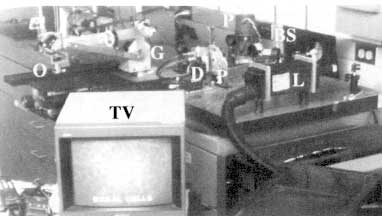
Figure 4
Laboratory-prototype confocal scanning laser microscope for imaging living human skin. The illumination source is the collimated output beam from a near-infrared 800- to 1,064-nm laser (L). The collimated laser beam is scanned in the fast direction with a rotating polygon mirror (P) and in the slow direction with an oscillating galvanometric mirror (G). The scanning produces a two-dimensional raster of laser beam spots that illuminate the skin through an objective lens (0). Light that is backscattered from the tissue retraces its path through the objective lens and the two scanners. The returned light is descanned at the two scanners and then separates from the illumination path at the beamsplitter (BS). Beyond the beamsplitter, the backscattered light is detected through a pinhole (P) with a silicon avalanche photodiode (D). The detector output is sent to a television monitor (TV). The control and video-timing electronics is not shown.
CSLM) is perpendicular to it. The intermediate optics consist of folding mirrors and achromatic lenses. Light that is backscattered from the tissue retraces its path through the objective lens and the two scanners. The returned light is descanned at the two scanners and then separates from the illumination path at the beamsplitter. Beyond the beamsplitter, the backscattered light is detected through a pinhole by a silicon avalanche photodiode. The detector output is sent to a television monitor and storage devices such as a super-VHS videotape recorder and an 8-bits/pixel frame grabber. We built the control and video-timing electronics using well-known designs from the confocal scanning laser ophthalmoscope (Webb and Hughes, 1981; Webb et al., 1987).
Confocal imaging of living tissue is most useful if the resolution is similar to that of conventional microscopy (histology), so that cellular and nuclear microstructures can be seen. Histology involves viewing of typically 5-µm thin sections with lateral resolution of I µm. We optimized the CSLM design and operating parameters to achieve lateral resolution of 0.5 to 1 µm and axial reso-
lution (section thickness) of 2 to 5 µm. Confocal microscopy provides the highest resolution yet of any noninvasive imaging modality, and this resolution compares very well to that of histology.
Commercial Product
Our research at MGH-Wellman Laboratories with the prototype CSLM demonstrated that video-rate confocal imaging of cellular and nuclear microstructures with near-infrared light is possible noninvasively in living human skin (Rajadhyaksha et al., 1995; Rajadhyaksha and Zavislan, 1997, 1998). In 1997, Lucid, Inc. (Henrietta, N.Y.) entered into a five-year partnership with MGH-Wellman Labs to commercialize this technology for basic and clinical skin research. Engineers at Lucid, in collaboration with MGH scientists, reengineered the CSLM prototype into a turnkey user-friendly confocal imaging system called the VivaScopeTM, with flexible user-controlled operating parameters (see Figure 5). The VivaScopeTM is much smaller than the prototype and portable, so we can move it easily between different labs and clinics. The optics and their mounts are robust, so alignment is not necessary, and setup time is 15 minutes when we move it to a new location. It is supported on a stand that can be raised or lowered relative to the skin site on the human subject to be imaged. We have built an arm and rotatable head that allow easy interfacing to different sites such as arms, legs, back, torso, face, and scalp. Stable imaging at different sites on the body is possible when using a specially designed skin-to-CSLM contact device.
Figure 5
Commercial confocal scanning laser microscope (VivaScopeTM) for imaging living human skin.
Imaging of Living Human Skin
Clinical Applications: Normal Skin Versus Skin Cancers
Confocal microscopy of normal human skin reveals cellular and nuclear microstructures in the stratum corneum and epidermis, and collagen and blood flow in the underlying dermis (Rajadhyaksha et al., 1995). We can image the superficial 100-µm thin epidermis and to a maximum depth of 350 µm in the dermis. Epidermal and dermal features in the confocal images were qualitatively and quantitatively analyzed; these correlated well to the corresponding histology. The epidermal features were cellular and nuclear shape and size, internucleus spacing, nuclear/cytoplasm ratio, cellular density, and spatial distribution of melanin (pigment that gives color to our skin). The shape, size, and density of circulating blood cells in the superficial dermal capillaries were measured. Morphological features included thickness of stratum corneum and epidermis and modulation depth of the epidermal-dermal junction. A group at L'Oreal has demonstrated similar imaging in normal human skin with their white light tandem scanning confocal microscope (Bertrand and Corcuff, 1994; Corcuff and Leveque, 1993; Corcuff et al., 1993, 1996; New et al., 1991). Two other groups have more recently reported images of skin (Masters et al., 1997) and skin structures such as nails (Kaufman et al., 1995).
Skin cancers appear different from normal skin (Figure 6). They have pathological differences such as atypical cells and nuclei that have abnormal shapes and sizes, lateral and vertical spreading of abnormal cells and formation of clusters of these cells, increase in melanin content and changes in its spatial distribution, formation of star-shaped projections (dendrites), loss of epidermal structure, elongation in the epidermal-dermal junction, and increased number of blood vessels and blood flow. In early clinical studies we have characterized melanomas and basal and squamous cell cancers. The control images were those of normal skin adjacent to the lesions. Preliminary analysis showed reasonably good qualitative correlation between the confocal images and the histology. Clinical research is currently progressing in the characterization of skin cancers as well as benign (noncancerous) lesions and other types of disorders, including detection of margins between lesions and surrounding normal tissue.
Basic Research Applications
Confocal microscopy is an excellent imaging modality for basic skin (and other tissue) research. We can study living skin in its native state, without the artifacts of biopsy and histological processing. Because it is noninvasive, dynamic changes can be imaged over hours, days, weeks, and months. For example, we have investigated the response of the skin to ultraviolet-B (UVB) irradiation from sunlight, the process of wound healing, inflammatory responses to allergic or irritant agents, and delivery of drugs through blood vessels. Other
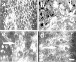
Figure 6
Pathological differences in cellular and nuclear microstructures between normal human skin (a) and skin cancers (b-d) can be noninvasively visualized with confocal microscopy. The skin cancers shown are melanoma (b), basal cell carcinoma (c), and squamous cell carcinoma (d). Normal skin epidermis contains a regular chicken wire-mesh network of circular, oval, or polygonal cells. By comparison, the skin cancers show distinct differences: (b) melanoma cells develop star-shaped projections called dendrites (arrow), (c) basal cell carcinomas show increases in size and migration of basal cells from the superficial epidermis into the underlying dermis (arrow), (d) squamous cell carcinomas show changes in the shape and size of squamous cells in the superficial epidermis (arrow). Scale bar = 25 µm.
exciting applications may include cell-to-cell interactions, microcirculation, drug delivery through the skin, photoaging, and artificial tissue.
Future
Confocal imaging of living tissue is a new imaging modality. Our research effort will increase understanding of the morphology of normal versus abnormal skin. Other tissue types to which we have applied confocal microscopy are oral (lip and tongue) mucosa and bladder. When we compare confocal images to histology slides (i.e., the gold standard), two limitations are obvious: (1) confocal microscopy can probe only the upper 0.5 mm of tissue over fields of view limited to less than 1 mm, whereas histology probes down to depths of 2 to 3 mm over large fields of view, typically 5 mm; and (2) the use of dyes to stain specific cell types enhances tissue contrast, so that critical information necessary for diagnosis can be easily read in histology, whereas confocal microscopy relies on the natural (low) reflectance contrast of tissue without the advantages of stains. At present we are not certain whether diagnosis of skin cancers would be possi-
ble with confocal reflectance microscopy. However, results from our clinical studies strongly suggest that confocal microscopy may potentially be useful for screening skin cancers versus benign (noncancerous) lesions and normal skin, including detection of margins between the lesions and surrounding normal skin. Confocal images may thus provide a useful adjunct to clinical screening and histology by helping a dermatologist make decisions such as whether, where, or when to biopsy a lesion.
Further development of confocal scanning microscopes to make them highly effective for basic research and clinical applications includes several scientific and instrumentation challenges. The main scientific challenge is to understand light-tissue interaction and mechanisms of contrast and to determine techniques to enhance tissue contrast by staining cells types with reflectance microparticles. The instrumentation challenges are to make confocal imaging as similar to histology as possible through vertical sectioning, increasing the depth of imaging, and enlarging the field of view. As with any new imaging modality, we must learn to interpret, analyze, and extract meaningful information from the confocal images. This will involve an extensive correlation of confocal images to conventional (gold standard) histology.
The future will see the development of inexpensive handheld confocal microscopes that will become commonplace in the clinic and linked to each other in a telemedicine network. Although this is being initially applied to easily accessible tissues (skin, oral), the combination of confocal microscopy with other techniques such as laparoscopy should enable imaging of internal organs. Ultimately, optical imaging must be combined with nonoptical imaging modalities to create a noninvasive diagnostic tool kit for the medical profession.
Acknowledgments
Instrumentation development was funded in part by the U. S. Department of Energy and a Whitaker Foundation grant to M. Rajadhyaksha when he was at MGH-Wellman Labs. Clinical and basic research in skin, oral mucosa, and bladder was funded by Lucid, Inc. Credit for research goes to Richard Langley and Melanie Grossman (pigmented skin lesions), Steve Ugent (UVB effects), Salvador Gonzalez (tumor margins, proliferative and inflammatory disorders), Frank Koenig (bladder), and W. Matthew White (oral tissue) at MGH-Wellman Labs.
References
Anderson, R. R., and J. A. Parrish. 1981. The optics of human skin. Journal of Investigative Dermatology 77(1): 13-19.
Bertrand, C., and P. Corcuff. 1994. In vivo spatio-temporal visualization of the human skin by real-time confocal microscopy. Scanning 16(3): 150-154.
Corcuff, P., and J. L. Leveque. 1993. In vivo vision of the human skin with the tandem scanning microscope. Dermatology 186(1):50-54.
Corcuff, P., C. Bertrand, and J. L. Leveque. 1993. Morphometry of human epidermis in vivo by real-time confocal microscopy. Archives of Dermatology Research 285(8):475-481.
Corcuff, P., G. Gonnord, G. E. Pierard, and J. L. Leveque. 1996. In vivo confocal microscopy of human skin: A new design for cosmetology and dermatology. Scanning 18(5):351-355.
Kaufman, S. C., R. W. Beuerman, and D. L. Greer. 1995. Confocal microscopy: A new tool for the study of the nail unit. Journal of the American Academy of Dermatology 32(4):668-670.
Masters, B. R., G. Gonnord, and P. Corcuff. 1997. Three-dimensional microscopic biopsy of in vivo human skin: A new technique based on a flexible confocal microscope. Journal of Microscopy 185(Part 3):329-338.
Minsky, M. November 7, 1957. Microscopy Apparatus. U.S. Patent No. 3013467.
New. K. C., W. M. Petroll, A. Boyde, L. Martin, P. Corcuff, J. L. Leveque, M. A. Lemp, H. D. Cavanagh, and J. V. Jester. 1991. In vivo imaging of human teeth and skin using real-time confocal microscopy. Scanning 13(5):369-372.
Pawley, J. B., ed. 1995. Handbook of Biological Confocal Microscopy, 2nd ed. New York: Plenum Press.
Rajadhyaksha, M., and J. M. Zavislan. 1997. Confocal laser microscope images tissue in vivo. Laser Focus World 33(2):119-127.
Rajadhyaksha, M., and J. M. Zavislan. 1998. Confocal reflectance microscopy of unstained tissue in vivo. Retinoids & Lipid-Soluble Vitamins in Clinical Practice 14(I):26-30.
Rajadhyaksha. M., M. Grossman, D. Esterowitz, R. H. Webb, and R. R. Anderson. 1995. In vivo confocal scanning laser microscopy of human skin: Melanin provides strong contrast. Journal of Investigative Dermatology 104(6):946-952.
Webb, R. H. 1996. Confocal optical microscopy. Reports on Progress in Physics 59(3):427-471.
Webb, R. H., and G. W. Hughes. 1981. Scanning laser ophthalmoscope. IEEE Transactions on Biomedical Engineering 28(7):488-492.
Webb, R. H., G. W. Hughes, and F. C. Delori. 1987. Confocal scanning laser ophthalmoscope. Applied Optics 26(8):1492-1499.
| This page in the original is blank. |


