
C
Reservoir Characterization
Reservoirs range from simple to complex based on their geologic origins. All reservoirs are characterized by some degree of heterogeneity (variability) of properties (porosity, permeability, fluid saturations, etc.) on a variety of scales (Figure C.1). The more complex a reservoir is, the higher its degree of heterogeneity and the more difficult it is to predict the occurrence and producibility of hydrocarbons. Reservoir characterization therefore is necessary in order to understand and predict the occurrence and producibility of hydrocarbons from a reservoir.
Reservoir characterization involves a large component of interpretation. Most producing wells are four to twelve inches in diameter, and most well logs provide constraints on data about rocks six to twelve inches away from the well bore. Therefore, wells provide information about a very small fraction of a reservoir, and hence good interpretation is needed to estimate characteristics of the vast majority of the reservoir located between wells. High-quality reservoir characterization is needed to accurately interpret data from wells and infer the distribution of flow units between wells. Techniques for reservoir characterization include core analysis, wireline log analysis, 3D reflection seismic data, crosswell tomography, vertical seismic profiles (VSPs), transient pressure analysis, tracers, 3D geological modeling, geostatistical modeling of reservoirs, production history matching, fracture analysis, and reservoir fluid analysis (PVT analyses).
Because wells provide information on such a small fraction of the res-
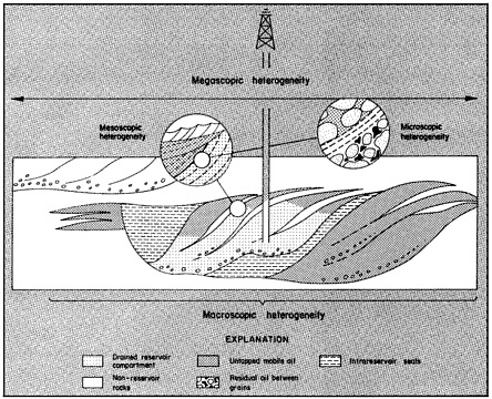
FIGURE C.1 Levels of reservoir heterogeneity. From: Tyler, N., 1988, New Oil from Old Fields. Geotimes vol. 33, no. 7, p. 9. Reprinted by permission of the American Geological Institute.
ervoir, integration of geophysical and engineering data with geological well information is required to give the best interpretation possible. Geophysical techniques can provide information about a large fraction of the reservoir. Conventional 3D seismic data can provide structural data for an entire reservoir, but conventional surface seismic data can only image bodies of rock approximately 100 by 100 by 100 feet. Seismic data cannot, therefore, directly provide data on many of the most important reservoir properties like porosity, permeability, and fluid saturations. And while other geophysical techniques like crosswell tomography can give much finer resolution, they also do not directly provide information on porosity, permeability, and fluid saturations. Fluid flow and pressure data from wells can provide much data on bulk properties of fluid flow within a reservoir. In general, the most accurate and comprehensive estimate of reservoir characteristics results from the integration of geologic, engineering, and geophysical data.
TABLE C.1 GOALS OF RESERVOIR CHARACTERIZATION
|
MAJOR PURPOSE OF RESERVOIR CHARACTERIZATION: LOCATION OF INFILL WELLS |
|||
|
Project No. |
Contractor |
Area |
Purpose |
|
Class 1 |
|||
|
4 |
Texas Bureau of Economic Geology |
Frio Formation |
No field demonstration |
|
6 |
Diversified Operating Corporation |
Sooner Field |
Infill and recompletion locations |
|
9 |
Sierra Energy Company |
Frontier Formation |
Locations of horizontal well to intersect fractures |
|
11 |
University of Kansas |
Savonburg and Stewart Fields |
Locate infill wells and design waterflood |
|
12 |
Oklahoma Geological Survey |
Fluvial-dominated deltaic reservoirs in Oklahoma |
Classification of reservoirs and recovery technologies being used |
|
14 |
Utah Geological Survey |
Bluebell Field |
Locate infill wells and zones to recomplete in existing wells |
|
Class 2 |
|||
|
16 |
Fina Oil and Chemical Co. |
Clearfork Reservoir |
Locate infill wells and redefine waterflood ** |
|
17 |
Laguna Petroleum Co. |
Foster and S. Cowden Fields |
Locate infill wells and redefine waterflood |
|
18 |
Luff Exploration Co. |
Williston Basin |
Locate drilling locations to utilize horizontal drains |
|
19 |
Michigan Tech. University |
Dundee Formation |
Locate horizontal wells |
|
23 |
University of Kansas |
Schaben and Bindley Fields |
Locate infill wells |
|
24 |
Utah Geological Survey |
Paradox Basin |
Locate infill wells and assess viability of waterflood and CO2 flood |
|
**Mid-term project |
|||
|
MAJOR PURPOSE OF RESERVOIR CHARACTERIZATION: IMPROVED DESIGN OF A WATERFLOOD OR ADVANCED FLOODING TECHNIQUE |
|||
|
Project No. |
Operator |
Area |
Purpose |
|
Class 1 |
|||
|
8 |
Lomax Exploration Co. |
Green River Formation |
Waterflood design |
|
11 |
University of Kansas |
Savonburg and Stewart Fields |
Waterflood plus infill |
|
12 |
Oklahoma Geological Survey |
Fluvial-dominated deltaic reservoirs in Oklahoma |
Classification of reservoir and recovery technologies used |
|
13 |
University of Tulsa |
Glen Pool Field |
Waterflood |
|
Class 2 |
|||
|
15 |
Sensor |
Anadarko Basin |
Gel treatment |
|
16 |
Fina Oil and Chemical Co. |
Clear Fork Reservoir |
Locate infill wells and redefine waterflood ** |
|
17 |
Laguna Petroleum Co. |
Foster and S. Cowden Fields |
Locate infill wells and redefine waterflood |
|
20 |
Oxy USA, Inc. |
Welch Field |
Cyclic CO2 flood ** |
|
21 |
Phillips Petroleum Co. |
South Cowden Field |
Horizontal well for CO2 injection ** |
|
22 |
Texaco E&P, Inc. |
Texaco Central Vacuum Unit |
CO2 Huff-n-Puff |
|
24 |
Utah Geological Survey |
Paradox Basin |
Locate infill wells and assess viability of waterflood and CO2 flood |
|
**Mid-term project |
|||
|
LIMITED EMPHASIS ON RESERVOIR CHARACTERIZATION |
|||
|
Project No. |
Contractor |
Area |
Purpose |
|
Class 1 |
|||
|
2 |
Amoco Production Co. |
West Hackberry Field |
Air injection ** |
|
7 |
Hughes Eastern Corp. |
North Blowhorn Creek Field |
Microflora and waterflood ** |
|
10 |
Texaco E&P, Inc. |
Port Neches Field |
CO2 flood with horizontal and vertical wells ** |
|
** Mid-term project |
|||


