
3
Facility Requirements
For the purpose of discussion, the facility1 requirement in this report are divided into the following categories: subsonic and supersonic airplane systems, turbopropulsion systems, hypersonic and transatmospheric systems, and launch and space systems. In general, the committee describes needs in which technology is a driving factor and certain system developments appear likely. Although comments are offered on priorities, the committee believes that a comprehensive study of priorities can be handled only by the structured Air Force Materiel Command (AFMC) planning activity described in Chapter 2.
Several subjects important to the general area of facility requirements are important across the board and are covered in detail in other chapters. For example, the continued improvement that can be provided by advanced computer techniques in operational efficiency, test productivity, and test condition corrections is covered in Chapter 4, and the requirement to broaden the work base of those unique facilities at the Arnold Engineering Development Center (AEDC) that have a continuing usefulness and yet are underutilized is covered in Chapter 5. The requirement to deal with industry and other government agencies to develop key new capabilities in certain areas is dealt with on a case-by-case basis later in this chapter.
The role of the wind tunnel in the design and development of airplanes has changed during the last several decades. The emergence of computational fluid dynamics (CFD) as a development tool during this period has resulted in the wind tunnel and CFD playing complementary roles in configuration development work. Years ago, configuration development
|
1 |
For the sake of simplicity and uniformity throughout the report, the following terms are used to characterize two classes of ground facilities: Research facilities. These facilities are generally highly instrumented and generate high-resolution data for well defined and controlled test conditions. They are used to provide phenomenological insights and to develop and validate computational methods. They are usually smaller in size and shorter in test time than development facilities. In short, they provide the detailed data for understanding the physics and validating and refining computer codes. Development facilities. These facilities are generally used to validate overall design and system durability and performance. They are generally larger in size, emphasize measurements of macroquantities and near-flight conditions, have relatively long test times, cost more to build and operate, and require a very long lead time for acquisition. |
was largely a trial and error process in the wind tunnel, with analytical work providing basic guidance. Now, computational work can provide much more specific guidance to the test work, and significantly improved technology has resulted. In turn, the wind tunnel must play a much more exacting role in the accurate simulation of flight flow fields if the full benefits of available CFD tools are to be realized. This is why one will find continued mention in this report of the desire for higher-test Reynolds numbers (more accurate representation of boundary layer effects) and higher quality test section airflow (e.g., tighter requirements on flow and speed uniformity, turbulence and noise levels, and contamination).
There were those who thought that the spectacular developments in CFD might replace the wind tunnel as a development tool some day. However, Figure 3-1 shows that the opportunities provided by employing both tools result in more tunnel time being used to develop advanced airplane designs, not less. Our increasing demands for advances in complexity and understanding, as well as the requirement to evaluate flight regimes heretofore left unexplored, have contributed to the increased ground test requirements despite the efficiencies provided by CFD tools. Examples of the gains in technology due to this approach are described later in this chapter.
The AEDC wind tunnels have been used for both aerodynamic and propulsion testing. As a result of a 1987 update to flow quality, the 16T wind tunnel's capabilities as an aerodynamic test facility approach the state of the art in many important areas. The wind tunnels provide the quantity of test data needed to support aircraft development by a combination of relatively good productivity and long hours of operation (up to 24 hours per day and seven days per week). The secure environment provided by AEDC for testing on high-security programs led to the choice of 16T over other tunnels in several cases. The large-scale, sophisticated propulsion test and data-gathering capabilities of both 16T and 16S are unique and vitally important to the development of aircraft of strategic significance.
The aircraft aerodynamic and trajectory testing of stores has been an important part of the 16T and aerodynamic wind tunnel 4T work load. Subsequent to the major failure that caused a shutdown of the Navy's 7-foot by 10-foot transonic wind tunnel at the David Taylor Model Basin, the Navy has used AEDC for its stores' aerodynamic and trajectory testing. The current development of independent drive for 4T will allow that facility to operate independently of 16T, thereby increasing the total utilization for both facilities.
AEDC should continue to provide unique aerodynamics and propulsion integration wind tunnel test capabilities for the test and evaluation of Department of Defense transonic and supersonic systems. Also, these wind tunnel test facilities should be made available for the use of commercial endeavors where this supports national policy and objectives.
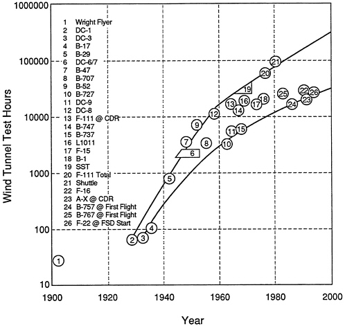
FIGURE 3-1 Wind tunnel testing time as a function of aircraft type and year. Source: Baals and Corless (1981); updated by committee (1992).
SUBSONIC AND SUPERSONIC AIRPLANE DEVELOPMENT
Subsonic and supersonic aircraft configuration testing generally takes place in AEDC wind tunnels 16T (transonic) and 16S (supersonic). Wind tunnel 16T is in great demand, whereas 16S has been lightly loaded, but is unique. A single main drive system supports both the 16T and the 16S wind tunnels, but it lacks the capacity to drive both tunnels at their high-power conditions at the same time. This shared-drive approach has been successful in the past because of the relatively low demand for the supersonic tunnel. However, if demands consistent with the aerodynamic development of a high-speed transport were placed on the 16S tunnel, the 16T tunnel could not simultaneously support the testing load it has encountered in the recent past.
Furthermore, the main motors and drive system may be approaching the limit of their useful lives. The same is true of the plenum evacuation system (PES), which is used on the pumping system for the 16T test section plenum. Replacement of the drive motors is not currently scheduled or budgeted, so there is substantial risk to near-term operation of either 16T
or 16S if one or more of the main drive motors should fail. Replacement motors of this size require approximately 3 years to manufacture and install so the need for replacement must be anticipated in order to minimize the possibility that a test facility is unavailable. Although it would be desirable to have independent devices on 16T and 16S, it may not be possible to accommodate such an arrangement because of space constraints. In any event, it would be prudent to study the replacement options for the main drive system, including cost considerations. These options should be integrated with a monitoring and maintenance plan of the present drive in order that an overall system drive strategy can be established.
Because of the importance of 16T and 16S, the current demands on 16T, and the high cost of replacing the drive system (currently estimated by AEDC at several hundred million dollars for a complete replacement), the committee recommends that AEDC develop a 16T and 16S replacement main drive design, funding plan, and implementation strategy to ensure the continuing availability of these facilities. Also, a means of closely monitoring the integrity of the present drive system should be incorporated to minimize the risk of catastrophic failure.
Transonic Systems Development
As noted, the AEDC 16T is a national asset as a development-oriented, near state-of-the-art propulsion and aerodynamic test facility. Its capability and operation have satisfied the needs of the Air Force for nearly 40 years, an outstanding accomplishment. The AEDC 16T wind tunnel is used for aerodynamic development as well as propulsion testing. In many aerodynamic development tests, the simulation of the propulsion flow field effects is an important capability. As a result of a 1987 flow quality upgrade, 16T's capabilities as an aerodynamic test facility were improved significantly. The 16T provides a large quantity of test data through a combination of relatively high productivity and long hours of operation (up to 24 hours per day, and seven days per week).
The 16T tunnel can generate much useful design data for airplane development work. However, it is no longer the single best capability for developing the design and technology for advanced supercritical wings, which require Reynolds numbers closer to full-scale flight values than can be obtained in 16T. Advanced CFD techniques provide a basis for such designs, which must then be refined and validated in high-Reynolds-number wind tunnel simulation of flow detail.
Figure 3-2 shows how supercritical wing design has benefitted airplane design over the last few decades. Tradeoffs in wing design parameters for several levels of tansonic wing airfoil technology are shown. For a given critical Mach number (cruise Mach number), an aircraft will be most competitive in other ways (e.g., fuel volume, empty weight, and lift-to-drag ratio [L/D]) if it can achieve that critical Mach number at the minimum wing sweep angle and the thickest wing design. In Figure 3-2, one can see that technology advances have provided an increase in wing critical Mach number of about 0.03 (for a given wing sweep and thickness ratio) for each 10-year period from 1960 to 1980. Throughout this period, full-scale flight aerodynamics could be simulated well enough in conventional low-Reynolds-number wind tunnels to achieve these results. In the last 10 years or so, the improvements that were made required higher-Reynolds-
number tunnels (such as the 11-foot transonic tunnel at NASA Ames Research Center) to refine and validate the advanced wing designs. As wing design technology continues to advance, it appears evident that the wind tunnel boundary layer simulation must be improved, which will require an even higher test Reynolds number.
Another requirement for a high-flow-quality, high-Reynolds-number test capability comes from the need to develop and test cruise laminar flow control (LFC) applications. Here again, a near-full-scale-flight Reynolds number is required because proper boundary- layer aerodynamic representation is important. The fact that these advanced aerodynamic systems have not yet found their way into actual production designs is partly due to the lack of appropriate development facilities. Other reasons involve projected costs of such applications, complexity, and tolerance to the real world environment (such as bugs and rain). However, it is interesting to note that each LFC research program in recent years has resulted in performance equal to or better than expected.
The requirement for higher-Reynolds-number transonic testing does not mean that 16T is obsolete. On the contrary, that facility may be the most efficient and productive way to accomplish the major part of transonic testing development work. Therefore, AEDC is encouraged to continue to improve the flow quality, decrease the noise level, and improve the
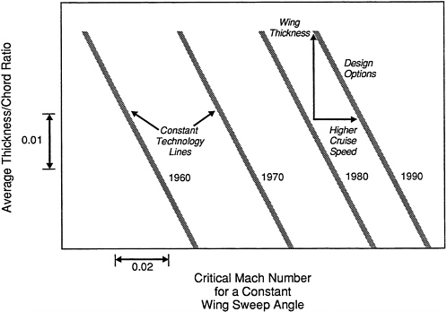
FIGURE 3-2 Technology advances in airplane wing design. Source: Internal, unpublished data. The Boeing Company.
operational productivity of 16T to enhance its capability in performing work where the Reynolds number capability of 16T is adequate. If a new high-Reynolds-number facility were to be built, and only the Air Force testing that required high Reynolds numbers were placed there, it is unlikely that there would be enough demand to keep the facility at a reasonably cost-effective work load. Therefore, AEDC should look at options other than building a new facility solely for Air Force use. The Ames Research Center 11-foot transonic tunnel is a research facility that also supports industry. Its Reynolds number capability is somewhat short of that desired, but it has been the only facility available for most high-Reynolds-number applications work. The Langley Research Center National Transonic Facility (NTF) is a cryogenic nitrogen gas facility with full-scale flight Reynolds number capability, but was not designed for day-to-day development production testing.
Industry, like the Air Force, needs a high-Reynolds-number transonic facility for similar transonic airplane developments. Existing test facilities are inadequate and industry is also considering options for developing this capability.
The committee recommends that AEDC, with the close cooperation and support of NASA and industry, develop alternative strategies for providing the ability to ground test cost-effectively at transonic speeds at near-flight Reynolds number. The alternative strategies should include estimates of costs, benefits, timing, and anticipated utilizalion. In formulating a recommendation for consideration by the AFMC, the LRPT should consider the alternatives presented by AEDC, other facilities that may be coming on line, and alternative development tools (other than ground testing) for obtaining the required higher-Reynolds-number data for Air Force development programs.
Low-Speed Configuration Development Testing
When AEDC was established, there were adequate numbers of high quality, low-speed tunnels available. Thus, AEDC did not construct low-speed aerodynamic test facilities. Such testing supports the design and development of high-lift systems for transonic and supersonic aircraft, controllability tests for the development of post-stall fighter agility, and landing configuration tests for transatmospheric systems. In many of the above development tests, it is very important to simulate accurately the effect of the propulsion system flow on the aerodynamic flow field. Similar to the situation in transonic testing, earlier high-lift technology did not require testing at near-full-scale Reynolds numbers. However, the technology has advanced to the point where it makes a difference in critical areas, and the role of AEDC should be reconsidered.
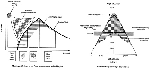
One important technology in the design of fighter aircraft involves the tailoring of post-stall maneuvering capability. This is in addition to the very important pre-stall flight regime in which complex and controlled maneuvers have always been important. The total envelope has been expanded significantly, with major emphasis on increased agility and supermaneuverability. The upper part of Figure 3-3 shows a traditional maneuver envelope bounded by a maximum lift coefficient at low speeds and by a structural limit at higher speeds. The regions labeled “Post-Stall Pitch Pointing” and “Herbst Maneuver” represent expansions of the traditional maneuver
envelope where future fighter aircraft will need to be precisely controllable. The traditional maneuver envelope is being expanded in other dimensions, also. The lower portion of Figure 3-3 shows the loaded roll capability of today's fighter aircraft. The region labeled “Lateral Agility Expansion” represents increases in the desired roll controllability and roll authority up to the angle of attack corresponding to maximum lift coefficient. The region labeled “Post-Stall Pitch-Pointing Expansion ” represents unprecedented increases in aircraft controllability at angles of attack greater than those corresponding to maximum lift coefficient. Controlling these maneuvers demands exact information about the forces acting on the aircraft during the maneuver. Lift on these maneuvering aircraft is maintained at extreme angles of attack by creating strong vortices that interact with the wing. The vortices follow the curvature of the wing, producing low pressure on a region of the lifting surface. Roll control is maintained by inducing the vortex over each wing to follow the wing curvature for a controllable distance. Varying the point at which the vortex detaches from the wing or forebody produces a different lift on each wing and thus roll. The driving phenomenon is the interaction of the inviscid and viscous flow fields. In such inviscid-viscous interactions, proper Reynolds number simulation frequently is very important.
Although computational techniques are being developed to help design and predict the aerodynamic characteristics under supermaneuverability flight conditions, CFD will be used primarily to augment and help focus the wind tunnel test program. It is desired that certain key fighter characteristics and capabilities be refined and validated at near-flight Reynolds number test conditions.
All conventional airplanes, subsonic and supersonic, have important performance requirements for takeoff and landing. Because the effectiveness of the high-lift devices significantly influences this capability, it can have a major effect on other elements of the design such as wing area requirements. Airplane L/D and maximum lift coefficient (for a given flap setting) are two important parameters in optimizing high-lift-system geometry for both takeoff and landing performance. Takeoff performance is controlled by a balance of two conditions--a requirement to meet minimum climbout conditions (high L/D desired) and the requirement to meet field length requirements (high-maximum-lift coefficient desired). The landing field length is influenced by the airplane maximum-lift coefficient in the landing configuration. Landing L/D is also important, due to the influence of approach power requirements on approach noise levels.
Developing the high-lift-system geometry at near-full-scale Reynolds number improves both the maximum-lift performance and the maximum-L/D performance in the high-lift configuration. Once again, it is the ability of advanced CFD analysis along with the refinement and validation of the high-Reynolds-number wind tunnel tests that allows this technology to advance.
Much high-Reynolds-number development work in this country has been run in the Ames Research Center's 12-foot, low-speed pressure tunnel. However, the pressure shell of that facility reached the end of its useful life due to structural fatigue a few years ago, and the facility is currently under reconstruction. During the period in which the Ames 12-foot tunnel has been out of operation, U.S. industry has used European high-Reynolds-number, low-speed test facilities in order to remain technically competitive. It must also be noted that although the Ames 12-foot and several European tunnels can approach or match flight Reynolds numbers for fighter-sized aircraft, none can match the Reynolds numbers of larger transport aircraft.
It is difficult to judge what, if any, new low-speed high-Reynolds-number facilities should be developed in the United States. The Ames facility (in a new, improved, and more highly productive version) will be available in 1994, and it is not clear what the total needs of the country (industry plus government) will be.
The committee recommends that AEDC, with the close cooperation and support of NASA and industry, develop alternative strategies for providing the ability to ground test cost-effectively at low speed at near-flight Reynolds number. The alternative strategies should include estimates of costs, benefits, timing, and anticipated utilization. In formulating a recommendation for consideration by the AFMC, the LRPT should consider the alternatives presented by AEDC, other facilities that may be coming on line, and alternative development tools (other than ground testing) for obtaining the required higher-Reynolds-number data for Air Force development programs.
Supersonic Cruise Vehicles--Military and Commercial
The 16S wind tunnel is a unique national asset that finds infrequent but essential use in support of military programs. No other supersonic wind tunnels provide the same high-productivity, high-quality, and large-scale test environment available in the AEDC 16S tunnel. The 16S and 16T tunnels also are unique among U.S. facilities in that they offer these qualities for both propulsion and aerodynamic testing.
It is likely that the supersonic cruise technology being pursued by NASA and industry, in the judgment of the committee, will result in a commercially viable supersonic transport. It is just as likely that supersonic cruise applications will be developed by the USAF. In the opinion of the committee, indications point to the interest of Europe and Japan in challenging the United States in this technology. Wind tunnel 16S is the logical major development tool in the United States for such applications. To be attractive to U.S. industry, the charge levels must be competitive in accord with the recommendations in Chapter 5.
In preparing for the future increased utilization of 16S, a modernization plan should be developed, including the following considerations:
-
wind tunnel drive replacement;
-
emphasis on capability in the Mach 1.5 to Mach 3.2 range;
-
efficient test productivity by advanced computer management (Chapter 6);
-
improved flow quality, including flow uniformity, low noise level, low turbulence level;
-
accommodations for simulation of engine airflows and their effects on airplane flow field; and
-
accommodations for supersonic laminar flow testing.
The committee recommends that AEDC develop an upgrade and funding plan for wind tunnel 16S in anticipation of increased demand for the development of supersonic cruise vehicles.
TURBOPROPULSION SYSTEMS
To meet the needs of a new generation of aircraft systems during the next 10 to 30 years, air-breathing engine test requirements for AEDC will be a function of engine size, type, and configuration.
The Integrated High Performance Turbine Engine Technology (IHPTET) program is the U.S. initiative and rallying point for achieving a higher thrust-to-weight ratio and improving engine performance. Improving the core engine (gas generator) performance is the key to developing improved air-breathing engines for both military and commercial applications.
Figure 3-4 shows the relationship between specific core gas power and turbine rotor inlet temperature, which illustrates that improved performance is indeed possible (Koff, 1991). The core power is normalized by the mass flow so both large and small engines can be represented. During the past 50 years, the core power has steadily increased with turbine temperature by a
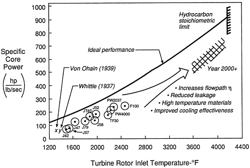
FIGURE 3-4 Improving core performance of turbopropulsion systems.
factor of five over the early jet engines of Whittle and von Ohain. Demonstrator engines have operated successfully at eight times the power of these early engines. The ideal Brayton cycle performance is shown representing 100 percent component efficiencies and no cooling air. The theoretical performance is truncated at the fuel stoichiometric limit (fuel/air ratio = 0.068) at which all oxygen and fuel are consumed. The core power theoretical limit is almost 20 times higher than the early turbojets and 4 times higher than current engines in production. Given that actual engine power will be lower than the ideal, a concentrated technology effort can be expected to achieve an increase in core power of 2.5 over current production engines within the next 20 years.
The trend to higher core engine power through technology advances is the key to the configuration design of fighters, airlift (transports), and strategic and commercial aircraft because they all use the core engine to develop the gas power for the propulsion system. The categories of air-breathing engines can be covered in three basic flight regimes: subsonic, supersonic, and hypersonic.
Subsonic (Commercial)
Three basic types of commercial engines are being developed to reach the “final frontier” in subsonic propulsion as illustrated by the cross-hatched region in Figure 3-5 :
-
high bypass ratio (5:9) direct drive turbofans (size to 90,000-pound thrust);
-
very high bypass ratio (10:16) geared drive turbofans with reversing pitch blades for thrust reverse, using slimline nacelles to minimize interference drag with the wing/pylon installation (size to 120,000-pound thrust); and
-
ultrahigh bypass ratio (40:60) unducted propulsors using reversing pitch blades for thrust reverse (size dependent on application).
Supersonic (Commercial)
Work is under way to overcome technical barriers (noise, emissions, and economics) in the NASA High Speed Research program. This program will develop the advanced technologies required for a high-speed civil transport, currently projected to be in the Mach 2.5 range. AEDC is already well postured to meet the propulsion test requirements for the high-speed program and will play a key role.
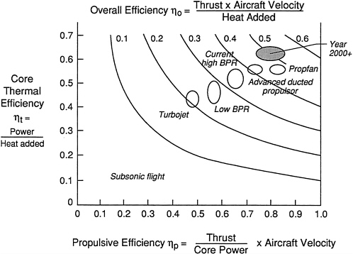
FIGURE 3-5 Trends in overall efficiency of turbopropulsion systems indicating a target goal in 2000+ for high efficiency. Source: Koff (1991).
Military (Subsonic-Supersonic-Hypersonic)
Military engine technology is concentrating on
-
low observables (radar and infrared);
-
vectoring nozzles (pitch and yaw);
-
direct lift coupled with lift fans;
-
higher thrust-to-weight ratio;
-
supersonic cruise using the higher-energy core engines to drive higher fan pressure ratios; and
-
producing derivatives by using the technology base.
Airlift transports will most probably adapt advanced commercial engines to provide increased range and payload.
The major portion of hypersonic technology funding is currently focused on the Mach 0 to 25 National Aero-Space Plane program (see next section). These technologies will be useful in other hypersonic programs. Studies are continuing to define Mach 3 to 5 engines for hypersonic applications. However, with or without government support, hypersonic applications are likely to be in the Twenty-First Century.
For the future, alternative propulsion fuel sources other than petroleum-derived fuels will undergo intensive investigation. These initiatives will require special facilities, and AEDC needs to stay current. The nuclear propulsion option, as an example, could become a practical reality sometime during the next 30 to 50 years.
Figure 3-6 shows that the current AEDC Aero-Propulsion Systems Test Facility (ASTF) is adequate for altitude testing of the newest generation of high-bypass engines, such as the PW4084 and GE90. However, a 40 percent increase in flow capacity is required to handle the next generation of ultra-high-bypass, gear-driven propulsor engines with certification in the late 1990s. Testing of these larger engines is already being planned. The Pratt & Whitney demonstrator engine will be sea-level tested at the NASA Ames Research Center in 1993-1994. These engines also require testing in the reverse pitch mode and at high angles of attack.
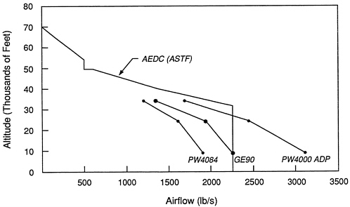
FIGURE 3-6 ASTF exhauster capability of large engine stands. Source: Pratt & Whitney (June 1991).
The committee recommends that the LRPT (with strong support from AEDC) develop options for meeting the projected large propulsor airflow and diameter requirements of the next decade. These options should include, for example, increasing the current facility capabilities, testing the propulsor separately, testing engines with shortened (or clipped) versions of the propulsor, and using flight testbeds.
HYPERSONIC CRUISE AND TRANSATMOSPHERIC SYSTEMS
During the 1950s and 1960s, numerous hypersonic flow facilities were constructed in the United States and put into operation in support of research on hypersonic aircraft and re-entry vehicles. These facilities included a range of shock tunnels, expansion tubes, and vitiated and nonvitiated intermittent blowdown facilities, primarily at government sites and universities. When national priorities shifted away from research on hypersonic aircraft in the 1970s, resources for ongoing and future programs sank to very low levels, resulting in termination of nearly all of the government-funded work in government laboratories, industry, and universities.
This environment caused many of the hypersonic research facilities to be dismantled or shut down and research on large, high-Mach-number facilities to be sharply stopped. This essentially eliminated initiation of plans for construction of follow-on facilities that would have been required for full-scale design, development, test, and evaluation of hypersonic vehicles, particularly air-breathing vehicles. As a consequence, the hypersonic facilities that currently allow relatively large-scale components and systems to be tested are few in number and operate primarily in the Mach number range below 8. Higher Mach number hypersonic facilities currently in operation are typically small in size, with short test times, and in virtually all cases provide only partial flow simulation. They are research and development facilities suited primarily for research testing.
The National Aero-Space Plane (NASP) program, which was initiated in 1986, has provided added visibility to the limitations of the existing flow facilities and testing capabilities, particularly for development testing across the entire hypersonic range. It also highlights the absence of adequate research facilities and instrumentation at the higher hypersonic Mach numbers. The NASP X-30 flight research vehicle will be designed to explore single-stage-to-orbit technology, using an air-breathing propulsion system as the primary means of propulsion from horizontal takeoff to near orbital speeds. The air-breathing propulsion system for a hypersonic vehicle is a highly integrated part of the airframe: the forward portion of the airframe provides the external compression system for the inlet, and the aft portion of the vehicle serves as the engine exhaust nozzle. This requires testing the propulsion and airframe systems as fully integrated systems, using experimental models and techniques that simulate the close coupling of the internal and external flow fields. This is a unique requirement compared to prior aircraft designs, which were more amenable to successful testing as separate components.
Up to about Mach 8, the conventional ground testing approach can be utilized for the X-30 type of design and scale. However, many of the existing hypersonic facilities were designed primarily for research and lack some of the characteristics--such as large size and rapid model change capability--that are so valuable for development testing. Major propulsion system and structural components that are tested on a relatively large scale in existing facilities have flows
that are contaminated (e.g., active species, water, combustion gases, noise, turbulence). Computational fluid dynamic techniques have limited ability to specifically evaluate the effects of all of these contaminated flows on aerodynamics and propulsion performance at this time.
In contrast, for Mach numbers greater than about 8, the NASP program is testing for the development of the X-30 vehicle by using limited experimental data from existing partial-simulation, short-duration facilities to validate, as much as possible, the results of less mature computational methods. These numerical methods will then be applied to the broader set of flight conditions in the X-30 operating envelope to provide design performance projections for the entire X-30 operating envelope. Data from the early flights of the X-30 experimental vehicle will check the validity of the lower-Mach-number results, where both experimental data and computational analyses are available. Later flights, through methodical expansion of the operational envelope, will be designed to gather additional data in the higher-Mach-number range, not available from ground facilities. Although this is a higher-risk approach than traditionally used in the design, development, and testing of prototype or operational aircraft, it is the only possible procedure given the lack of adequate ground test facilities, and is consistent with previous “X-aircraft ” programs.
The information learned from flight tests of the X-30 may greatly enhance our understanding of the hypersonic flight environment and the performance of the integrated components and systems that comprise that particular vehicle design. However, the possibility exists that any one of a wide variety of operational hypersonic vehicles may be required for the future, ranging potentially from cruise aircraft to orbital vehicles that have vastly different design and performance requirements. To prepare for this possibility, plans for a structured, lower risk process for development, test, and evaluation of major vehicle components and systems are needed. Lowering the risk to a level comparable to that currently required for a commitment to full-scale development of a supersonic fighter aircraft, such as the F-15, will require new hypersonic ground development facilities for testing large-scale components and systems with good flow simulation throughout the hypersonic flow regime.
Hypersonic development facilities--particularly for aerodynamics, propulsion, and control, but also, to some extent, for structures and materials--require a close simulation of the full conditions of flight. The test section size must be adequate for the testing of full geometries or significant components, which in some cases may be close to full size (possibly requiring on the order of a 5-foot test section diameter or more). Adequate test time (from a fraction of a second to several seconds or more) is needed to permit the testing of key aerodynamic and propulsion phenomena over a period of time during which conditions can be varied, the model geometry can be changed, active cooling can be evaluated, and so forth. For some simulations, particularly when no air-breathing propulsion is involved, millisecond test times may be adequate. However, there are no present facilities that meet the combined criteria of flow quality, time, and full simulation, even at Mach numbers as low as 5.
With the limitations of ground test facilities and the complexity of phenomena at hypersonic speeds (such as aerothermodynamics, chemical reactions, and high heat transfer), it seems likely that full simulation of all conditions throughout the hypersonic flight regime may not be possible. A combination of carefully designed partial-simulation ground test facilities, computational fluid dynamics including chemical reactions, and some flight tests will be needed to provide the design, development, and certification for hypersonic vehicles.
It is possible, using proven technology, to satisfy the test requirements below about Mach 10. Clean flow of high quality and possibly quiet conditions (for boundary-layer development) are feasible in a range up to Mach 8 or 9. Above Mach 10, maintaining temperatures and pressures required for the full simulation of flight, while meeting the requirements of clean air and long-duration operation, has not been demonstrated thus far. When chemistry becomes an important part of the test (e.g., combustion, real gas effects, surface catalysis), the effects of flow contamination seriously degrade the ability of the facility to do development testing. There are some research facilities that begin to approach these conditions, but usually for very short times and on a small scale. There are few possibilities for future solutions of the development facility problems. With only partial simulation, a complete hypersonic development test capability probably requires several facilities, flight tests, a strong computational development program, and a high level of risk for the development of advanced vehicles.
Building a hypersonic development facility is reasonable only if the facility will provide a unique capability in a range of key importance to hypersonic flight. Such a possibility exists in the Mach number range around 8 where several important hypersonic phenomena are well established. Real gas effects on aerodynamics are present but not strong, but combustion at elevated temperatures is important. For air-breathing propulsion, supersonic combustion is probably required, and the shift from subsonic to supersonic combustion must be investigated. Boundary layers at high Mach numbers, with such conditions as high heat transfer and active cooling, pose problems quite different from those at lower speeds. Storage heaters have demonstrated the capability to generate the temperatures and stagnation pressures equivalent to flight in this range. With available technologies, the storage heater can provide clean flow for a facility that can be made large enough and run for long enough times for development work. A description of a possible two-phase program including such a facility is detailed in the following paragraphs. However, for the higher-Mach-number range, there is, at the moment, no facility concept that has demonstrated the capability of meeting the full development requirements, although some possibilities seem within reach for research facilities. In the following paragraphs, some detailed steps are outlined that might constitute a “roadmap” for hypersonic development facilities for the next 20 years at AEDC.
The Phase One program might include the development of a new facility using existing technology from the DoD and NASA facilities and an intensive program aimed at higher-Mach-number concepts. A key first step for AEDC would be to develop a unique testing facility in the Mach 8 range with the characteristics of clean air and quiet operation. Using existing facilities or elements at AEDC and applying some of the experience of the Aerodynamic and Propulsion Test Unit (APTU) could provide the least expensive initial phase of a long-term program. The APTU heater is fully qualified to generate the stagnation pressures and temperatures for flight Mach numbers of approximately 8, with a test section size on the order of 5-feet in diameter, with run times of 1 to 120 seconds. By using advanced ceramic brick for the heater, filters, and available vacuum capacity, with some planning for a possible modification in the future for quiet operation, such a facility would provide a unique capability.
This Phase One facility is needed to provide early and specialized data for both aerodynamic and propulsion testing. In addition, Phase One could provide a direct way to calibrate the testing being done with combustion, arc-heated, and short-duration facilities; evaluate CFD predictions; and be a focus for hypersonic aerodynamics and propulsion in the
United States. It would also provide the capability for a focused research program to define the parameters and characteristics for a Phase Two facility for Mach numbers above 10. The committee believes that planning for the Phase One program should be undertaken immediately. This program cannot be fully carried out at AEDC, but AEDC should be strongly involved in the advanced facility research with NASA and capitalize on the advances made by the Europeans and the Russians.
The major problem with present development (and research) facilities above Mach 10 is that the test section flow does not simulate flight. Active particles, generated by the high-temperature stagnation requirements, are frozen into the flow by the nozzle expansion. Other contaminants caused by the heating process (e.g., by arcs and combustion) are also present in the test section flow. Without a fully-simulated real flow, it is critically important to evaluate the effects of contaminants on test results. It may be possible to obtain good results for some tests, but a major effort is needed to provide the tools with which to make evaluations. Measurements of specific constituents of the flow, computations that take the full chemistry into account, and calibration checks (either flight tests or comparison with clean flows) are required. The development facility research effort should consider the following items:
-
Development of arc-heated facilities. This has been underway for many years, but appears still to be limited because of contamination from the electrodes and the nonequilibrium condition of the airflow. Furthermore, the relatively low operating pressure of present arc-heated facilities is a serious performance limitation. The arc seems to be a key element in hypersonic testing as an enthalpy generator for structures and materials testing. There will always be questions regarding flow quality and contamination and their effects on combustion and heat transfer. If there is a clean air facility (such as that described earlier), a direct comparison might possibly demonstrate that the arc facility could be an even more useful tool. The continuing development currently appears to be limited to Mach numbers of approximately 10 to 12 except where contamination is not important.
-
Examination of scaling the shock-expansion tube to the run times and sizes required for development facilities. The expansion tube seems to have excellent possibilities for generating conditions for very high Mach numbers if only for short times. A detailed examination is needed.
-
Research on nozzle throat technology for full flight conditions above Mach 10. The problems here are probably involved with active cooling and questions of boundary layer control, which may be key to quiet tunnel development. NASA's experiences in the development of quiet wind tunnels at Mach numbers of 6 and 8 should be closely monitored since new research efforts in this area could have a major effect on development facilities of the future.
-
Evaluation of liquid-air arc concept. This concept has had limited study. The ability to evaluate this new technology for a possible development facility cannot take place unless significant facility research is supported.
-
Examination of magnetohydrodynamic (MHD) acceleration. The old concept of MHD acceleration has been revived, along with some new concepts. These should be examined in detail and brought to the stage where the value of this technology as a possible driver for a large development facility can be evaluated.
-
Alternative to air-breathing configurations. Although a strong emphasis has been placed on the future testing of air-breathing configurations, there is a sizable future requirement for other possible configurations (such as gliders and rocket-powered vehicles), Pulse facilities, widely considered for research, must be examined for scaling that might permit their application to development testing of complex configurations.
-
Exploration in bigger flight range. The free flight range has provided excellent results for some problems in the past. The possibilities of a big range, which could have a major impact on future capability, are critically dependent on driver technology. Electromagnetic, ram-accelerator, and other types of drivers have possibilities that need to be explored. Demonstrated technology would provide a base for future commitments.
With the results of the Phase One program outlined above, there is the potential for a Phase Two program, using an enlarged storage heater, available high-pressure air, and the unique vacuum capacity of ASTF to provide a large development facility based on the APTU experience. By using experience with the Phase One system and inputs from NASA's ongoing research regarding the possibility of quiet operation, the possible value of such a facility could be carefully evaluated. With the results of the research on new concepts and the advances in present techniques from Phase One, Phase Two could provide the base with framework for the long-term development facility construction.
There should be no major development facility commitment made above the Mach number of 10 until facility research and a prototype can demonstrate capabilities satisfying the requirements for development testing. The questions about partial simulation have not been resolved. However, if Phase One were accomplished, the direct comparison at a Mach number of 8 will give some indication, although not complete, of the ability to use several partial-simulation facilities for major vehicle development.
The committee recommends that, within the LRPT structured planning activity, a roadmap be created for the development of ground test facilities for transatmospheric and hypersonic cruise systems. A two-phase program is recommended. Phase One would include development of a high-quality, state-of-the-art, Mach 8 facility, accompanied by parallel research programs aimed at critical hypersonic test facility issues. Based on the results of Phase One, Phase Two could entail the design and construction of the selected major development facility resulting from the Phase One program. Because of the uniqueness and responsibility of operation of the hypersonic development ground test facilities and the possible use of extensive present air and vacuum capability, it is recommended that Phase One be a primary responsibility of AEDC.
LAUNCH AND SPACE SYSTEMS
The testing of components of launch vehicles, including those of ballistic missiles and space vehicles, is a very important capability of AEDC. In the past, such testing consisted of evaluating the aerodynamics of launch vehicles, including such vehicles as the Titan IV; testing liquid propellant and solid propellant rocket engines under realistic conditions in a vacuum environment; characterizing rocket plumes; evaluating the performance of reentry vehicles; testing payload fairing separation dynamics; and testing spacecraft in a simulated space environment. Recently, AEDC has developed new capabilities in evaluating focal plane arrays and has used those capabilities to support a variety of programs, particularly several programs of the Strategic Defense Initiative.
AEDC has developed several unique national resources relevant and necessary for the continued development of ballistic missiles, as well as space and launch vehicle technology. Particularly noteworthy are the AEDC capabilities to test rocket motors of considerable size in a vacuum environment, to perform appropriate diagnostics of burning rocket motors, and to characterize the properties of the rocket plumes. These capabilities have proven essential for the development of rocket engines for space and Intercontinental Ballistic Missile applications and have assisted in analyzing anomalies that occur during operations. The developing capability to evaluate infrared focal planes has the potential of providing an objective government resource for the characterization and evaluation of sensor systems in a facility whose technical characteristics are state of the art and well understood.
In an environment of shrinking resources and a shrinking business base (the rate of new system technology starts in the ballistic missile and space system areas is very low), the challenge in the immediate future is to preserve and protect and, where appropriate, to modernize unique capabilities at AEDC so that technology development in ballistic missiles and space and launch systems can continue and be supported by the capability to adequately and realistically test the system components. Wherever feasible, AEDC should search for synergistic investments so that several sets of requirements for testing can be met with a single facility. This will also ensure that facilities are available to assist in anomaly analysis when the inevitable failures in space or launch systems occur during operations.
In the judgment of the committee, and given the historical strengths of AEDC in flow-related facilities and expertise, priority should be assigned to ensure the continued effectiveness of the capability to test rocket engines in a simulated space environment with appropriate diagnostic capabilities. These capabilities, coupled with the continued ability to test re-entry vehicle materials and structures, are essential for testing the components of our current space boosters and ICBM force, as well as providing the capabilities that may be needed to support future ICBM and space launch-related development. The committee supports the AEDC plan to reconfigure Rocket Development Test Cell J-4 to test liquid propellant rockets. This capability will put AEDC in a posture to participate in the developmental testing of the next generation of upper-stage liquid rocket engines such as might be utilized by the joint NASA/DoD National Launch System. The committee also supports AEDC work on Test Cell J-6, which will give AEDC the capability of testing 500,000-pound-thrust engines to altitudes of 100,000 feet in a manner consistent with safety concerns.
The committee recommends that AEDC continue to give high priority to providing state-of-the-art capability as a national resource for liquid and solid propellant rocket testing.
Planning to Meet Future Needs
There is a perception that laboratories and development centers such as AEDC are not involved as early in the planning phases of the weapon systems development process as they should be. Various alternative approaches have been tried to improve this situation: none has been totally successful. The one course that seems the most effective is to enhance communications between the system program offices and AEDC through formal briefings, establishment of liaison offices, and temporary assignment of AEDC personnel to the program offices of interest. In this way a closer coupling of the user and AEDC will develop, to the mutual benefit of both parties. Planning, in coordination with DoD laboratories, is also necessary to ensure that the capability to test next-generation propulsion systems, such as electric or plasma engines, will exist when needed. This coordination should be sufficient so that AEDC is also at the state of the art in applying new testing and diagnostic technology developed in the laboratories to its own mission.
The future of AEDC will be well served by having in place a process that continually develops options for new test facilities and capabilities. Although only a fraction of these options may be realized, the very process of option development may sharpen technical insights and develop the advocacy needed to keep AEDC at the cutting edge of development testing technology and facilities.
Space System Testing
Another issue involves the use by program offices of contractor-owned test facilities rather than the use of central Air Force facilities located at AEDC for space system testing. Every major space system contractor has, in the past 20 years, developed space test facilities. These facilities are an essential part of the production line for space systems and are an element of the competitive strategy of each contractor. The environmental testing of each spacecraft during the production process is a key ingredient in ensuring the quality of the product. Program offices believe that it is more efficient and more cost effective to utilize facilities at a contractor site for performance evaluation rather than to transport each spacecraft, its ground support equipment, and the testing team to another location for periods that are uncertain but may extend up to substantial parts of a year for each spacecraft tested. Instead, they prefer to utilize AEDC for development testing only when AEDC facilities provide unique capabilities.
The question sometimes arises as to whether or not there is sufficient independent evaluation of the performance of space system components and systems. This is related somewhat to the previous question in the sense that contractor-owned facilities are often used for performance evaluation. Of course, evaluating performance at contractor facilities requires a good understanding by the Air Force of those test facilities and of the advantages and disadvantages of operating there in contrast to comparable government-owned facilities. Typically, the testing of each space and launch vehicle program at the system and subsystem
levels is extensively reviewed by independent readiness teams formed from personnel with space systems expertise but not associated with the program. These teams critically review the testing as it is proceeding and also review the test results to ensure that performance requirements are met.
The committee believes that, generally, the present mode of operation of the Air Force in developing, testing, and evaluating space systems results in cost benefits to the government. At the same time, the committee believes that sufficient oversight of the evaluation process exists to ensure an understanding of competitive systems. The previously mentioned system-planning organization at the Air Force Materiel Command headquarters, which is responsible for the identification of tools needed for the development of new systems, would be an invaluable forum where AEDC could learn of new space system requirements and participate in the test planning in a timely way.
The committee recommends that AEDC continue to provide unique capabilities as a national resource for simulated space environmental testing.


