= exp [−k1(ln 2)] .
(15)
A plot of ηmax as a function of k2 is shown in Fig. 12. For any given value of k2, the values for the optimum counting time and the corresponding efficiency can be determined from Fig. 11 and Fig. 12.
As can be seen from Fig. 12, the value of maximum efficiency decreases with increasing k2. As an example, let us consider a nuclide with a half-life of 2 s; if k2 increases from 1 to 2 to 4 (i.e., from 2 s to 4 s to 8 s), the maximum efficiency decreases from 0.375 to 0.272 to 0.185. As the sample changing time increases to 8 s, the efficiency decreases to a fairly low value of 0.185. For a nuclide with a half-life of 1 s, the low value of 0.185 is reached even when the sample changing time is 4 s. The time required for chemical separation will essentially be the deciding factor as to whether the autobatch technique will be acceptable for studying nuclides with half-lives on the order of a second or less. On the other hand, a continuous chemical separation procedure may not be available for a given element of interest; hence, one must use an autobatch procedure even if the efficiency is low.
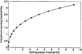
Figure 11. Optimum counting time as a function of precipitation time.
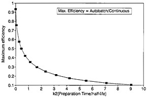
Figure 12. Maximum efficiency as a function of preparation time.
4. Autobatch Techniques
It is impossible to study short-lived nuclides within the required time of a few seconds by carrying out chemical separations manually using conventional techniques. This led to the
automation of part or all of the steps in the procedures. Often, classical techniques had to be modified or adapted so that the procedure could be handled conveniently by the automated system. For example, rapid exchange of ions in solution with preformed precipitate was used instead of precipitation from aqueous solution. Solvent extraction was performed by dispersing the solvent on an inert material and contacting the aqueous solution with this material.
A semi-automated system was used by Greendale and Love in their work on arsenic, tin, and antimony. They designed a system for rapidly transferring irradiated solution from the rabbit to a chemistry system in about 2 s [Gre63c]. The cap of the irradiation container had a Teflon and gum-rubber diaphragm. The irradiated rabbit impinged on two hypodermic needles; the solution was drawn through one of the needles by application of vacuum, while the second needle was used to let air or rinsing solution enter the rabbit. The solution was transferred to a vessel containing carrier solutions by manipulation of stopcocks. Again, by operating a few stopcocks and using nitrogen gas, they were able to generate hydrides of arsenic, tin, and antimony. Separated arsenic, tin, and antimony samples were available in about 10 s [Gre63a, Gre63b].
The first completely automated system for rapid radiochemical separation was reported by Schüssler and coworkers [Sch69]. The solution to be irradiated was sealed in polystyrene capsules. After irradiation using a pneumatic tube facility, the capsule containing the solution was transferred directly to the chemical separation apparatus. Impact on the wall of the apparatus broke the capsule, and the irradiated solution was sucked through a layer of preformed silver chloride. Fission halogens exchanged with chloride. Next, a washing solution was sucked through the silver halide. After the washing, a pneumatic system transported the separated fraction to a counter. The entire operation was performed with the use of syringes, valves, and stopcocks that were operated automatically by an electronic programmer. The entire sequence of operation was initiated by a signal received from photodiodes placed in the reactor, and was triggered by the Cerenkov radiation accompanying the neutron burst of the TRIGA reactor. Counting of the sample started 3 s after the end of irradiation. Schüssler and Herrmann used the system to study short-lived fission halogens [Sch72]. Similar systems used for the study of short-lived silver and technetium nuclides are described in Sec. 4.1 and Sec. 4.2.
Autobatch procedures based on solvent extraction using high-speed centrifugal contactors have been utilized to study short-lived palladium and silver nuclides [Mei80, Mei81]. The system is described in Sec. 4.3.
A microprocessor-based system was developed for the study of short-lived arsenic and antimony nuclides [Mey80]. The entire cycle of operations —from the loading of rabbits to counting of the sample—was controlled by the microprocessor. Details of the system are presented in Sec. 4.4.
Separations of individual lanthanides and actinides require complex ion-exchange chromatography; autobatch procedures based on such separations have been developed. Short-lived lanthanide nuclides were studied by the Idaho group using a combination of extraction and ion-exchange chromatography [Bak80, Bak81, Bak82]. A description of the technique is given in Sec. 4.5. Schädel and coworkers have reported autobatch procedures based on chromatography for the separation of transplutonium elements [Sch88b, Sch89]. Their microcomputer-controlled automatic rapid chemistry apparatus (ARCA) is described briefly in Sec. 4.6.
A large number of autobatch separation procedures are available. Table 10 gives a list of elements for which autobatch procedures are available in the literature. The table also lists the technique used in the separation, the time required for the separation, and the procedure number.
Several examples of autobatch chemical systems are described in the following sections. The systems are selected to illustrate the use of different types of batch techniques (solvent extraction, exchange, etc.).
Table 10. Autobatch procedures.
|
Element |
Technique |
Timea |
Procedure # |
|
Actinides |
Gas chromatography |
Few min |
An-1 |
|
Antimony |
Volatilization |
1.6 s |
Sb-1,5,11 |
|
Arsenic |
Volatilization |
1.9 s |
As-1,2,7 |
|
Dysprosium |
Extraction, ion exchange |
<9 min |
Dy-1 |
|
Gadolinium |
Extraction, ion exchange |
3.2 min |
Gd-1 |
|
Germanium |
Volatilization |
~5 s |
Ge-1,2 |
|
Hafnium |
Ion exchange |
10–20 s |
Hf-3 |
|
Lanthanides |
Extraction, ion exchange |
<3 min |
Ln-1 |
|
Lanthanides |
Gas chromatography |
Few min |
Ln-3 |
|
Lawrencium |
Cation exchange (HPLC) |
160 s |
Lr-4 |
|
Lawrencium (from Md) |
Extraction (HPLC) |
1–2 min |
Lr-5 |
|
Mendelevium |
Cation exchange (HPLC) |
200 s |
Md-2 |
|
Mendelevium (from Lr) |
Extraction (HPLC) |
1-2 min |
Md-3 |
|
Molybdenum |
Extraction |
5 s |
Mo-1 |
|
Neptunium |
Extraction, ion exchange |
2.7 min |
Np-2 |
|
Niobium |
Adsorption |
2.2 s |
Nb-1,3,8 |
|
Palladium |
Extraction |
<1 min |
Pd-1,2 |
|
Promethium |
Extraction, ion exchange |
<3 min |
Pm-1 |
|
Protactinium |
Extraction |
23 min |
Pa-3 |
|
Ruthenium |
Extraction |
8.3 s |
Ru-3 |
|
Samarium |
Extraction, ion exchange |
~11 min |
Sm-1 |
|
Selenium |
Volatilization, extraction |
5 s |
Se-1 |
|
Silver |
Exchange |
4.1 s |
Ag-2 |
|
Tantalum |
Extraction |
10–20 s |
Ta-3 |
|
Technetium |
Extraction |
2.5 s |
Tc-6 |
|
Technetium |
Volatilization |
1 s |
Tc-4 |
|
Tellurium |
Volatilization |
5.0 s |
Te-1 |
|
Terbium |
Extraction, ion exchange |
<3 min |
Tb-1 |
|
Tungsten |
Ion exchange |
10–20 s |
W-2 |
|
Yttrium |
Ion exchange |
10 s |
Y-2 |
|
Z = 104 |
Extraction |
2–3 min |
104-1 |
|
Zirconium |
Extraction |
2.2 s |
Zr-1,3 |
|
a Time reported is for the fastest procedure. |
|||
4.1 Autobatch Techniques for the Separation of Silver Isotopes
Brüchle and Herrmann [Brü82] studied short-lived silver isotopes formed in fission using isotopic exchange of Ag+ with preformed silver chloride precipitate. They used both a manual and an autobatch technique in their studies. In both cases, the fission-product solution was treated with an oxidizing solution containing K2Cr2O7, H2SO4, and Ce(IV); this treatment oxidized fission halogens. The solution was then filtered through freshly preformed silver chloride that exchanged with Ag+ present in the fission-product solution. The precipitate was then washed with an oxidizing wash solution of H2SO4 (8N) and K2Cr2O7. The silver chloride was then dissolved in ammonia, reprecipitated, and filtered. The filtered sample was used for counting. This manual procedure was performed in a glass apparatus by manipulating a number of stopcocks. The entire procedure took about 42 s from the end of irradiation, and the time could be reduced to about 28 s if two people performed the operations.
The apparatus used for autobatch separation of silver is shown in Fig. 13. Recoiling fission products were caught in an ammonium nitrate catcher and pneumatically transported to the apparatus within 0.6 s after the end of irradiation. The entire chemistry operation was performed by the opening or closing of magnetic valves connected to a pressure or vacuum system. The stopcocks (made of Teflon) were moved pneumatically. Most of the apparatus was made of polymethylmethacrylate. The sequence of opening and closing valves was controlled by an electronic programmer. The NH4NO3 catcher material containing the fission products was dissolved in a mixture of 2N H2SO4 – K2Cr2O7 solution (by operation of stopcock 1, Fig. 13), and the solution was filtered through preformed AgCl. The AgCl with 8N H2SO4 – K2Cr2O7 solution (operation of stopcock 2) and then with water (stopcock 3). The AgCl was then dissolved in 6N NH4OH (stopcock 4) and reprecipitated by mixing the solution with 6N HCl (stopcock 5) and filtered (stopcock 6). The timing of each operation is shown in Fig. 13. The final sample was pneumatically transferred to the counting position. Counting was started at 4.1 s after the end of irradiation. More than a hundred separations were performed using the apparatus to accumulate gamma-ray spectra with good statistics.
4.2 Technetium by Solvent Extraction
Use of the solvent-extraction technique in the autobatch process is well illustrated by the procedure developed by Trautmann and coworkers [Tra72] for their study of short-lived technetium isotopes. The chemical steps consisted of removing the halogens from the fission-product solution by exchange with preformed silver chloride, oxidizing technetium to pertechnetate by ammonium persulfate in the presence of Ag+, and extraction of technetium with tetraphenylarsonium chloride in chloroform on Chromosorb. The technetium was then eluted from the Chromosorb layer.
Figure 14 shows the apparatus used for the technetium chemistry. The top of the apparatus was made of polycarbonate, and the other parts of it were made of polymethylmethacrylate; the stopcock plugs were made of Teflon. The entire operation was carried out by an electronic programmer, as in the case of the silver chemistry described in Sec. 4.1.
Figure 14 shows the operational details of the apparatus, including the timing of operation of each valve and stopcock. The capsule containing the irradiated 235U or 239Pu solution, transferred pneumatically from the reactor, was smashed by impact on the walls of the vessel within 0.2 s after the end of irradiation. By application of vacuum at position 1, the fission-product solution was sucked through two layers of silver chloride. The fission-product halogens were removed by exchange with the silver chloride. The silver chloride layers were washed with 2 mL of 0.1N HNO3 containing tartaric acid by opening stopcock 1 from 0.7 to 0.8 s. The fission-product solution and the washings were collected in 0.2 mL of 0.2M (NH4)2S2O8 containing AgNO3. The
persulfate oxidizes technetium to pertechnetate. The application of vacuum in position 1 was stopped at 1.2 s.
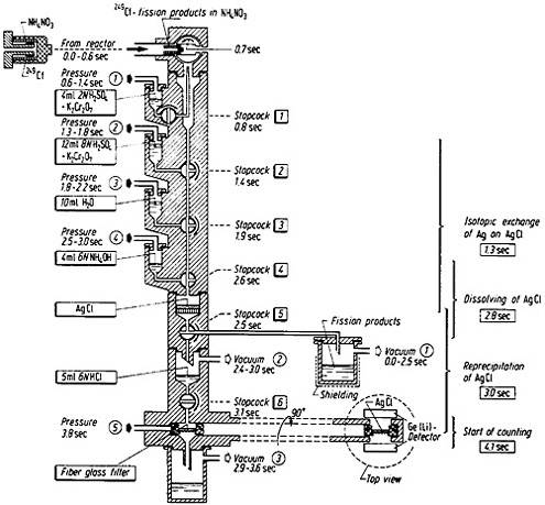
Figure 13. Automatic apparatus for the separation of silver from fission products. [Brü82; reprinted with permission from Radiochim. Acta]
The fission-product solution was filtered through a layer of Chromosorb containing tetraphenylarsonium chloride (Ph4AsCl). The Chromosorb layer was prepared by mixing 2 mL of 0.025M Ph4AsCl in chloroform with 1 g of Chromosorb 102 (100/120 mesh). The Ph4AsCl solution also contained 1% pyridine. Filtration was accomplished by applying vacuum at position 2 and opening stopcock 2. The Chromosorb layer was washed with 15 mL of 0.1N HNO3 containing tartaric acid; the wash solution was transferred by opening stopcock 3 and applying pressure at position 2. The filtrate and the washings were collected in a shielded container. The technetium was then eluted with 10 mL of 2N HNO3 containing NH4ReO4; elution was initiated by opening stopcock 4, applying vacuum at position 3, and also applying pressure at position 3. The eluate was collected in 3 mL of 0.05M Ph4AsCl in water. Under these conditions, rhenium precipitated as Ph 4AsReO4; technetium coprecipitated with rhenium. The precipitate was filtered by opening stopcock 6 and applying vacuum at position 4. The precipitate was then washed with 2 mL of 0.1N HNO3; this was initiated by the opening of stopcock 7. The precipitate was transferred to the counting station by applying pressure at position 5. The counting could be started 7.5 s after the end of irradiation.
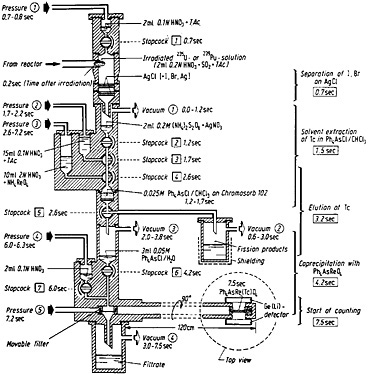
Figure 14. Apparatus and time schedule for the rapid separation of technetium from fission products by solvent extraction of pertechnetate ions. At the right-hand side, the mean time of each separation step is indicated. [Tra72; reprinted with permission from Radiochim. Acta]
4.3 Palladium by Solvent Extraction
The palladium separation procedure reported by Meikrantz and coworkers [Mei80, Mei81] is a good example of the adaptation of conventional solvent extraction technique for fast separation with the use of miniature centrifugal contactors. Figure 15 shows a schematic of the palladium chemical separation system they used. A microcomputer controlled the entire separation system. Fission products from a 252Cf source were transported by a helium jet containing NaCl aerosol and were deposited on a Mylar tape. A collection time of 2 min was used; at the end of collection, the tape was moved to the centrifugal contactors for solvent extraction studies. Siczek and coworkers [Sic80] have described the use of a miniature dissolution chamber where the deposit was dissolved in warm (70°C) 1.5 mL of 8M HNO3 – 0.1M HCl containing several carriers. The pH of the fission product solution was adjusted to 1 by the addition of 1M NH4OH, and then the palladium was complexed with dimethylglyoxime (DMG). Dichloromethylene was added to the mixture with rapid stirring, and the entire mixture was then pumped to the first centrifugal contactor. The Pd(DMG)2 extract in CH2Cl2 was transferred to a second contactor, where it was scrubbed with 1M HNO3. The extract was then transferred to the third contactor, where the palladium was stripped with 3M NH4OH. Palladium was reduced, along with silver, using a zinc column. The time at each step of the separation is shown in Fig. 15. Counting could be started 135 s from the end of collection of fission products. Using this system, Siczek and coworkers prepared 20 samples sequentially for their study.
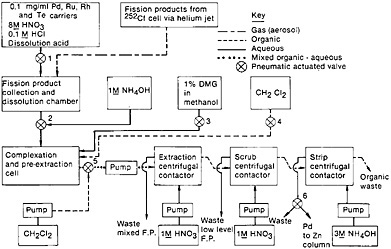
Figure 15. Schematic of autobatch separation of palladium from fission products. [Mei81; reproduced with permission from Radiochim. Acta]
This system was also used to isolate pure palladium (separated from silver daughters) by adjusting the pH of the NH4OH strip from the third centrifugal contactor to 1. The precipitated Pd(DMG)2 was filtered on a glass-wool column. The separation was achieved in 150 s. Figure 16 shows a schematic for this part of the separation. Isolation of silver daughter activities from short-lived palladium isotopes was also achieved using this system. The NH4OH strip from the third centrifugal contactor was acidified with 8M HNO3 and passed through a column of preformed silver chloride (replacing the glass wool column used in the palladium procedure with an AgCl column). The column retained silver activities by isotopic exchange; since Pd(DMG)2 precipitates slowly from high-acid solution, palladium remained in solution during this stage. Silver was isolated in 165 s from the end of fission-product collection; 45 samples were prepared sequentially for this study.
The system described above shows that many of the procedures developed for batch processes using solvent-extraction technique (described in Sec. 2.4) can be adopted for autobatch processes with the use of a miniature centrifugal contactor for phase separation. Another such system for solvent extraction uses high-speed, motor-driven centrifuges. The system known as the AKUFVE system is described in Sec. 6.1 under “ High-Speed Centrifuge for Phase Separation.”
4.4 Arsenic and Antimony by Volatile-Hydride Production
The Fast Chemistry Group at LLNL used a highly automated system [Mey80, Lie81, Lie82] for the study of short-lived arsenic and antimony isotopes. A microprocessor controlled the entire process, starting from loading and sending rabbits through a pneumatic tube for irradiation, to starting the counting and simultaneously cleaning the chemistry system. The chemistry involved production of hydrides of arsenic, selenium, antimony, and tellurium by the reaction of sodium borohydride. Selective decomposition of hydrides allowed study of arsenic and antimony isotopes.
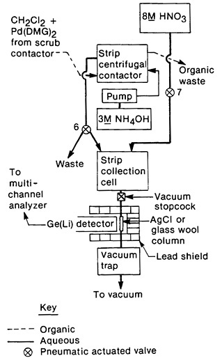
Figure 16. Schematic of the palladium/silver collection system. [Mei81; reprinted with permission from Radiochim. Acta]
Figure 17 shows a schematic of the operation cycle used at LLNL. A microprocessor loaded a rabbit containing 1 mg of 235U in solution, and sent it to the reactor core for irradiation. After a preset irradiation time, the rabbit was transferred through another pneumatic system to a chemistry laboratory fume hood. The rabbit was caught and moved to a second position, where the fission-product solution was extracted and transferred to a reaction chamber containing carrier solutions. The solution was purged with nitrogen gas for 600 ms to remove fission krypton and xenon. Addition of sodium borohydride solution at this point generated hydrides of arsenic, selenium, antimony, and tellurium; for the separation of arsenic, the hydrides passed through a trap containing CaSO4 and NaOH, which removed selenium, tellurium, and antimony. The AsH 3 flowing through was decomposed and caught on glass wool containing HCl and Br2.
The time sequence of the chemical separation is shown in Fig. 18. The entire operation took 1.9 s. The microprocessor started the counting and simultaneously initiated the cleaning of the reaction chamber and the loading of the next rabbit. Figure 17 shows the time required for the these operations. The total cycle time was less than 30 s. In a typical 12-h day, more than 1000 isolation measurement cycles could be performed. In their study of 5.3-s 84As, Henry and coworkers [Hen81] performed over 10,000 cycles of the arsenic chemistry using the system described above. The runs performed during the course of 10 days accumulated 25 million coincidence events. The fact that such chemical separations could be performed using highly automated systems indicates the reliability and usefulness of autobatch techniques for ultrafast chemistry.
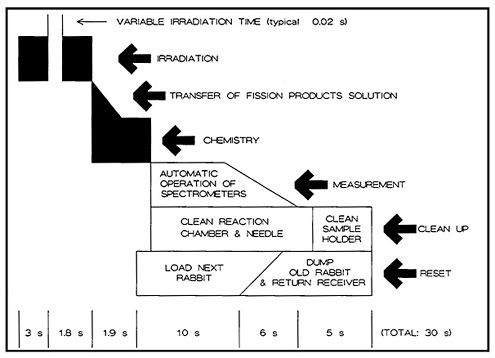
Figure 17. Time sequence of the autobatch antimony-arsenic cycle. [Reproduced with permission from R. A. Meyer]
4.5 Autobatch Separation of Individual Lanthanide Fission Products
Separation of individual lanthanides has been the most difficult problem faced by chemists. As pointed out in the earlier sections, ion-exchange resins made faster individual separation of lanthanides possible. Using microcolumns, Choppin and coworkers [Cho56b] achieved separation of lanthanides within 2 h using Dowex-50 cation-exchange resin and α-hydroxyisobutyric acid as eluent, and good separation of adjacent lanthanides took about 16 min [Ren64].
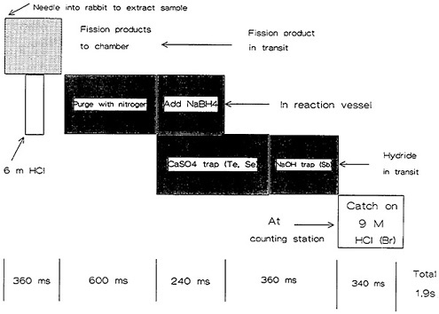
Figure 18. Time sequence of the arsenic-antimony chemical separation system. [Reproduced with permission from R. A. Meyer]
High-pressure liquid chromatography was utilized to separate lanthanides by Schädel and coworkers [Sch77a] and by Elchuk and Cassidy [Elc79]. The nuclear chemistry group at Idaho National Engineering Laboratory developed an automatic chemistry system using high-pressure liquid chromatography for the separation of lanthanides [Bak80, Bak81, Bak82]. The system is described in the following paragraphs.
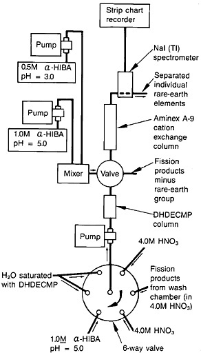
Spontaneous fission of 252Cf served as the source of fission products. The recoiling fission fragments were thermalized in a helium-gas jet and carried by the NaCl aerosol. The fission products were deposited on a Mylar tape. A schematic of the fission-product collection chamber, transport mechanism, and dissolution chamber is shown in Fig. 19. After collection for a preset time, the microprocessor moved the tape to the next station. The tape was covered with a second tape during transport to a wash chamber, where the fission products were dissolved with 1 mL of hot (70°C) 4.0M HNO3.
The lanthanides were separated from the fission-product solution using extraction chromatography, and individual lanthanides were separated using cation-exchange chromatography; the system operated under high pressure. Figure 20 shows a schematic of the element separation chemistry system for lanthanide. The outlet of the dissolution vessel was connected to a six-way rotary valve. The extraction-chromatography column, 5.0 cm long and with a 3.2-mm i.d.,
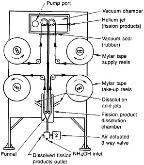
Figure 19. Schematic of the autobatch lanthanide separation system. [Bak82; reprinted with permission from J. Radioanal. Chem.]
contained Vydac C8 resin saturated with dihexyldiethylcarbamoyl-methylphosphonate (DHDECMP). The fission-product solution was pumped to the DHDECMP column, and the rotary valve was connected to a supply of 4.0M HNO3. The lanthanides were adsorbed onto the column while other fission products were washed to the waste in about 30 s. By switching the valve to the next position, α-hydroxyisobutyric acid at pH 5.0 was passed through the column. The lanthanides were washed out of the column in about 15 s. At the end of this cycle, the rotary valve was switched to the last position to pump H2O saturated with DHDECMP, which was used to regenerate the column.
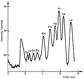
The lanthanide fraction was collected in a 1-mL sample loop and injected onto an Aminex A-9 resin column (15.0 cm long by 3.2-mm i.d.). A gradient elution technique with α-hydroxyisobutyric acid as eluent was used. The elution was started with 0.65M acid at a pH of 3.6 and gradually changed to 0.95M acid at a pH of 4.8. The column was operated at 95°C. A typical elution curve is shown in Fig. 21.
The entire system was controlled by microprocessor. The Idaho group has used the system for the study of a number of short-lived lanthanide fission products. They carried out a number of separations for each study. Decay properties of short-lived promethium [Gre82], samarium [Bak80], gadolinium [Geh82a], terbium [Gre83], and dysprosium [Geh82b] have been reported.