
2
Anticipated Technical Performance of the ATD/NTOT
The proposed ATD/NTOT is not a typical scientific mission in which technical specifications, derived from top-level science requirements, must be met during development, construction, and deployment. Rather, it is a mission designed to demonstrate newly available technologies that may be used in future DOD missions and that have obvious applications to scientific missions. As such, its performance must be characterized differently since it will be assembled, as much as possible, from existing components and designs rather than according to the specific requirements for a particular task. In this respect, the ATD/NTOT has more in common with the recent Clementine lunar orbiter than, say, the Hubble Space Telescope.
This chapter discusses the baseline concept for the ATD/NTOT as described by representatives of Itek and Lockheed. The technical evaluation of the mission is based on the task group’s assessment of those aspects of the ATD/NTOT whose performance can be approximately predicted on the basis of these briefings. In other words, the task group describes the performance levels that the ATD/NTOT is most likely to achieve. The actual performance will be defined more clearly as launch approaches, although still not perfectly, given the nature of any technology demonstration. For this reason, the task group considers it essential that the astronomical community view the ATD/NTOT mission primarily as a demonstration and test of astronomically important technology, with significant scientific results being a hoped for, but not necessarily guaranteed, bonus. Recommended deviations from the baseline, where they significantly enhance astronomical performance, are identified in the course of this analysis.
BASIC DESIGN FEATURES
The telescope is the most fundamental element in determining the value of the ATD/NTOT mission for astronomy. Some of its key features have not been used previously in any astronomical telescopes in space. These features include:
-
A 4-meter-aperture, thin-facesheet, primary mirror equipped with some 260 position actuators for on-orbit refiguring;
-
Afocal optics with an image-stabilization mirror located at an image of the entrance pupil to adjust the pointing anywhere within a ± 5.7-arc-minute region without moving the spacecraft;
-
Graphite polycyanate (graphite epoxy) structures for the entire telescope assembly;
-
Use of an on-board inertial reference to maintain pointing stability over a bandwidth from 1 to 300 Hz;
-
The ability to track stars, as faint as 19th magnitude, through the full aperture of the telescope to maintain pointing stability against disturbances at frequencies of less than 10 Hz; and
-
A design optimized for agility and rapid slewing from one point on the sky to another.
The layout of the proposed telescope and details of its optics are shown in Figure 2.1 and Figure 2.2, respectively. Its basic design is that of an afocal, three-mirror anastigmat. The use of three mirrors permits good imaging performance over a relatively large field of view. The 4-meter-diameter, f/1.25 (a design with a focal ratio of f/1.7 is also possible) parabolic primary mirror is 17 mm thick and is equipped with some 260 actuators to control its shape. The convex secondary and concave tertiary mirrors are both hyperboloids. The optical parameters of all three mirrors are given in Table 2.1.
The telescope relays an image of the entrance pupil from the primary mirror to a flat image-stabilization or fast steering mirror (FSM) with a demagnification of 40 (i.e., with an exit pupil diameter of 10 cm). (A demagnification of 20 is another possibility.) The FSM, located at the relayed pupil, is used to stabilize the image at frequencies up to 300 Hz over an area of sky 0.2 degrees across.
The FSM is followed by a dichroic beam splitter that divides the light into infrared and visible branches at a wavelength near 1 micron. These separate beams are subsequently directed to a number of different focal planes by additional beam dividers and reimaging optics. The visible branch contains a wavefront sensor used to assess the shape of the primary mirror and generate correcting signals for the primary ’s figure control actuators. The assumed parameters of the completed telescope are summarized in Boxes 2.1 and 2.2These numbers are used in subsequent sections that address the ATD/NTOT ’s optical performance.
EXPECTED POINT-SPREAD FUNCTION
Knowledge of the observatory-level point-spread function (PSF) and encircled energy is useful for defining the kinds of science and the spectral region to which an optical system such as the ATD/NTOT is best applied. In practice, of course, this determination is a complex systems engineering issue requiring many kinds of input and much analysis. However, the PSF can be estimated by considering two factors known about the ATD/NTOT: its line-of-sight stability and its figure error.
Line-of-Sight Stability
The telescope’s line of sight is maintained at frequencies greater than 1 Hz by illuminating a quad cell with a gyroscopically stabilized light beam from a so-called Inertial Pseudo-Stellar Reference Unit (IPSRU). The resulting error signal is sampled at 300 Hz and used to drive the FSM so that it keeps the telescope’s image fixed relative to the focal plane. Although the IPSRU’s gyros drift at a rate of the order of 5 milliarc sec (mas) per second, they are corrected at frequencies of less than 10 Hz by determining the centroid of the image of a guide star viewed with the fine-guidance CCDs. The error-budget allotment for image stability is quoted as 4.5 mas per axis; thus, the two-dimensional image stability is 6.5 mas. The task group convolved this figure with a Gaussian to broaden expected point-spread functions.
Figure Error
For this discussion, the ATD/NTOT telescope is assumed to consist of five mirrors. The first three are the primary, secondary, and tertiary mirrors of the afocal telescope assembly. The fourth is the FSM at the reimaged telescope pupil, and the fifth is a hypothetical mirror required to bring light to a focus. Bringing the telescope to focus over a reasonable field of view actually requires at least two optics, but assuming only one makes only a small difference in predicted performance. Since astronomical telescopes generally feed a focused image to their instruments, the inclusion of the FSM and a focusing optic allows a direct comparison with performance at the focal plane of other telescopes.
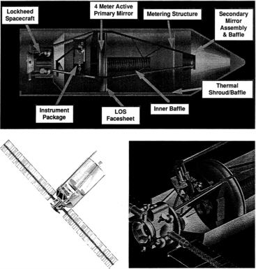
FIGURE 2.1 Key features of the ATD/NTOT. Components not used before in any astronomical telescope in space include a lightweight 4-meter mirror with active optics, an afocal design using a fast steering mirror and an on-board inertial reference for image stabilization, and a graphite polycyanate structure for the entire telescope assembly. Upper panel: This view of the ATD/NTOT packed inside the shroud of a Proton booster shows the layout of the principal components, including Lockheed ’s spacecraft bus—the F-SAT—and the thin, 4-meter primary mirror derived from Itek’s Large Optical Segment (LOS) project. Lower left panel: A view of the ATD/NTOT in orbit with its solar panels extended. Lower right panel: A detail of the ATD/NTOT showing (left) the F-SAT bus with its solar panels extended, (center) the instrument package, and (right) the rear face of the primary mirror and its adaptive-optics system. (Courtesy of Lockheed.)
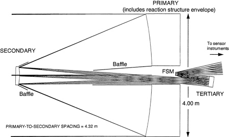
FIGURE 2.2 The ATD/NTOT’s secondary and tertiary mirrors relay an image of the entrance pupil from the primary mirror to a fast steering mirror (FSM). The FSM is followed by a dichroic beam splitter that divides the light into separate infrared and visible beams at a wavelength near 1 micron. These separate beams are subsequently directed to a number of different focal planes by additional beam dividers and reimaging optics. The visible branch contains a wavefront sensor (not shown) used to assess the shape of the primary mirror and to generate correcting signals for the primary mirror’s figure control actuators. (Courtesy of Lockheed.)
TABLE 2.1 Specifications of the ATD/NTOT’s Primary, Secondary, and Tertiary Mirrors Based on Information Received from Lockheed and Itek
|
Parameter |
Primary |
Secondary |
Tertiary |
|
Aspheric type |
Paraboloid (CC = −1.000) |
Hyperboloid (CC= −1.690) |
Hyperboloid (CC = −1.009) |
|
Parent |
|||
|
Size |
400.0 cm |
58.9 cm |
38.6 cm |
|
F-Ratio |
f/1.25 |
f/1.33 |
f/2.47 |
|
Aspheric |
528.1 µm |
101.3 µm |
|
|
Aspheric slope |
1.8 µm/mm |
2.8 µm/mm |
|
|
Section |
|||
|
Size |
33.8 cm |
||
|
Offset |
2.527 cm |
||
|
F-Ratio |
f/2.82 |
||
|
Aspheric |
8.15 µm |
||
|
Aspheric slope |
0.3 µm/mm |
||
|
Footprint |
400.0 cm |
54.8 cm |
10.0 cm |
|
Test type |
Parabola test with compensator |
Hindle |
Parabola test with compensator |
The primary mirror’s actuators correct figure errors below the Nyquist frequency of about 10 cycles per aperture. The resulting, post-correction figure error will then be the residual error below the Nyquist frequency and uncorrected errors at higher frequencies.
There are two principal sources for the residual wavefront error in the so-called baseline telescope design for the ATD/NTOT. First, on the basis of previous programs, Itek estimates that the primary mirror will have a surface accuracy of roughly 35 nm rms and thus will contribute 70 nm rms (2 × 35) to the wavefront error. Second, the four additional optics will contribute an additional 37 nm to the telescope’s wavefront error (based independently on test data supplied by Itek and by estimating errors individually for each optic based on size, speed, and conic). The combination of these two errors is 80 nm rms. The disproportionate contribution to this total due to the roughness of the primary mirror suggests a possible enhancement. Since obtaining improved surface accuracy at frequencies of 10 to 20 cycles per aperture is likely to be relatively inexpensive, it is possible that the final figure quality could be improved dramatically and cost-effectively by seeking a better figure on the primary mirror. Since scattered light scales with the square of the figure error, even modest improvements in figure can result in significant performance gains. These gains and their consequences are discussed in Box 2.3, “Enhanced Telescope Design.”
Point-Spread Functions
To model the PSFs the task group generated a synthetic power spectrum of the errors in the surface figure to represent the figure error of the optics as filtered through the actuator system. A power-law spectrum was assumed and then filtered within 10 cycles per aperture. The integrated residual figure was normalized to that of the particular telescope design being evaluated (i.e., either the baseline or the enhanced design discussed in Box 2.3 ). The filtered and unfiltered power spectra are shown in Figure 2.3. Using this synthetic power spectrum of the primary, the assumed power spectrum for the other optical elements, and an assumed broadening due to jitter, PSFs were calculated at various wavelengths.
The PSFs and encircled energies of the baseline design in the visible and near-infrared regions are given in Figure 2.4. At a wavelength of 1 micron, the Strehl ratio is ~0.75. At 0.6 micron, the encircled energy in the central peak is 45% (this compares favorably with the prerefurbished HST’s Strehl ratio of 0.15). The full width at half maximum (FWHM) at optical wavelengths is better than that for any current or planned facility. The
|
Box 2.2 ATD/NTOT Weight Summary (in kilograms) Based on Information Received from Lockheed and Itek
|
|
Box 2.3 Enhanced Telescope Design As has been established, the roughness of the primary mirror dominates the system error in the baseline telescope design. Thus, improving it leads to a directly proportional improvement in the total system. This, in turn, allows much improved astronomical imaging and also allows a much better evaluation of the various components of the technology and how they contribute to the quality of the images. Many astronomical investigations push the limit of spatial resolution and require the maximum contrast in a scene. The extent to which this is needed for DOD’s demonstration of technology is outside the task group’s scope of expertise, although it seems likely that if the DOD missions involve reconnaissance rather than just target acquisition and tracking, then maximizing the contrast in the images may be important. It may also be important even for acquisition and tracking on faint targets. Itek estimates that improving the surface of the primary mirror by a factor of two—to less than 20 nm rms compared to less than 40 nm rms as now specified—would cost approximately $100,000. Assuming that this enhancement is made, ITEK’s experience suggests that a requirement of 20 nm rms would lead to a primary mirror with an actual surface error of about 17 nm rms. To assess this possibility, the task group analyzed a departure from the baseline in which the primary mirror and telescope-level residual wavefront errors are, respectively, 34 and 50 nm rms. It does not make sense to consider enhancing the primary’s figure much (say, by more than another factor of two) beyond this level since, at this point, the system’s figure error is being driven by the remaining optics in the telescope and focal plane. The point-spread functions (PSFs) and encircled energies for the enhanced design at the visible and near-infrared wavelengths are given in Figure 2.5. The value of the enhanced figure requirements is evident from a comparison with Figure 2.4. The performance relative to the diffraction limit improves at longer wavelengths as shown in the two figures, although the full width at half maximum (FWHM) naturally increases in absolute units at longer wavelengths. At infrared wavelengths, the system is approaching the diffraction limit in the baseline (Strehl > 0.8), and so the gain with the improved primary is not large. At optical wavelengths, however, the image quality is dominated by errors in the primary mirror in the baseline, so that improving that single specification makes a large difference in both the Strehl ratio and the diameter of the circle with 50% encircled energy. (In the task group’s crude modeling, the FWHM of the central peak is already very good and does not change significantly with the improvement in figure). Even at 0.8 micron, an improved primary mirror ensures that the various sources of error are approximately comparable so that the various limitations on the telescope’s performance can be reliably assessed at optical wavelengths where the performance is much more critical. At the shortest wavelengths, significant power from a point source is redistributed far from the central core so that the circle with 50% encircled energy is increasing as the wavelength decreases, even though the FWHM of the central peak is decreasing. The enhanced design pushes the wavelength of the minimum circle down to the vicinity of 0.6 micron. Making this enhancement would lead to a dramatic improvement in the ATD/NTOT’s astronomical performance at optical wavelengths. There should be an improvement by a factor of two in contrast between a point source and the background at a wavelength of 0.75 micron, leading to a corresponding improvement in the limiting magnitude of the system, since the dominant noise source at these wavelengths is the zodiacal light. The improvement in resolution is equally important for studying the spatial structure of sources at this range of angular sizes and could make the ATD/NTOT dramatically better in spatial resolution than the Hubble Space Telescope, even with the planned Advanced Camera. The ability to evaluate all aspects of the technology for their applicability to astronomy is also dramatically improved by the improved surface accuracy. There are many other sources of error that cause the PSF to deteriorate, including the stability of the field distortion, the stability of the tracking, and so on. When the contribution of these sources is small compared to the errors of the primary mirror surface, it becomes much more difficult to evaluate the degree to which these sources are satisfactory. The task group concludes, therefore, that this enhancement is very desirable and in subsequent discussions refers to the so-called enhanced telescope design frequently, comparing it with the baseline design where appropriate. |
relatively poor figure of the primary mirror, however, leads to a diameter for 50% encircled energy that is no better than that of the HST. The performance relative to the diffraction limit improves at longer wavelengths, although the FWHM naturally increases in absolute units at longer wavelengths. At infrared wavelengths (λ > 1 micron), the system is approaching the diffraction limit (Strehl ratio > 0.8).
Not included in these calculations is any effect due to surface micro-roughness or to the 5% of the light striking the primary mirror that is diffracted wide of the image core by the “spider” supporting the secondary mirror. Itek has considerable experience in building mirrors with small micro-roughness, and published figures indicate a limit of 1 nm for the micro-roughness; the task group has not considered this issue in detail. The effect of the secondary supports is about five times larger for the ATD/NTOT than for telescopes with a more traditional truss design. Thus images with more greatly pronounced spider flares can be expected (Figure 2.6). The quantitative effects of the spiders can be approximated by multiplying the PSFs and encircled energies by 0.95. Print-through of the actuators is included implicitly in the peak at 10 cycles of the task group’s filtered surface-power spectrum (see Figure 2.3), although circular symmetry is assumed and the print-through will enhance the effects at certain azimuths of the PSF.
The results of the task group’s analysis are summarized in Table 2.2, which compares the baseline and enhanced (see Box 2.3) specifications for the primary mirror, taking into account the 5% loss due to diffraction on
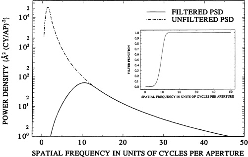
FIGURE 2.3 The synthetic power spectrum of surface figure errors generated by the task group to represent the figure error of the optics both before and after filtering through the actuator system. The filtered spectrum was found by assuming a power-law spectrum that was filtered to within 10 cycles per aperture using the inset filter function.
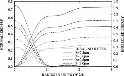
FIGURE 2.4 The task group’s calculated point-spread functions (PSFs) and encircled energy curves are shown for the baseline design of the ATD/NTOT with a total wavefront error of 80 nm (i.e., for a primary mirror having a wavefront error of 70 nm and assuming a pointing jitter of 6 milliarc sec). All PSFs are normalized such that their integral over all space is unity when focal-plane coordinates are expressed in units of λ/D (where D is the telescope’s aperture). By scaling out the wavelength in this manner, PSFs corresponding to different wavelengths can all be compared to the same ideal curve.

FIGURE 2.5 The task group’s calculated point-spread functions (PSFs) and encircled energy curves are shown for an enhanced design of the ATD/NTOT (i.e., one with a primary mirror having a wavefront error of 35 nm and assuming a pointing jitter of 6 milliarc sec). As in Figure 2.4, all PSFs are normalized such that their integral over all space is unity.
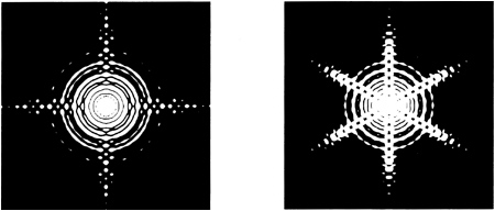
FIGURE 2.6 These synthetic images illustrate the task group’s calculations comparing ideal diffraction-limited point-spread functions (PSFs) for the ATD/NTOT (right) and HST (left) optical systems. Both are normalized to unit intensity, and both are identically saturated at the center to bring up the spider flares. The spatial scale is in units of λ/D (where D is the aperture). These images are intended to demonstrate the differences in the basic structure of the two PSFs due to the different means used to support each telescope’s secondary mirror. Since the two telescopes have different diameters and Strehl ratios, these figures would have to be rescaled in order to represent absolute energy content. At a wavelength of 0.6 micron, the Strehl ratio of the HST’s optical system is about twice that of the baseline ATD/NTOT, but the latter has 2.8 times the collecting area and its PSF is 1.7 times narrower at the same wavelength.
the truss, the inaccuracies of the other mirrors, and the jitter in the pointing of the ATD/NTOT. Table 2.2 also includes comparative data for the HST and also the Keck telescope (both with and without adaptive optics). It is clear that the enhanced design, which uses off-the-shelf technology, offers significant advances in astronomical performance over that of the HST, even taking into account the Advanced Camera that is currently under development for use with the HST. While not directly comparable, because of the effects of Earth’s atmosphere, the enhanced ATD/NTOT has a near-infrared performance rivaling that expected from the Keck telescope when it is eventually outfitted with adaptive optics.
FOCAL-PLANE SUITE
The baseline suite of focal-plane instruments is defined by the needs of nonastronomical users of the ATD/NTOT telescope. These instruments are summarized in Table 2.3. The beam from the FSM passes through a dichroic beam splitter that yields spatially separated infrared and optical beams. These in turn pass through neutral beam splitters and imaging optics (Figure 2.7).
The infrared detector of primary astronomical interest is the indium antimonide (InSb) array, assumed to be one of the new 1024 × 1024 arrays soon to be available from Hughes Santa Barbara Research Center. When operated at appropriately cold temperatures, this detector has state-of-the-art astronomical capabilities. The baseline design includes a pixel size of 0.05 arc sec. The task group assumes that the final scale of the imaging optics will be easily adjustable during the detailed design phase if it is decided to optimize the sampling of the PSF. It also assumes that the array will have the capability of subarray readout and/or many-amplifier fast readout that would allow, for example, multiple-sample reading of the array during a long integration.
The passive, visible, fine-tracking arrays are appropriate for some astronomical applications. But in the baseline design, they are line-transfer arrays with alternate rows masked for readout. Moreover, the amplifiers on the chips are not of the low-noise, low-speed design needed to minimize the readout noise. These arrays have
TABLE 2.2 Summary of Optical Performance for ATD/NTOT, Keck, and HST
|
Strehl Ratio |
Full Width at Half Maximum (mas) |
||||||
|
Wavelength |
Baseline ATD/NTOT |
Enhanced ATD/NTOT |
HST |
Keck with AO |
Keck without AO |
Baseline ATD/NTOT |
Enhanced ATD/NTOT |
|
0.5 |
0.3 |
0.6 |
~0.8 |
0 |
0 |
30 |
30 |
|
0.6 |
0.4 |
0.7 |
>0.8 |
<0.05 |
0 |
30 |
30 |
|
0.8 |
0.6 |
0.8 |
>0.8 |
0.14 |
0 |
40 |
40 |
|
1.0 |
0.7 |
0.8 |
>0.8 |
0.28 |
0 |
50 |
50 |
|
2.0 |
>0.8 |
>0.8 |
>0.8 |
0.73 |
<0.05 |
110 |
110 |
|
3.0 |
>0.8 |
>0.8 |
>0.8 |
>0.8 |
0.26 |
160 |
160 |
0.031-arc-sec pixels, but because of the alternate-row masking they do not adequately sample the PSF. The task group understands from the briefings from Lockheed that the substitution of frame-transfer arrays for the line-transfer arrays may be consistent with DOD’s technical goals. If so, this modification would go some of the way toward providing some, though not an optimum, optical astronomical capability.
NOTE: The values for the HST correspond to what would be delivered by the optical telescope assembly, corrective optics, and a well-sampled detector (such as the Faint Object Camera at visible wavelengths). The values for the Keck telescope assume that the telescope and its adaptive-optics (AO) system are behaving properly and that the atmosphere is in the 25th percentile (better than 0.35 arc sec). The image quality properties are dominated by the atmosphere for Keck without AO, and by the limited amount of correction that is applied using a single sodium laser artificial guide star. A Strehl ratio of 0.14 is comparable to that of the HST before the refurbishment mission.
The absence of a CCD of normal astronomical quality (i.e., one having a shutter, low dark current, slow readout, low-noise amplifiers, and so on) is a significant deficiency of the baseline focal plane. The baseline layout can easily accommodate an additional, large-format array that could be optimized for low noise. This possibility and other enhancements are discussed in Box 2.4, “Focal Plane Enhancements.”
ACQUISITION AND TRACKING
Image stability at high and low frequencies is derived, respectively, from the IPSRU and from observation of guide stars with the fine-tracking sensors. The error signals from the two sources are combined such that the IPSRU dominates for frequencies above 10 Hz and the fine trackers dominate for frequencies below 1 Hz. The fine trackers are read at 10 Hz and therefore contribute significantly to the tracking precision at frequencies up to about 3 Hz. At these rates, the fine trackers can follow a star with V magnitude near 19.
TABLE 2.3 Baseline Suite of Focal-Plane Instruments
|
Task |
Array Type |
Field of view (arc min) |
Pixels (no.) |
Pixel Size (arc sec) |
Aperture (cm) |
Wavelength (µm) |
|
Visible acquisition |
Si CCD |
175 × 175 |
512 × 512 |
121 |
7.5 |
0.4 - 0.8 |
|
Infrared acquisition |
PtSi |
235 × 175 |
640 × 480 |
23 |
7.5 |
1.0 - 5.0 |
|
Visible coarse tracking |
Si CCD |
3.5 × 3.5 |
512 × 512 |
0.4 |
400 |
0.4 - 0.8 |
|
Infrared coarse tracking |
PtSi |
4.6 × 3.4 |
640 × 480 |
0.4 |
400 |
2.7 |
|
Active visible, fine tracking |
Si CCD (with intensifier) |
0.5 × 0.5 |
512 × 512 |
0.06 |
400 |
0.53 |
|
Passive visible, fine track (×2) |
Si CCD (line transfer) |
1.1 × 1.1 |
2048 × 2048 |
0.03 |
400 |
0.4 - 0.8 |
|
Infrared imaging |
InSb |
0.9 × 0.9 |
1024 × 1024 |
0.05 |
400 |
0.9 - 5.5 |
|
Diameter of 50% Encircled Energy (mas) |
|||||||
|
HST |
KECK with AO |
KECK without AO |
Baseline ATD/NTOT |
Enhanced ATD/NTOT |
HST |
KECK with AO |
KECK without AO |
|
43 |
350 |
350 |
>160 |
60 |
53? |
400 |
400 |
|
50 |
340 |
340 |
>190 |
50 |
65? |
390 |
390 |
|
70 |
17 |
320 |
80 |
60 |
85? |
360 |
360 |
|
85 |
21 |
300 |
80 |
70 |
105? |
350 |
350 |
|
170 |
42 |
270 |
140 |
140 |
210? |
50 |
300 |
|
250 |
62 |
62 |
200 |
200 |
320? |
70 |
280 |
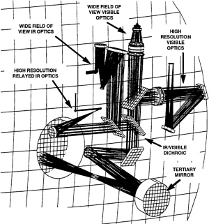
FIGURE 2.7 Schematic of a possible layout for the ATD/NTOT’s focal plane. The beam from the fast steering mirror is reflected by a folding mirror and then passes through a dichroic beam splitter to spatially separate infrared and optical beams. These in turn pass through neutral beam splitters and reimaging optics to bring them to focal points on various array detectors (Courtesy of Lockheed.)
|
Box 2.4 Focal Plane Enhancements Hardware modifications to the spacecraft can be very expensive, particularly if they are driven by many scientific requirements. Nevertheless, some particular hardware enhancements seem desirable in light of potential deficiencies in the ATD/NTOT’s baseline instrument suite. Optical Framing Camera The first and most important enhancement that should be considered is the addition of a suitable framing camera. This instrument should have the characteristics of an astronomical CCD camera. In other words, it should be capable of shuttered exposures, 100% sampling of the focal plane (no masked columns), and slow readout for minimal noise. A cheaper option would be to replace one or both of the line-transfer CCDs (i.e., ones in which every other column is masked for readout) in the fine-tracking detectors with frame-transfer CCDs. Other attributes to be considered include cooling for minimum dark current in long exposures and thermal control for photometric stability. The effective area of the telescope is given by the ratio of the number of photons arriving at the focal plane per unit time from a given source to the number of photons incident per unit time per unit area on the aperture from the same source. In other words, it is the area of an aperture that collects as many photons as the real system would collect if it were 100% efficient. Thus the effective area takes into account the losses due to obscuration of the aperture by the secondary mirror, losses due to reflection at all surfaces, and the quantum efficiency of the detectors. The full area of a 4-meter circular aperture is 12.6 m2; the task group estimates that the tracking of CCDs will have an effective area of somewhat less than 3 m2 and believes that with careful attention to losses, an effective area near 6 m2 is possible with a high-quality framing CCD. A goal for this camera might be a readout noise of 3 electrons rms with a dark current of fewer than 10 electrons per hour per pixel. A thinned, back-illuminated chip is desirable to minimize the effects of cosmic-ray hits on the detector. Exposures should be precisely controllable from roughly 1 second to at least 10 minutes. Ultraviolet sensitivity is not needed, and the detector and camera should probably be optimized for sensitivity at 0.7 to 0.8 microns. The pixel size should fully sample the point-spread function (PSF) at the shortest wavelength at which the telescope will work, say at 0.5 micron, implying a pixel size near 25 milliarc sec. The size of the array should be as large as practically possible at the time of building the camera, certainly 2048 × 2048, and larger if mosaics of several chips are feasible. While a 2048-chip is adequate for the technology demonstrations, the astronomical return from the mission is dramatically improved by increasing the size of the array as much as possible. The task group notes that there is ample space available for this camera in the focal plane as laid out in Lockheed’s preliminary designs. There are many groups in the country capable of designing and constructing such a camera. While it has made no careful estimates of the cost, the task group thinks that a suitable instrument would cost in the range of $3 million to $15 million. It notes that the far more sophisticated Hubble Advanced Camera for Exploration (HACE), recently selected by NASA, has a quoted price of $30 million. The trade-offs should be explored between building the camera as part of the DOD sensor suite (perhaps even by the teams that built the cameras for Clementine), building it at a university as less than a class-A instrument, and building it to normal NASA specifications at a center such as the Jet Propulsion Laboratory or through a competitive bid. The important point is that the camera should be large but otherwise simple and that the procurement must be highly streamlined and cost-effective. However such a camera is built, the astronomical community must be involved at an early stage to ensure that the camera meets astronomical needs. The justifications for adding an optical framing camera derive from both the technology demonstrations (see Chapter 4) and from subsequent astronomical operations (see Chapter 5). The alternate-column masking of the fine-tracking sensor in the DOD baseline focal plane prohibits the proper sampling of the PSF of images of point sources necessary to adequately characterize the performance of the telescope. Thus, adequate comparison of the images with the wavefront interferograms is impossible. Furthermore, the fast readout required for the fine-tracking sensors makes them unsuitable for the long exposures that are essential both for evaluating the tracking and guidance capability and for the astronomical observations. While the InSb array adequately samples the PSF at near-infrared wavelengths, the PSF at these wavelengths is significantly worse than that at shorter wavelengths because the diffraction limit is worse. The evaluation of the technology demands that images be properly sampled at the shortest possible wavelength, which in this case is near 0.5 micron. The camera thus provides the best end-to-end test of the integrated system, including all of the new technological components of the ATD/NTOT. The inclusion of this camera is the enhancement that would most dramatically improve the astronomical return from the mission. It would improve the quality of a Kuiper Disk search (see Chapter 5) by at least an order of magnitude. It is also the key factor that makes the search qualitatively different from one that could be done with the HST if the HST were devoted solely to that search for many months. The task group therefore views inclusion of the optical framing camera as the single most urgent addition of hardware to the focal plane. |
|
Cooled Infrared Array Provided that the necessary funds are available, other enhancements to the baseline instrument suite should also be considered. The baseline InSb array is likely to be similar to the ones widely used in astronomy. However, the baseline design does not include maximum cooling to minimize the array’s dark current, nor does it include special steps for passive cooling of the telescope structure and its optics. The InSb array will therefore be limited by local thermal emission, either of its own or from the telescope. Modifying the infrared design to optimize the cooling of the array and of the telescope structure is the second most important modification to the focal plane. The task group did not have sufficient details to evaluate this option critically but thinks it likely that a cooled infrared array would not be an expensive addition. Dedicated Focal Planes The imaging arrays in the baseline design have many optical surfaces between the detector and the telescope. This arrangement is particularly harmful in the infrared where the thermal emission from all these surfaces increases the background. It appears that it should be possible to pick off part of the telescope beam that is nearly on axis, namely the part that would strike the back of the fast steering mirror, and use it with suitable optics to feed a focal plane with a minimum of intermediate surfaces. The task group has done no studies of the optics required nor determined how best to deal with tracking in this configuration, although using an internal steering mirror driven by the feedback signals from the fine-tracking array seems a possibility. While such an addition is likely to be expensive, a study of the cost/performance trade-off seems justified before deciding arbitrarily whether such an enhancement is appropriate. |
The IPSRU has demonstrated a stability of 7.2 milliarc sec rms, integrated over frequencies from 0.1 to 100 Hz, with the spectrum of noise decreasing with increasing frequency. A briefing from IPSRU’s manufacturer, Charles Stark Draper Laboratories, revealed that this performance was limited by the quality of the gyros in the demonstration unit. It is thought that higher-quality gyros could be obtainable and the noise reduced to 1.9 milliarc sec rms.
The FSM can steer over a field of ±1.9 degrees, which translates to ±5.7 arc min on the sky after allowing for the 40:1 demagnification of the pupil (and the consequent 40:1 increase in the field divergence) and a factor-of-two gain in the motion due to reflection. This mobility is adequate to eliminate the anticipated F-SAT jitter of 1.2 arc min (3-sigma excursion).
OPERATIONS, ORBIT, COMMUNICATIONS, AND POWER REQUIREMENTS
The baseline mission assumes that the ATD/NTOT is launched into a circular parking orbit with a 200-km altitude using a Proton booster. As of early 1995 this launcher had a 19-year record of success (some 190 launches), averaging about 10 launches per year and with a success rate (last 50 moving average) of 96%. It is not clear at this time whether DOD’s mission would be carried out from a low circular orbit, such as the parking orbit, or from an elliptical orbit that carries the spacecraft to much higher altitudes. This choice has direct implications for the way in which astronomical demonstrations are conducted as well as for any longer-term astronomical research programs. However, either choice can be accommodated, since the baseline mission includes an eventual boost to a high-apogee, elliptical orbit.
The ATD/NTOT mission has a design lifetime of 1 year, and Lockheed ’s experience shows that such a mission, once past initial failures, has a high probability of lasting at least 5 years. The DOD mission is anticipated to take 6 to 12 months to complete. Since the demonstrations of astronomical capability must, at least in part, be carried out after the DOD mission, the task group has assumed that there will be an astronomical phase to the mission. For purposes of further discussion, 1 year is assumed for the national security mission and 5 years for the astronomical mission.
The standard Proton booster (the D-1-e model) has four stages, with the fourth stage normally being used to inject the payload into its final orbit. The fourth-stage shroud, however, is not large enough to accommodate a 4-meter telescope. Thus, the baseline ATD/NTOT mission assumes the use of the three-stage variant of the Proton (the D-1 model) and additional propulsion modules. These stages will boost the spacecraft into a 200-km parking orbit that, because of launch-azimuth restrictions at Baikonur Cosmodrome, is limited to an inclination of 51.6, 64.8, or 72.7 degrees.1 The baseline mission briefed to the task group would use the additional propulsion modules to boost the spacecraft at some time, either shortly after launch or after completing demonstrations of defense technology, from the parking orbit to a Molniya orbit (named after the class of Russian communications satellites that use this orbit). This type of orbit has an inclination of 63.4 degrees, is very eccentric, and has a nominal period of 12 hours. Perigee occurs at high southern latitudes at an altitude of about 400 km, while apogee is at a correspondingly high northern latitude at a nominal altitude of 22,000 km. Although some of the demonstrations of astronomical technology can readily be carried out from the low-altitude, circular, parking orbit, the Molniya orbit is the one in which most demonstrations of astronomical technology and essentially all astronomical observations for scientific purposes would be carried out. The use of alternative launch vehicles and possible orbital enhancements are discussed in Boxes 2.5 and 2.6, respectively.
In the baseline mission, the ATD/NTOT spacecraft carries some 500 kg of hydrazine for attitude control and maneuvering. It is expected that less than 10% of this fuel would be used in DOD’s technology demonstrations, leaving significant maneuvering capability for a long-duration mission. In fact, the fuel reserve is more than enough for months of astronomical technology demonstrations and 5 years of astronomical observations.
The baseline communications capability is 5 megabits per second averaged over each orbit, and on-board data storage is 8 gigabytes. Use of the worldwide Air Force Satellite Control Network for mission control and data readout is assumed. The transmitter-antenna combination assumed for the baseline mission has an 8-dB margin above the minimum, at the apogee of the Molniya orbit, for a 10−6 bit error rate. This communications capability is sufficient to reduce the bit error rate significantly. The task group assumes that the spacecraft will have a
|
Box 2.5 Alternative Launch Vehicles The selection of the launch system is critical to maintaining an overall affordable cost envelope. The basic mission mass to be put into low Earth orbit is of the order of 3900 kg, including the F-SAT bus but with no additional scientific instruments or weight contingency. In addition, the current design requires a shroud diameter slightly greater than 4 meters, which must couple physically and dynamically to the selected launch vehicle. In the past, only U.S. launch vehicles would have been considered, including the Shuttle, Titan IV, and Atlas II, all at a cost considerably in excess of $100 million. A broader list would include the European Ariane 4 and 5 (also very expensive) and the Chinese (PRC) Long March. With the end of both the Cold War and CO-COM trade restrictions with former Soviet republics, Russia’s large, reliable, and relatively inexpensive space boosters are becoming increasingly available for consideration. A preliminary analysis indicates that the Molniya-A, Zenit, and Proton boosters would be capable of lifting the F-SAT bus and the ADT/NTOT to low Earth orbit. The Zenit and Proton are of particular interest because each has a U.S. partner (Boeing and Lockheed-Martin, respectively), and the Proton, which will be used as the supply vehicle for the International Space Station Alpha, has a new shroud with 4.2-meter internal diameter. With the Proton’s low Earth orbit lift capacity of some 22,000 kg, one or more additional large satellites could be included to share the estimated $60 million cost. The Molniya-A is another newly available and highly successful (over 1000 launched to date) launcher that has an upper-stage integral with a 4.1-meter shroud and that can lift 7000 kg into low Earth orbit and more than 2700 kg directly into the desired Molniya orbit, for an estimated price of about $15 million. This summary indicates that numerous boosters are suitable for placing the ADT/NTOT into orbit and that Russian boosters are very attractive from the standpoint of price, availability, reliability, and existing shroud availability. Further, the availability of existing Russian upper stages and the ability of Russian launchers to lift excess weight could lead to further cost reductions in the basic telescope system itself, for an overall mission cost lower than that originally projected by Lockheed and Itek. The main issue not addressed so far is one of policy, that of DOD purchasing a Russian launch system. The benefits suggest strongly that this approach should be seriously considered. |
|
Box 2.6 Special Orbits The infrared performance of the ATD/NTOT is likely to be maximized if the telescope is operated at as low a temperature as possible. The largest obvious contributors to the heating of the telescope are sunshine (the same for all geocentric orbits) and earthshine (varying drastically with geocentric distance and direction). Studies of alternative orbits, from the point of view of both cooling and efficient operations, should be carried out during the final design phase. The orbits to be considered might include IRAS-like polar orbits orthogonal to the solar direction, IUE-like geosynchronous or even geostationary orbits, and SIRTF-like heliocentric orbits. The current communications capability might be inadequate for some of these (it would certainly be inadequate for the heliocentric orbit), and some orbits may be incompatible with DOD’s need for evaluating its technology. These considerations deserve further exploration. |
capability for lossless data compression, by at least a factor of two for essentially all data and by a factor of five for many types of data. It also assumes that some on-board processing will also be available that can, for example, take the median of several images to remove cosmic-ray hits (in cases for which that is desired) so that only median images need be transmitted to Earth. These assumptions provide a wide margin for the anticipated load of communications during the astronomical phases of the mission.
The power supplied by the F-SAT bus in the baseline mission is estimated at more than 3 kW at the end of a 6-year lifetime. Of this, approximately 1200 W would be used for spacecraft operations and communications, leaving some 2 kW for payload components. It is assumed that the payload provided for the DOD’s technology demonstrations will take only a small fraction of this capability. Thus at least 1 kW of power should be available at the end of the ATD/NTOT’s anticipated lifetime for any additions to the payload required by the astronomical tasks.
REFERENCE
1. Proton Launch Vehicle and Launch Services: User’s Guide, Lockheed-Khrunichev-Energia International, Inc., San Jose, Calif., 1993.


